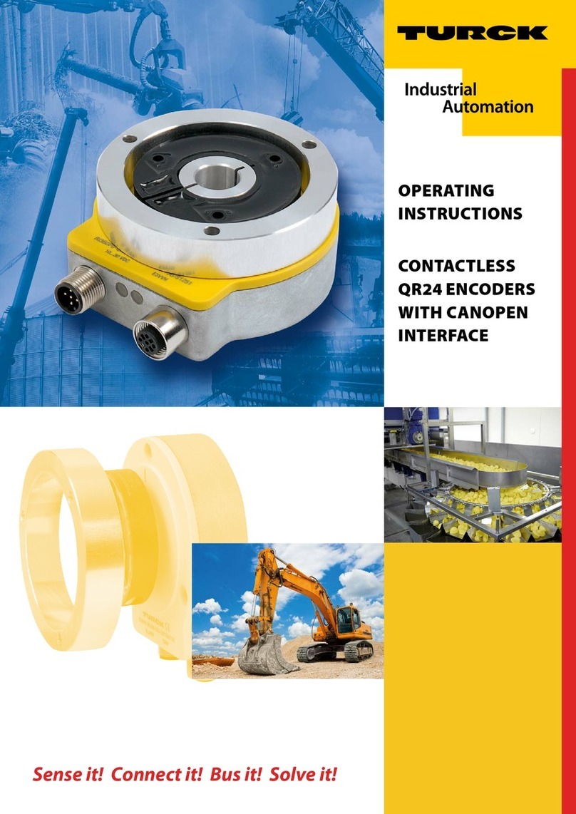
turck RI360P0 IOLX2 3GD Series User manual

Your Global Automation Partner
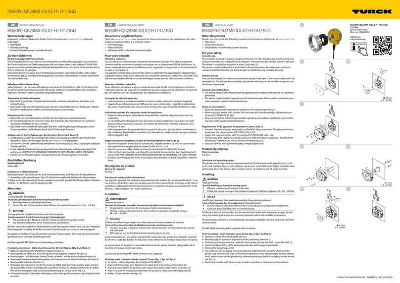
RI360P0-…-IOLX2-…/3GD
Encoders with
IO-Link Interface
Instructions for Use

Contents
Hans Turck GmbH & Co. KG | T +49 208 4952-0 | [email protected] | www.turck.com V01.00 | 2023/01 | 2
Contents
1 About these instructions ...................................................................................................................4
1.1 Target groups ...................................................................................................................4
1.2 Explanation of symbols used.........................................................................................4
1.3 Other documents.............................................................................................................4
1.4 Feedback about these instructions ..............................................................................4
2 Notes on the product .........................................................................................................................5
2.1 Product identification .....................................................................................................5
2.2 Scope of delivery..............................................................................................................5
2.3 Turck service .....................................................................................................................5
3 For your safety.....................................................................................................................................6
3.1 Intended use .....................................................................................................................6
3.2 Obvious misuse ................................................................................................................6
3.3 General safety notes........................................................................................................6
3.4 Notes on Ex protection ...................................................................................................6
3.5 Requirements for Ex approval for operation in zone 2 and 22 ...............................6
4 Product description ............................................................................................................................7
4.1 Device overview...............................................................................................................7
4.1.1 Indication elements.........................................................................................................................7
4.2 Properties and features ..................................................................................................8
4.3 Operating principle .........................................................................................................8
4.4 Functions and operating modes...................................................................................8
4.4.1 IO-Link mode......................................................................................................................................8
4.5 Encoders — components and accessories..................................................................9
4.5.1 Encoder — QR24/3GD sensor......................................................................................................9
4.5.2 Encoder — QR24 positioning element.....................................................................................9
4.5.3 Encoder — QR24 reducing bushings for PE1-QR24 positioning elements.............. 12
4.5.4 Encoders — protecting rings and mounting sets for QR24 device types ................ 16
4.5.5 Encoders — general accessories ............................................................................................. 18
5 Installing ............................................................................................................................................ 19
5.1 Front mounting — shaft diameters up to 20 mm .................................................. 20
5.2 Rear mounting — shaft diameters up to 20 mm .................................................... 22
5.3 Mounting on large rotatable machine part ............................................................. 24
6 Connection ........................................................................................................................................ 26
6.1 Wiring diagram.............................................................................................................. 26
7 Commissioning................................................................................................................................. 27
7.1 Setting IO-Link mode ................................................................................................... 27
8 Operation........................................................................................................................................... 28
8.1 Maximum speed............................................................................................................ 28
8.2 LED display..................................................................................................................... 28
9 Setting................................................................................................................................................ 29
9.1 Setting via IO-Link ........................................................................................................ 29
9.1.1 IO-Link parameters ....................................................................................................................... 29
9.1.2 IO-Link process data..................................................................................................................... 29

Contents
Hans Turck GmbH & Co. KG | T +49 208 4952-0 | [email protected] | www.turck.com V01.00 | 2023/01 | 3
10 Troubleshooting............................................................................................................................... 30
11 Maintenance ..................................................................................................................................... 31
12 Decommissioning ............................................................................................................................ 32
13 Disposal.............................................................................................................................................. 32
14 Technical data................................................................................................................................... 33
15 Appendix ........................................................................................................................................... 34
15.1 Approvals and markings ............................................................................................. 34
16 Turck subsidiaries — contact information.................................................................................. 35

About these instructions
Feedback about these instructions
Hans Turck GmbH & Co. KG | T +49 208 4952-0 | [email protected] | www.turck.com V01.00 | 2023/01 | 4
1 About these instructions
These instructions for use describe the structure, functions and the use of the product and will
help you to operate the product as intended. Read these instructions carefully before using the
product. This is to avoid possible damage to persons, property or the device. Retain the instruc-
tions for future use during the service life of the product. If the product is passed on, pass on
these instructions as well.
1.1 Target groups
These instructions are aimed at qualified personnel with knowledge of explosion protection
(e.g. EN 60079-14 etc.) and must be carefully read by anyone mounting, commissioning,
operating, maintaining, dismantling or disposing of the device.
1.2 Explanation of symbols used
The following symbols are used in these instructions:
DANGER
DANGER indicates a dangerous situation with high risk of death or severe injury if
not avoided.
WARNING
WARNING indicates a dangerous situation with medium risk of death or severe
injury if not avoided.
CAUTION
CAUTION indicates a dangerous situation of medium risk which may result in minor
or moderate injury if not avoided.
NOTICE
NOTICE indicates a situation which may lead to property damage if not avoided.
NOTE
NOTE indicates tips, recommendations and useful information on specific actions
and facts. The notes simplify your work and help you to avoid additional work.
uCALL TO ACTION
This symbol denotes actions that the user must carry out.
aRESULTS OF ACTION
This symbol denotes relevant results of actions.
1.3 Other documents
Besides this document, the following material can be found on the Internet at www.turck.com:
nData sheet
nQuick Start Guide
nIO-Link parameters manual
nCommissioning manual IO-Link devices
1.4 Feedback about these instructions
We make every effort to ensure that these instructions are as informative and as clear as
possible. If you have any suggestions for improving the design or if some information is missing
in the document, please send your suggestions to [email protected].

Notes on the product
Turck service
Hans Turck GmbH & Co. KG | T +49 208 4952-0 | [email protected] | www.turck.com V01.00 | 2023/01 | 5
2 Notes on the product
2.1 Product identification
These instructions apply to the following encoder:
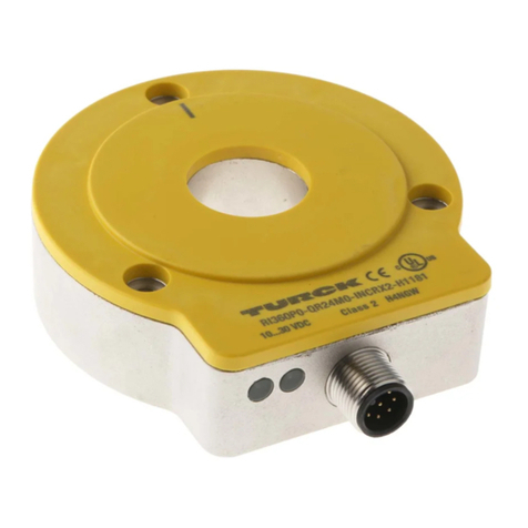
nRI360P0-QR24M0-IOLX2-H1141/3GD
2.2 Scope of delivery
The scope of delivery includes:
nEncoder – Sensor
nMounting aid MT-QR24
nQuick Start Guide
2.3 Turck service
Turck supports you with your projects, from initial analysis to the commissioning of your applic-
ation. The Turck product database under www.turck.com contains software tools for program-
ming, configuration or commissioning, data sheets and CAD files in numerous export formats.
The contact details of Turck subsidiaries worldwide can be found on p. [}35].

For your safety
Requirements for Ex approval for operation in zone 2 and 22
Hans Turck GmbH & Co. KG | T +49 208 4952-0 | [email protected] | www.turck.com V01.00 | 2023/01 | 6
3 For your safety
The product is designed according to state-of-the-art technology. However, residual risks still
exist. Observe the following warnings and safety notices to prevent damage to persons and
property. Turck accepts no liability for damage caused by failure to observe these warning and
safety notices.
3.1 Intended use
The rotary encoders with an IO-Link interface are used for measuring speeds and angle move-
ments. To do this the devices detect mechanical rotary movements and convert them into a
digital IO-Link telegram. The devices can be operated and parameterized via an IO-Link inter-
face with IO-Link masters compliant with specification 1.1. Process and diagnostics data can be
exchanged with the higher controller level during operation via IO-Link.
The device is suitable for operation in zone 2 and zone 22.
The devices may only be used as described in these instructions. Any other use is not in accord-
ance with the intended use. Turck accepts no liability for any resulting damage.
3.2 Obvious misuse
nThe devices are not safety components and must not be used for personal or property
protection.
nAny use that exceeds the maximum permissible mechanical speed (see technical data) is
deemed to be not in accordance with the intended purpose.
3.3 General safety notes
nThe device may only be assembled, installed, operated, parameterized and maintained by
professionally-trained personnel.
nIf safe operation can no longer be guaranteed: Shut down the device and lock out to prevent
accidental startups.
nThe device may only be used in accordance with applicable national and international
regulations, standards and laws.
nThe device meets the EMC requirements for industrial areas. When used in residential areas,
take measures to avoid radio interference.
3.4 Notes on Ex protection
nWhen operating the device in a hazardous area, the user must have a working knowledge of
explosion protection (IEC/EN 60079-14, etc.).
nObserve national and international regulations for explosion protection.
nOnly use the device within the permitted operating and ambient conditions (see certifica-
tion data and Ex approval requirements for use in Ex area ).
3.5 Requirements for Ex approval for operation in zone 2 and 22
nConnect the device using a separately certified M12 plug connection. The plug connection
must meet the requirements of IEC/EN 61076-2-101.
nSecure the male connector with the supplied SC-PM12/3GD safety clip.
nPermanently affix a label close to the connector with the following warning: NICHT UNTER
SPANNUNG TRENNEN/DO NOT SEPARATE WHEN ENERGIZED
nOnly use devices with a protecting ring or impact protection.

Product description
Device overview
Hans Turck GmbH & Co. KG | T +49 208 4952-0 | [email protected] | www.turck.com V01.00 | 2023/01 | 7
4 Product description
The inductive encoders of the RI360P…-QR24 series measure speeds and angle movements up
to 360º. The sensor and positioning element of encoders are fully potted and designed as two
separate fully sealed units with protection type IP69K that work together without contact. The
encoder sensor can be connected to shafts with a diameter of up to 20mm using the reducing
bushings and mounting elements which are available as an option. A mounting element for
mounting on large rotatable machine parts is also included in the range.
The QR24 encoders with an IO-Link interface can be connected via a 3-wire connection cable
with a 4-pin standard male connector. The devices can be operated and set via IO-Link.
4.1 Device overview
ø 4.3
ø 65
ø 74
24
15.3
81
10
42.3
LED
ø 78
M12 x 1
ø 3.2
ø 42
ø 20
120°
24
81
10
42.3
LED
ø 78 ø 22 ø 4.3ø 65
M12 x 1
fig.1: QR24 encoder with sensor, P1 position-
ing element (optional) and protecting ring (op-
tional)
fig.2: Encoder — sensor (front)
ø 42 M4 x 0.5 x 7.5
ø 3.2
ø 20
ø 52
ø 42 10
fig.3: Encoder — sensor (rear) fig.4: Encoder — positioning element P1
4.1.1 Indication elements
The devices are provided with a green Power supply LED and a yellow Status LED.

Product description
Functions and operating modes
Hans Turck GmbH & Co. KG | T +49 208 4952-0 | [email protected] | www.turck.com V01.00 | 2023/01 | 8
4.2 Properties and features
nOperation and setting via IO-Link
nSingle-turn, 16-bit resolution
nProcess value in 32-bit IO-Link telegram
n3 error bits
n13 multiturn bits
n16 single-turn bits
nConnection via 4-pin M12 × 1 male connector
4.3 Operating principle
The QR24 encoders have contactless operation based on the inductive resonant circuit measur-
ing principle. This measuring principle makes it possible to design a fully encapsulated sensor
housing without seals, which is separated from the positioning element. Magnetic fields cannot
disturb the measuring process since the positioning element is not based on a magnet but on
an inductive coil system, through which the sensor and the positioning element (resonator) can
form an oscillation circuit. The inductive measuring principle of the QR24 encoder is absolute.
4.4 Functions and operating modes
The devices can be operated in IO-Link mode. The devices must be connected to an IO-Link
master for operation in IO-Link mode. Different device functions can be configured via the
IO-Link interface.
4.4.1 IO-Link mode
IO-Link mode provides bidirectional IO-Link communication between an IO-Link master and
the sensors. For this the devices are integrated in the controller level via an IO-Link master. The
switching signals are processed via the process data of the IO-Link interface. Besides the switch-
ing information, diagnostics and identification messages can be queried via IO-Link. The follow-
ing device parameters can be adapted to the particular application via IO-Link:
nDevice access protection
nRotation direction
nZero setting
nMultiturn reset
nReset settings

Product description
Encoders — components and accessories
Hans Turck GmbH & Co. KG | T +49 208 4952-0 | [email protected] | www.turck.com V01.00 | 2023/01 | 9
4.5 Encoders — components and accessories
4.5.1 Encoder — QR24/3GD sensor
Dimension drawing Type Description
24
81
10
42.3
LED
ø 78 ø 22 ø 4.3ø 65
M12 x 1
RI360P…-
QR24…/3GD
Encoder – sensor, QR24 design, die
cast zinc housing (without positioning
element)
4.5.2 Encoder — QR24 positioning element
The positioning elements are connected with the moving part of the machine (shaft) but move
freely (without any mechanical connection to the sensor) over the active face of the sensor.
Different reducing bushings are available to adapt the positioning element to the particular
shaft diameter.
Dimension drawing Type Description
ø 3.2
ø 52
ø 42 10
PE1-QR24 Positioning element without
reducing bushing
ø 3.2
ø 20
ø 52
ø 42 10
P1-RI-QR24 Positioning element with
aluminum reducing bushing
to connect to Ø 20 mm shafts

Product description
Encoders — components and accessories
Hans Turck GmbH & Co. KG | T +49 208 4952-0 | [email protected] | www.turck.com V01.00 | 2023/01 | 10
Dimension drawing Type Description
ø 3.2
ø 52
ø 42 10
ø 14
P2-RI-QR24 Positioning element with
aluminum reducing bushing
to connect to Ø 14 mm shafts
ø 3.2
ø 52
ø 42 10
ø 12
P3-RI-QR24 Positioning element with
aluminum reducing bushing
to connect to Ø 12 mm shafts
ø 3.2
ø 52
ø 42 10
ø 10
P4-RI-QR24 Positioning element with
aluminum reducing bushing
to connect to Ø 10 mm shafts
ø 3.2
ø 52
ø 42 10
ø 6
P5-RI-QR24 Positioning element with
aluminum reducing bushing
to connect to Ø 6 mm shafts

Product description
Encoders — components and accessories
Hans Turck GmbH & Co. KG | T +49 208 4952-0 | [email protected] | www.turck.com V01.00 | 2023/01 | 11
Dimension drawing Type Description
ø 3.2
ø 52
ø 42 10
ø 3/8“
P6-RI-QR24 Positioning element with
aluminum reducing bushing
to connect to Ø 3/8" shafts
ø 3.2
ø 52
ø 42 10
ø 1/4“
P7-RI-QR24 Positioning element with
aluminum reducing bushing
to connect to Ø 1/4" shafts
ø 3.2
ø 52
ø 42 10
P8-RI-QR24 Positioning element with
aluminum blanking plug,
e.g. for mounting on large
rotatable machine parts
ø 3.2
ø 52
ø 42 10
ø 1/2“
P9-RI-QR24 Positioning element with
aluminum reducing bushing
to connect to Ø 1/2" shafts

Product description
Encoders — components and accessories
Hans Turck GmbH & Co. KG | T +49 208 4952-0 | [email protected] | www.turck.com V01.00 | 2023/01 | 12
Dimension drawing Type Description
ø 3.2
ø 52
ø 42 10
ø 5/8“
P10-RI-QR24 Positioning element with
aluminum reducing bushing
to connect to Ø 5/8" shafts
ø 3.2
ø 3/4“
ø 52
ø 42 10
P11-RI-QR24 Positioning element with
aluminum reducing bushing
to connect to Ø 3/4" shafts
4.5.3 Encoder — QR24 reducing bushings for PE1-QR24 positioning elements
Dimension drawing Type Description
ø 24
ø 28
2
9.9
ø 20
RA1-QR24 Aluminum reducing bushing
to connect to Ø 20 mm shafts
ø 24
ø 28
2
9.9
ø 14
RA2-QR24 Aluminum reducing bushing
to connect to Ø 14 mm shafts

Product description
Encoders — components and accessories
Hans Turck GmbH & Co. KG | T +49 208 4952-0 | [email protected] | www.turck.com V01.00 | 2023/01 | 13
Dimension drawing Type Description
ø 24
ø 28
2
9.9
ø 12
RA3-QR24 Aluminum reducing bushing
to connect to Ø 12 mm shafts
ø 24
ø 28
2
9.9
ø 10
RA4-QR24 Aluminum reducing bushing
to connect to Ø 10 mm shafts
ø 24
ø 28
2
9.9
ø 6
RA5-QR24 Aluminum reducing bushing
to connect to Ø 6 mm shafts
ø 24
ø 28
2
9.9
ø 3/8“
RA6-QR24 Aluminum reducing bushing
to connect to Ø 3/8" shafts

Product description
Encoders — components and accessories
Hans Turck GmbH & Co. KG | T +49 208 4952-0 | [email protected] | www.turck.com V01.00 | 2023/01 | 14
Dimension drawing Type Description
ø 24
ø 28
2
9.9
ø 1/4“
RA7-QR24 Aluminum reducing bushing
to connect to Ø 1/4" shafts
ø 24
ø 28
2
9.9
RA8-QR24 Aluminum reducing bushing
(e.g. for mounting the posi-
tioning element on large
rotatable machine parts)
ø 24
ø 28
2
9.9
ø 1/2“
RA9-QR24 Aluminum reducing bushing
to connect to Ø 1/2" shafts
ø 24
ø 28
2
9.9
ø 5/8“
RA10-QR24 Aluminum reducing bushing
to connect to Ø 5/8" shafts

Product description
Encoders — components and accessories
Hans Turck GmbH & Co. KG | T +49 208 4952-0 | [email protected] | www.turck.com V01.00 | 2023/01 | 15
Dimension drawing Type Description
ø 24
ø 28
2
9.9
ø 3/4“
RA11-QR24 Aluminum reducing bushing
to connect to Ø 3/4" shafts
ø 24
ø 28
2
9.9
ø 18
RA12-QR24 Aluminum reducing bushing
to connect to Ø 18 mm shafts

Product description
Encoders — components and accessories
Hans Turck GmbH & Co. KG | T +49 208 4952-0 | [email protected] | www.turck.com V01.00 | 2023/01 | 16
4.5.4 Encoders — protecting rings and mounting sets for QR24 device types
Different mounting sets are required for different mounting types (see section “Mounting”).
Each mounting set contains an aluminum protecting ring and an aluminum shielding plate.
The shield plates enable the quality of the signal between the positioning element and the
sensor to be increased depending on mounting type and application. The protecting rings are
also available individually in aluminum and plastic.
Dimension drawing Type Description
ø 74
ø 4.5
ø 65
ø 57
120°
14.3
M1-QR24 Aluminum protecting ring
ø 74
ø 4.5
ø 65
120°
2
M2-QR24 Mounting set (for front mount-
ing of the sensor on shafts up
to Ø20mm):
M1-QR24 aluminum protect-
ing ring + SP1-QR24 aluminum
shield plate: Ø 74 mm
ø 74
ø 4.5
ø 65
ø 22
120°
2
M3-QR24 Mounting set (for front mount-
ing of the sensor on shafts up
to Ø20mm):
M1-QR24 aluminum protect-
ing ring + SP2-QR24 aluminum
shield plate: Ø 74 mm,
with Ø 22 mm hole for shaft
feedthrough

Product description
Encoders — components and accessories
Hans Turck GmbH & Co. KG | T +49 208 4952-0 | [email protected] | www.turck.com V01.00 | 2023/01 | 17
Dimension drawing Type Description
ø 52
ø 3.2
ø 42
120°
2
M4-QR24 Mounting set (for mounting
the positioning element on
large rotatable machine parts):
M1-QR24 aluminum protect-
ing ring + SP3-QR24 aluminum
shield plate: Ø 52 mm
ø 74
ø 4.5
ø 65
120°
2
SP1-QR24 Aluminum shield plate:
Ø 74 mm for rear mounting of
the sensor on shafts up to
Ø20mm
ø 74
ø 4.5
ø 65
ø 22
120°
2
SP2-QR24 Aluminum shield plate:
Ø 74 mm, with Ø 22 mm hole
for shaft feedthrough for front
mounting of the sensor on
shafts up to Ø 20 mm
ø 52
ø 3.2
ø 42
120°
2
SP3-QR24 Aluminum shield plate:
Ø 52 mm for mounting the
positioning element on large
rotatable machine parts

Product description
Encoders — components and accessories
Hans Turck GmbH & Co. KG | T +49 208 4952-0 | [email protected] | www.turck.com V01.00 | 2023/01 | 18
4.5.5 Encoders — general accessories
Dimension drawing Type Description
1.5
MT-QR24 Mounting aid for optimum
alignment of the positioning
element (supplied)
42
11.5
ø 15
M12 x 1
L
M12 x 1ø 15
49.5
18.2
RKC4.4T-2-RSC4.4T/TXL Connection cable, M12 female
connector, straight 4-pin, M12
male connector, straight 4-pin,
cable length: 2 m, jacket
material: PUR, black; cULus
approval; other cable lengths
and qualities available,
see www.turck.com
42
11.5
ø 15
M12 x 1
L
50
5
RKC4.4T-2/TXL Connection cable, M12 female
connector, straight 4-pin, cable
length: 2 m, jacket material:
PVC, black; cULus approval;
other cable lengths and
qualities available,
see www.turck.com

Installing
Hans Turck GmbH & Co. KG | T +49 208 4952-0 | [email protected] | www.turck.com V01.00 | 2023/01 | 19
5 Installing
The optionally available adapter sleeves and mounting elements enable the front or rear of the
encoder sensors to be fitted to the shafts with a diameter of up to 20 mm. With large rotatable
machine parts, the positioning element is screwed directly onto the machine part and not
fitted on the shaft.
WARNING
Improper fixing
Possible fatal injury from fast moving parts!
Observe mounting instructions in all cases.
Check the secure seating of the positioning element, tightening torque:
M = 0.6…0.8 Nm.
NOTICE
Insufficient clearance from metal surrounding the positioning element
Loss of functionality due to weakening of resonant circuit
Ensure sufficient clearance between the surrounding area and positioning
element.
Carry out a function test prior to commissioning.
NOTE
The positioning element must be located in the middle of the measuring range of
the sensor before the power supply is applied.

Installing
Front mounting — shaft diameters up to 20 mm
Hans Turck GmbH & Co. KG | T +49 208 4952-0 | [email protected] | www.turck.com V01.00 | 2023/01 | 20
5.1 Front mounting — shaft diameters up to 20 mm
1. Optional: Use shield plate.
2. Position the mounting aid for optimum alignment of the positioning element.
1.
2.
fig.5: Inserting the shield plate
3. Push the positioning element – with the front (active face) to the shaft – onto the shaft.
4. Fasten clamp fitting of the positioning element with hexagon spanner.
0.6…0.8 Nm
2.5 mm
3.
4.
fig.6: Fastening the positioning element
Table of contents
Other turck Media Converter manuals

turck
turck REM Series User manual

turck
turck QR24 User manual

turck
turck RI QR20 Series User manual

turck
turck Ri-QR24 User manual

turck
turck Ri-QR24 User manual

turck
turck RES Series User manual

turck
turck FOC1 Series User manual

turck
turck Ri-QR24 User manual

turck
turck CANopen DW60 User manual

turck
turck RM-97 User manual