Power Fist 8732315 User manual

V1.0 8732315
Please read and understand all instructions before use. Retain this manual for
future reference.

This page is intentionally left blank.

SPECIFICATIONS
Capacity 2,000 lb
Maximum Length 51 in.
Maximum Height 80 in.
Lift Range 5 to 80 in.
Reach 51 in.
Operation Mode Manual
Swivel Angle 360º
Material Steel
Colour/Finish Powder Coat, Black
Mounting Size 10 x 10 in.
Winch Capacity 2,000 lb
Winch Cable 30 ft
INTRODUCTION
This easy-to-use crane is perfect for lifting and loading generators, pressure
washers, drum barrels and other heavy cargo onto trucks and trailers. It
features a 360° pivoting base.
SAFETY
WARNING! Read and understand all instructions before using this tool.
The operator must follow basic precautions to reduce the risk of
personal injury and/or damage to the equipment.
HAZARD DEFINITIONS
Please familiarize yourself with the hazard notices found in this manual. A
notice is an alert that there is a possibility of property damage, injury or death
if certain instructions are not followed.
DANGER! This notice indicates an immediate and specic hazard that will result in
severe personal injury or death if the proper precautions are not taken.
WARNING! This notice indicates a specic hazard or unsafe practice that could result in
a serious injury if the proper precautions are not taken.
CAUTION! This notice indicates a potentially hazardous situation that may result in
minor or moderate injury if proper practices are not taken.
NOTICE! This notice indicates that a specic hazard or unsafe practice will result in
equipment or property damage, but not personal injury.
V1.0 TRUCK MOUNT CRANE 8732315
Page 3 www.princessauto.com / 1-800-665-8685

WORK AREA
1. Operate in a safe work environment. Keep your work area clean, well-lit
and free of distractions. Place lights so you are not working in a shadow.
2. Keep anyone not wearing the appropriate safety equipment away from
the work area.
3. Store unused tools properly in a dry, safe and secure location to prevent
rust, damage or misuse.
PERSONAL SAFETY
WARNING! Wear personal protective equipment approved by the
Canadian Standards Association (CSA) or American National Standards
Institute (ANSI).
PERSONAL PROTECTIVE EQUIPMENT
1. Always wear impact safety goggles that provide front and side protection
for the eyes. Eye protection equipment should comply with CSA Z94.3-07
or ANSI Z87.1 standards based on the type of work performed.
2. Wear steel toe footwear or steel toe caps to prevent a foot injury from
falling objects.
PERSONAL PRECAUTIONS
Control the tool, personal movement and the work environment to avoid
personal injury or damage to tool.
1. Do not operate any tool when tired or under the inuence of drugs,
alcohol or medications.
2. Avoid wearing clothes or jewelry that can become entangled with the
moving parts of a tool. Keep long hair covered or bound.
SPECIFIC SAFETY
WARNING! DO NOT let comfort or familiarity with product (gained from
repeated use) replace strict adherence to the tool safety rules. If you use
this tool unsafely or incorrectly, you can suer serious personal injury.
1. Use the correct tool for the job. This tool was designed for a specic
function. Do not modify or alter this tool or use it for an unintended
purpose.
2. Failure to follow these instructions may result in loss of load, damage
to the crane, and/or crane failure resulting in personal injury or property
damage.
8732315 TRUCK MOUNT CRANE V1.0
www.princessauto.com / 1-800-665-8685 Page 4

3. Do not allow untrained persons to operate the crane.
4. Use the crane for lifting only. Do not work under a load that is supported
only by the crane.
5. Stabilize the load. Ensure that the load remains stable at all times. Lift
deadweight only.
6. Know the weight of the load being lifted. DO NOT overload the crane
beyond the rated capacity of each specied boom position. Overloading
can cause damage or failure of the crane.
7. The vehicle with the crane should be on a level surface capable of
sustaining the weight of the vehicle and load. Use of the crane on other
than level surfaces can result in crane instability and possible loss of load
or tipping of the vehicle.
8. Make sure there is enough clearance around the crane and the load for
movement.
9. Never attempt to use the crane unless it is properly lled with hydraulic
uid. Do not use brake uid or any other improper uid and avoid mixing
dierent types of oil when adding hydraulic oil.
10. Inspect the tool before each use. DO NOT use if bent, broken, cracked,
leaking, otherwise damaged, if any suspect parts are noticed or it has
been subjected to a shock load.
11. Check to ensure that all applicable bolts and nuts are rmly tightened.
12. Store the crane with the boom fully lowered, winch cable retracted,
hydraulic ram valve closed and position the boom over the vehicle's wheel
well when storing or driving.
JACK PRECAUTIONS
1. Do not use a handle extension for the jack handle.
2. Make sure the load is stable, so it does not shift when lifting or lowering.
3. Ensure that there are no obstructions under the load and that the area is
clear before lowering the device.
4. Lower the load in a slow and controlled manner to prevent shock loading.
Shock loading may cause to fail and lead to property damage and/or
severe personal injuries.
LIFTING PRECAUTIONS
1. Do not exceed the maximum capacity to prevent equipment failure or
damage.
V1.0 TRUCK MOUNT CRANE 8732315
Page 5 www.princessauto.com / 1-800-665-8685

2. Inspect the device before each use. Do not use if it is bent, cracked,
damaged or has been subjected to a sudden or unexpected (shock) load.
3. Ensure that all applicable pins, bolts and nuts are rmly tightened before
using.
4. Use only with accessories rated to handle the forces exerted by the device
during operation. Other accessories may break and forcefully launch
pieces.
5. Do not place your hands between moving components.
WINCH SAFETY
1. All users must understand the operation of all controls and learn how to
stop the winch quickly in case of emergency.
2. Keep hands clear of the winch and wire rope when spooling the line in or
out. Hold the wire rope by the strap. Fingers caught in the hook may be
pulled into the mechanism and crushed or pinched.
3. Never fully extend the wire rope while under load. Keep four complete
turns of the wire rope around the winch drum.
4. Do not exceed the winch load capacity.
5. Do not use the winch if damaged or it was subjected to a dynamic
shock load. Have the winch inspected and repaired by a qualied service
technician.
6. Always use proper couplings when connecting the winch cable hook,
sling, eyebolt or other accessory to the load. Never connect the hook back
to the wire rope. This causes wire rope damage. Always use a sling or
chain of suitable strength.
7. Do not use inappropriate attachments to extend the length of the winch
wire rope.
8. After moving an item with the winch, secure the item. Do not rely on the
winch to hold it for an extended period.
9. Make sure the rope spools onto the drum in touching wraps. A rope that
cannot move without impediment can create a dangerous situation that
can injury you or a bystander or damage the load and/or the winch.
10. Never lift people or hoist loads over people.
11. Never come in-between the winch and the load when operating
12. Never operate the winch if the wire rope shows any signs of weakening, is
knotted or kinked.
8732315 TRUCK MOUNT CRANE V1.0
www.princessauto.com / 1-800-665-8685 Page 6

HYDRAULIC PRECAUTIONS
DANGER! Seek immediate medical attention if hydraulic uid under
pressure penetrates your skin. See Injection Injury precautions for
instructions before using a pressurized hydraulic system.
1. Do not touch or handle components while under pressure. Hydraulic uid
escaping under pressure has sucient force to penetrate your clothing
and skin. A pinpoint hole may inject hydraulic uid into your body. Seek
immediate medical attention if this occurs (see Injection Injury).
2. Never exceed the hydraulic system’s load capacity (see Specications).
3. Do not adjust the hydraulic system’s relief setting. The settings are preset
by the factory.
4. Hydraulic oil under pressure is hot and can cause a burn injury if touched,
sprayed or spilled. Allow the hydraulic system to cool before conducting
maintenance.
5. Hydraulic components require regular inspection. Release all pressure
from the system before you inspect it. Replace damaged hydraulic parts
with identical manufacturer's components.
6. Do not attempt makeshift repairs to a hydraulic system. Such repairs can
fail suddenly and create a hazardous condition.
7. Hydraulic uid has a combustible ash point of 200°F (93°F). Do not
expose the uid to an ignition source.
8. Change your clothing immediately if sprayed with hydraulic uid. Store
clothing or rags contaminated with hydraulic uid in an approved metal
safety can with a spring-closing lid and venting designed to contain a re.
9. Only use hydraulic uid in the pump. Do not substitute or mix brake uid,
or any other uid, with the hydraulic uid. This can result in a pump
failure and injure the user or bystander. It may also damage the pump.
INJECTION INJURY
DANGER! Seek immediate, professional medical treatment if uid
penetrates your skin. It may feel like a pricking or sting. Do not wait
for the appearance of symptoms. A toxic reaction can occur from the
exposure. Delay in treatment can lead to amputation or death.
Inform the medical sta that you have a uid penetration injury as soon as you
arrive at the medical facility. The severity of the symptoms will depend on the
type of uid injected. Bring the Safety Data Sheet for the uid with you to the
medical facility if possible.
V1.0 TRUCK MOUNT CRANE 8732315
Page 7 www.princessauto.com / 1-800-665-8685

INJECTION PRECAUTIONS
Fluid can penetrate the skin at 100 PSI pressure. Fluid escaping under pressure
from the tool has sucient force to penetrate your clothing and skin. Follow
the precautions below to avoid an injection injury.
1. Always check for leaks wearing a face shield, safety goggles, rubberized
gloves and protective clothes.
2. Release all pressure from the system before you inspect it.
3. Do not use your hands to detect a leak. Use a large piece of wood,
cardboard or paper and watch for discolouration.
4. Replace damaged parts with identical manufacturer's components to
ensure it is rated to handle the pressure.
UNPACKING
WARNING! Do not operate the tool if any part is missing. Replace
the missing part before operating. Failure to do so could result in a
malfunction and personal injury.
Remove the parts and accessories from the packaging and inspect for damage.
CONTENTS
Make sure that all items in the contents are included.
• Base
• Post
• Boom
• Boom Extension
• Long Ram Hydraulic Jack
• Jack Handle
• Chain and Hook
• Winch and Cable with Hook
• Winch Handle
• Pulley
• Assorted Hardware (Bolts, Washers,
Lock Washers and Nuts)
8732315 TRUCK MOUNT CRANE V1.0
www.princessauto.com / 1-800-665-8685 Page 8
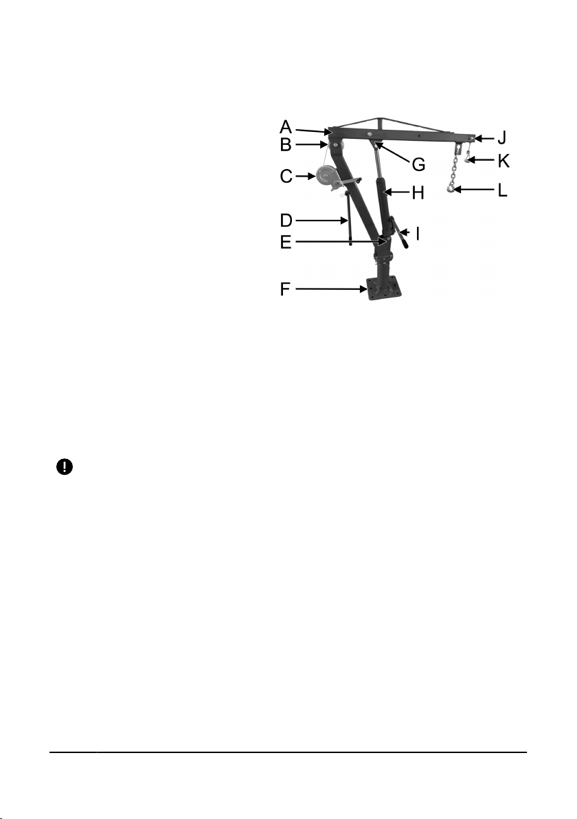
IDENTIFICATION KEY
A. Boom
B. Pulley
C. Winch
D. Crane Handle
E. Jack Attachment Point
F. Base
G. Jack Attachment Point
H. Long Ram Hydraulic Jack
I. Jack Handle
J. Boom Extension
K. Wire Rope and Hook
L. Chain and Hook
ASSEMBLY & INSTALLATION
ASSEMBLING THE CRANE
Some components are heavy and dicult to maneuver while installing.
Have another person available to help you during installation.
1. Place the base in the truck bed and check for proper clearance when the
crane is in use and when stored. A right rear corner mount is typical.
a. A wood truck oor will require the installation of a 3/8 in. thick steel
plate approximately six to eight inches larger than the base plate on
top of the wooden deck. If the oor is heavy metal and ribbed, no
metal plate is required under the crane base plate, but lling in the
ribbed oor to level it may be required. The base may now be placed
in position and used to locate the mounting holes through the truck
bed and back plate.
b. Dierent truck models may require additional bracing as the load
will be directed over the largest area possible. If additional bracing
is desired, install a brace which crosses both sides of the truck and
may be used with an outrigger, stabilizer or jack leg holder to keep
the truck stable during lifting operations.
FIGURE 1.
V1.0 TRUCK MOUNT CRANE 8732315
Page 9 www.princessauto.com / 1-800-665-8685

2. Check the mounting location below the truck bed
to avoid wiring, gas tanks, muers, etc. Adjust the
base position if needed to avoid puncturing the
understructure when drilling.
3. Use the base as a template and mark the holes that
you will use to mount the base to the truck bed.
Move the base aside.
4. Drill holes into the truck bed. Make sure the drill and
drill bit are suitable for drilling through the metal.
Use cutting oil if necessary.
5. Reposition the base over the holes. Secure in place
with bolts, washers and nuts (sold separately). Only
use hardware that exceeds the weight capacity of
the crane.
6. Insert the bearing (#43) into the base. Screw the base
handle (#34) into the base until the bearing is held in
place (Fig. 2).
7. Slide the post over the base and align the holes in
each (Fig. 3). Insert a bolt (#27) through each hole.
Slide a washer (#8) and lock washer (#7) over the
bolts and secure with a nut (#6).
8. Insert the boom into the post’s top bracket (Fig. 4).
Position the large pulley inside the boom so the
bushings align with the bolt holes. Insert a bolt (#42)
through the bolt holes. Secure with a washer (#24),
lock washer (#23) and nut (#22).
• Ensure the connection point for the hydraulic
jack is on the bottom and near the post when
connecting the boom.
9. Follow the instructions for
Installing The Jack
in the next section.
10. Slide the boom extension into the
boom. Until the hole in the boom
aligns with the hole at the 2,000 lb
mark.Insert a bolt (#21) through the
bolt holes. Secure with a washer (#24),
lock washer (#23) and nut (#22).
FIGURE 2.
FIGURE 3.
FIGURE 4.
8732315 TRUCK MOUNT CRANE V1.0
www.princessauto.com / 1-800-665-8685 Page 10
FIGURE 5.

11. Follow the instructions for
Installing
The Chain And Hook.
INSTALLING THE JACK
WARNING! The hardware (bolts, pin, washers, lock washers and
nuts) used to attach the jack to the equipment must be capable
of withstanding the load without deforming or breaking to prevent
equipment failure and/or personal injuries.
The hardware is included.
1. Align the ram’s bolt hole with the bolt
hole on the equipment's attachment
point. The attachment point location will
vary depending on the equipment and
application.
2. Insert a bolt (#21) through the mounting
points and the ram's bolt hole.
• Secure the bolt with a washer (#24),
lock washer (#23) and nut (#22).
3. Place the the clevis mount over the clevis
attachment point on the equipment and
align the bolt holes.
4. Insert a bolt (#27) through the clevis mount and attachment point. Secure
with a washer (#24), lock washer (#23) and nut (#22).
INSTALLING THE WINCH
Remove the wire rope from the winch before installation.
1. Prepare the hardware by sliding a lock washer (#39), then a washer (#38)
over the each bolt (#37). Set aside within easy reach.
2. Position the winch's base on the post. The winch's handle will be on the
right-hand side. Align the base's bolt holes with the post's screw holes.
Hold the winch in place.
3. Insert one of the prepared bolts through the base's bolt holes and screw
the bolt into post. Repeat with the other three prepared bolts. Tighten
each bolt until the lock washer begins to compress.
BEFORE FIRST USE
The steel rope must be broken-in before using to lift a heavy load. The break-in
process will stretch the cable, ensure the individual wires are seated and the
FIGURE 6.
V1.0 TRUCK MOUNT CRANE 8732315
Page 11 www.princessauto.com / 1-800-665-8685

wire compacted. Run the winch with a light load several times, before normal
use.
Also use a weight when spooling the wire rope onto the winch. This will
provide the correct tension when spooling.
INSTALLING A WIRE ROPE
1. Remove the bolt that connects the boom and boom
extension and set aside.
2. Push the boom extension into the boom.
3. Lift the boom so it is at a slight upward angle. The
angle will hold the boom extension in place.
4. Insert the end of the wire rope through the hole in the
bottom of the boom extension. Pull several feet of wire
rope through the hole.
5. Feed the wire rope down the boom extension and
boom until it comes out the other end.
6. Place the wire rope onto the pulley in the boom and
boom extension.
7. Continue pulling wire rope out of the boom until you
are sure it won't be pulled back by its own weight.
8. Mount and wrap the wire rope onto the winch.
MOUNTING A NEW WIRE ROPE
1. Pull the end of the wire rope over the top of
the drum.
2. Insert the wire rope end through a side hole
in the drum from the inside. Pull about one to
two feet of wire rope out.
3. Guide the wire rope into the next hole and pull
the excess through. Leave enough line to form
a large loop.
4. Guide the wire rope through the next hole from the inside and pull the
excess through.
5. Insert the end of the wire ripe under the large loop. The end must extend
past the loop, but stay within the edge of the drum to avoid impeding
rotation.
FIGURE 7.
FIGURE 8.
FIGURE 9.
8732315 TRUCK MOUNT CRANE V1.0
www.princessauto.com / 1-800-665-8685 Page 12

6. Hold the end of the wire rope in place. With your other hand, remove the
wire rope's slack by pulling it back through the holes, until the loop traps
the rope end.
7. Reel the new wire rope onto the drum by turning the handle, being careful
not to allow kinking.
8. Test the winch for proper operation.
MOUNTING A NEW WIRE ROPE
1. Route the end of the new wire rope under the bushing and through the
hole to the outside of the drum.
2. Insert the wire rope under the cable clamp.
3. Tighten the cable nut securely.
4. Reel the new wire rope onto the drum by turning the handle, being careful
not to allow kinking.
5. Test the winch for proper operation.
INSTALLING THE CHAIN AND HOOK
Make sure the chain, hook and hardware are rated to exceed the crane's weight
capacity.
1. Choose a short length of chain to avoid problems with clearing obstacles
when raising the load.
2. Attach a suitable shackle to the top chain link.
3. Align the shackle openings with the connection point on the boom
extension. Insert a bolt through the shackle and the connection point.
Secure the bolt with a nut or tighten if the shackle is threaded.
4. Attach another shackle and a hook to the bottom chain link, if the chain
does not have one already.
OPERATIONS
WARNING! No one other than the people involved in moving the load
should be in or on the vehicle. Anyone near the vehicle may be seriously
injured or killed if the load falls or the vehicle tips over under a heavy
load. Ensure each person has an unobstructed escape route away from
the work area.
V1.0 TRUCK MOUNT CRANE 8732315
Page 13 www.princessauto.com / 1-800-665-8685

WARNING! Dynamic shock loads are created by quick opening and
closing of the release valve when lowering the load. The resulting
overload may cause the hydraulic system to failure, which could result
in severe personal injury and/or property damage.
Inspect the crane at the beginning of the day before lifting. Any defects or
problems should be corrected before use.
The crane has two options for lifting and moving cargo: by hydraulic jack or by
manual winch. You can use them together or separately to lift a load.
1. Determine the load’s weight.
2. Adjust the boom extension position to 1,000 lb or 2,000 lb, based on the
load’s weight. Reinsert the bolt and secure with the washers and nut used
during assembly. The weight capacity of the boom arm is written next to
each bolt hole on the boom.
3. Position the vehicle so the crane can reach the load. Do this after
adjusting the boom extension arm in the previous step.
4. Keep the vehicle as level as possible during operation and always lift the
load straight up.
5. Loosen the base handle and rotate the crane until it is over the load.
6. To prevent the boom from swinging freely, always tighten the base handle
before lifting a load, after the load is positioned or when storing the crane
after use.
7. Always use outriggers (jack legs) from the truck to the ground. Be sure
these are rm and adequately positioned.
RAISING A LOAD
1. Close the release valve. Insert the slotted end of the handle over the valve
and twist to the right.
2. Insert the handle (#16) into the bottle jack's receiver.
3. Pump the handle until the load reaches the desired height.
LOWERING A LOAD
WARNING! Dynamic shock loads are created by quick opening and
closing of the release valve when lowering the load. The resulting
overload may cause the hydraulic system to failure, which could result
in severe personal injury and/or property damage.
WARNING! Before lowering the load, ensure that there are no
obstructions underneath and that all people are standing clear.
8732315 TRUCK MOUNT CRANE V1.0
www.princessauto.com / 1-800-665-8685 Page 14

1. Insert the slotted handle end over the release valve.
2. Open the release valve by slowly rotating the handle counterclockwise.
The load will descend as pressure is released from the jack’s system.
Control the speed by rotating the handle.
a. Rotate the handle counterclockwise to increase the speed.
b. Rotate the handle clockwise to decrease the speed.
3. Open the release valve fully once the ram has fully retracted.
4. Position supports, like jack stands, if the load will remain above ground
for an extended period. Consult the support device's manual for proper
placement.
5. Once the supports are carrying the load, open the valve to allow the ram
to retract fully.
6. When the work is done, raise the load enough with the jack to carefully
remove the supports.
HAND WINCH OPERATION
WARNING! Do not release the handle when the ratchet mechanism is
disengaged and there is a load on the line. The load will drop and can
cause a serious impact injury. The crank handle will also spin and can
cause a minor impact injury. Maintain a rm grip while unwinding until
the load is settled and there is slack in the wire rope.
The ratchet lever has 2 positions. The upper position is for winding the wire
rope onto the drum with the ratchet in gear. The lower position disengages the
ratchet pawl allowing the drum to freewheel in either direction.
WINDING/UNWINDING (NO LOAD)
1. Rotate the handle slightly to release pressure on the pawl.
2. Push the ratchet lever down until it clicks to disengage the ratchet
mechanism.
3. The drum can move freely in both directions.
4. Grasp the hook and pull the wire rope until the hook can be attached to
the load.
• Be careful as the crank handle will rotate freely and can cause an
impact injury if it strikes you.
5. Rewind any excessive wire rope by turning the crank handle. Make sure
the rope winds evenly onto the drum.
V1.0 TRUCK MOUNT CRANE 8732315
Page 15 www.princessauto.com / 1-800-665-8685

WINDING UNDER LOAD
1. Move the ratchet lever into the upper position to engage the pawl.
2. Turn the crank handle to wind the wire rope evenly onto the drum. The
pawl will click as it catches the drum's cog.
3. Continue turning the handle until the load is high enough to clear any
obstacles.
UNWINDING UNDER LOAD (LOWERING, UNLOADING)
1. Hold the crank rmly, then push gently to relieve tension on the ratchet
lever.
2. Push the ratchet lever down until it clicks to disengage the ratchet
mechanism.
3. Turn the crank handle to unwind the wire rope until the load has settled
and there is slack in the line.
4. You may need to stop the unloading task at some point. Hold the load in
place and re-engage the ratchet system. Then turn the crank handle to
raise the load until you hear the pawl click. Gradually ease pressure on the
handle until you are sure the pawl is locked in place.
5. The wire rope should be fully retracted again after use.
OPERATING THE CRANE
1. Before lifting, set the boom to the lowest practical position that will allow
your load to safely clear any objects in the swing path.
2. Attach a hook to the lift point on the load.
3. Follow the instructions for
Raising A Load
with the winch and jack.
4. Begin pumping the handle to raise the boom with the jack. Stop when
hook is in position, but not bearing the load's weight.
5. Check that the hook is in the best position to raise the load without it
shifting.
6. Ensure all bystanders are out of the way in case the load slips or shifts.
7. Once the load is near the boom, attach the other hook for additional
safety.
8. Continue raising the boom until the load is high enough to clear any
obstacles. Remove the jack handle and set aside.
9. Loosen the base handle and move the load slowly to the desired spot with
the crane handle.
8732315 TRUCK MOUNT CRANE V1.0
www.princessauto.com / 1-800-665-8685 Page 16

10. Tighten the base handle once the load is in position for lowering.
11. Depending on the location, you may choose to lower the load by either
lowering the boom or reversing the winch.
12. Insert the jack handle end over the relief valve.
13. Open the release valve by slowly rotating the handle counterclockwise.
This will open the pressure valve and the boom arm will lower. Never
open or close the valve abruptly, as it may damage the jack and endanger
personnel in the work area. Control the speed by rotating the handle.
14. Lower the load the rest of the way with the winch, if needed.
15. Once the load is safely in the vehicle or on the ground, release enough
pressure to remove the hook.
16. Store the crane once all lifting operations are complete. No part of the
crane should stick out of the vehicle and the boom should be fully
lowered.
a. Slide the boom extension fully into the boom and secure with the
bolt.
b. Swing the crane into position for travel.
c. Tighten the base handle to secure the crane in place.
d. Lower the boom fully.
e. Return the jack handle to the storage bracket on the main post
f. Wind the slack wire rope onto the winch drum and engage the
ratchet lever.
CARE & MAINTENANCE
1. Maintain the tool with care. A tool in good condition is ecient, easier to
control and will have fewer problems.
2. Inspect the tool components periodically. Repair or replace damaged or
worn components. Only use identical replacement parts when servicing.
3. Keep the tool handles or gripping surfaces clean and dry.
4. Maintain the tool’s labels and name plates. These carry important
information. If unreadable or missing, contact Princess Auto Ltd. for
replacements.
5. Have a qualied technician inspect the jack:
V1.0 TRUCK MOUNT CRANE 8732315
Page 17 www.princessauto.com / 1-800-665-8685

a. Once a year.
b. After receiving a shock load. Take the jack out of service until the
technician certies that it is safe to use.
WARNING! Only qualied service personnel should repair the tool. An
improperly repaired tool may present a hazard to the user and/or others.
HYDRAULIC RAM MAINTENANCE
Monthly maintenance is recommended for the hydraulic ram. Any restrictions
due to dirt, rust, etc. can cause the either slow movement or extremely rapid
jerks, damaging the internal components. The following steps are designed to
keep the pump maintained and operational.
1. Lubricate the cylinder and the pumping mechanism with light oil.
2. Visually inspect for cracked welds, bent, loose, missing parts or hydraulic
oil leaks.
3. Inspect the hydraulic ram immediately if it was subjected to an abnormal
load or shock load.
4. Remove any hydraulic jack from service that is damaged, worn down or
operates abnormally, until repaired by an authorized service technician.
5. Check and maintain the ram oil level.
6. Always store the hydraulic ram in the fully retracted position. This will
help protect critical areas from corrosion.
7. Do not use brake or transmission uids or regular motor oil as they can
damage the seals. Always purchase and use products labeled Hydraulic
Oil.
REFILL THE HYDRAULIC JACK
The pump may become less ecient when the hydraulic oil level is too low or
contaminated by metal particulate through normal wear-and-tear.
1. Retract the ram and remove the oil ller plug.
2. Check and maintain the ram oil level.
• Check the oil level with the oil dip stick. Use a long plastic cable tie
as a substitute if the unit does not have a dipstick.
3. Fill the cylinder with a high quality hydraulic jack oil, up to the oil plug
opening.
a. Place a funnel into the oil ll neck. The funnel opening should be
wide enough to prevent the oil from collecting in the funnel’s cone.
8732315 TRUCK MOUNT CRANE V1.0
www.princessauto.com / 1-800-665-8685 Page 18

b. Pour oil into the funnel. Allow the oil to settle for one minute and
recheck the level. Repeat until the desired level is reached.
4. Follow the steps in Bleeding the Hydraulic System.
5. Insert the oil ller plug and hand tighten.
6. Wipe up any spilled oil. Dispose of oil soaked rags in a proper hazardous
waste container.
REPLACE THE HYDRAULIC OIL
Replace the hydraulic oil annually.
The oil can be removed by using a uid extractor tool.
FLUID EXTRACTOR TOOL
1. Retract the ram and remove the oil ller plug.
2. Follow the instructions for your uid extractor tool to remove the old
hydraulic oil.
3. Follow the instructions for Rell the Hydraulic Jack.
MANUAL OIL REPLACEMENT
1. Relieve pressure from the system by opening the release valve, then
loosening the oil ller plug.
2. Remove the jack from the crane.
3. Remove the oil ll plug.
4. Lay the jack on its side and drain the oil into a suitable container. Dispose
of used hydraulic oil in accordance with local by-laws.
5. Stand the jack on its base and wipe o any excess oil.
6. Reinstall the hydraulic jack onto the crane.
7. Follow the instructions for Rell the Hydraulic Jack.
BLEEDING THE HYDRAULIC SYSTEM
Bleed excess air from the hydraulic system as follows:
1. Open the release valve by turning it counterclockwise.
2. Remove the oil ller screw and ll the hydraulic jack with hydraulic uid.
3. Wait 5 minutes for trapped air to rise to the surface.
4. Pump the handle for several strokes to eliminate any air in the system.
5. Check the oil ller hole and if necessary, top o with more hydraulic oil.
V1.0 TRUCK MOUNT CRANE 8732315
Page 19 www.princessauto.com / 1-800-665-8685

6. Restore the oil ller screw. Close the release valve by turning clockwise.
7. Test the ram several times for proper operation before putting it into use.
Do not use the ram if it still does not appear to be working properly. Have
a qualied service technician service or repair the hydraulic system.
FLUSHING THE VALVE
Contaminants may block the release valve, causing issues when attempting to
lower a load. Clear the valve with the following steps.
1. Lower the ram and securely close the release valve.
2. Manually lift the ram several inches.
3. Open the release valve and force the ram down as quickly as possible.
LUBRICATION
Clean and lubricate all moving parts.
Lubricate the grease tting with a grease gun once a month or when the boom
becomes dicult to swivel on the post.
HYDRAULIC FLUID DISPOSAL
Do not drain hydraulic oil into the sewer system or dispose in an uncontrolled
location. Hydraulic uid may take more than a year to breakdown in the
environment and the ingredients may still be toxic. Contact your local
municipality for proper disposal instructions or locations.
DISPOSAL
Recycle a tool damaged beyond repair at the appropriate facility.
Contact your local municipality for a list of disposal facilities or by-laws for
electronic devices, batteries, oil or other toxic liquids.
DO NOT pollute the environment by allowing uncontrolled discharge of
waste oil.
TROUBLESHOOTING
Visit a Princess Auto Ltd. location for a solution if the tool does not function
properly or parts are missing. If unable to do so, have a qualied technician
service the tool.
8732315 TRUCK MOUNT CRANE V1.0
www.princessauto.com / 1-800-665-8685 Page 20
Table of contents
Languages:
Other Power Fist Construction Equipment manuals

Power Fist
Power Fist 8901092 User manual

Power Fist
Power Fist 660 lb User manual

Power Fist
Power Fist 8622946 User manual

Power Fist
Power Fist 8536708 User manual

Power Fist
Power Fist 8712937 User manual

Power Fist
Power Fist 8668014 User manual

Power Fist
Power Fist 8625949 User manual

Power Fist
Power Fist 8536625 User manual

Power Fist
Power Fist 8924094 User manual
Popular Construction Equipment manuals by other brands


allen
allen AT-16 Operations & parts manual

Atlas Copco
Atlas Copco CA300 instruction manual

HYVA
HYVA HC801 WARNING, OPERATING AND MAINTENANCE MANUAL

allen
allen WB1224 Assembly & parts manual

Parkside
Parkside PFMR 1400 A1 Original operating instructions

Hog Technologies
Hog Technologies HT1000SR Operation manual


