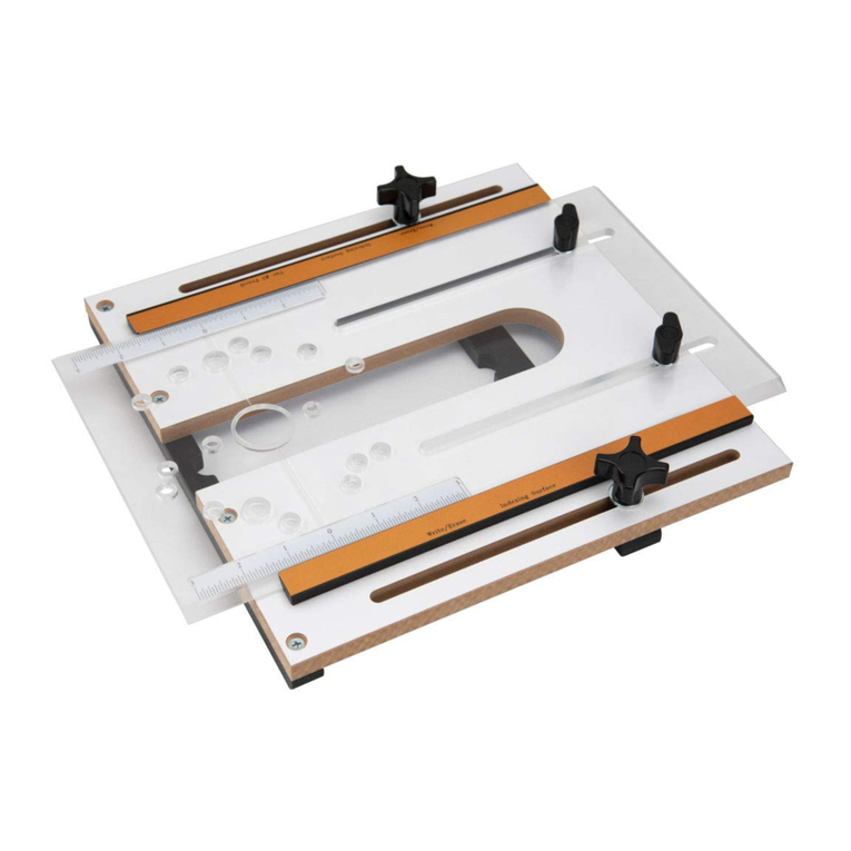
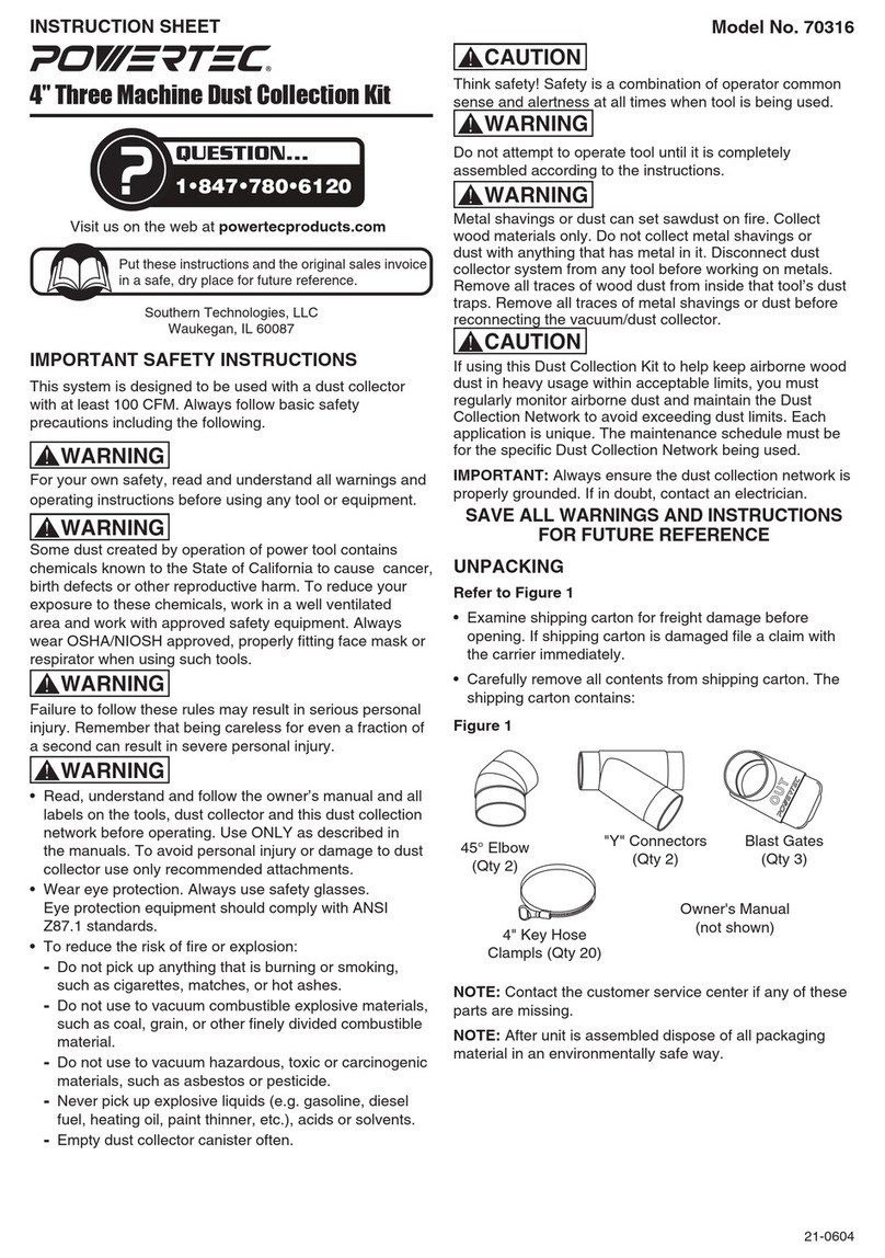
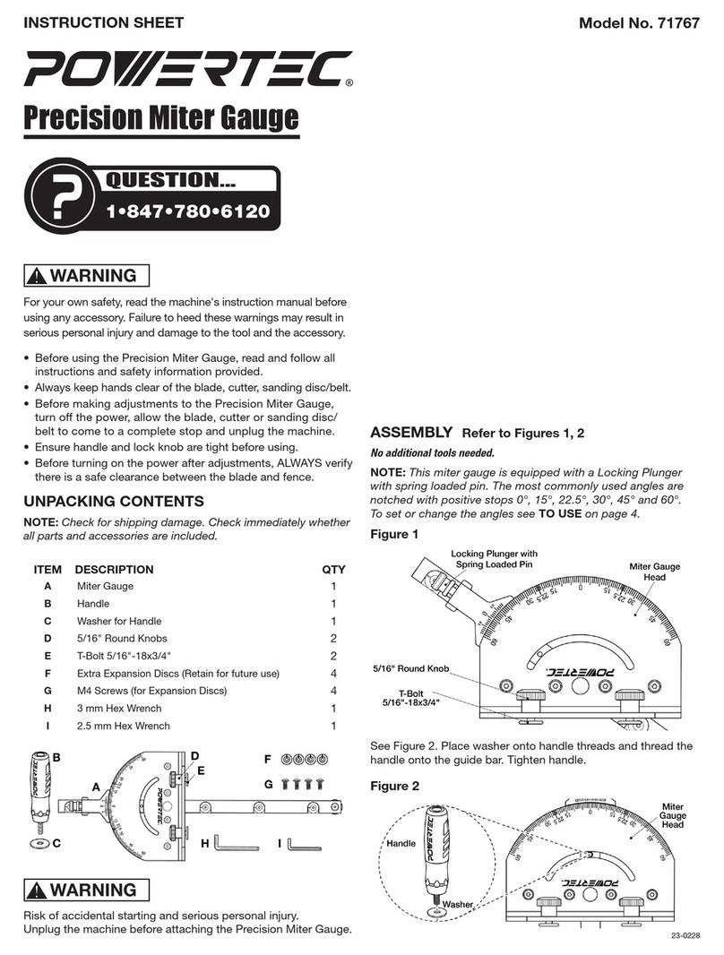
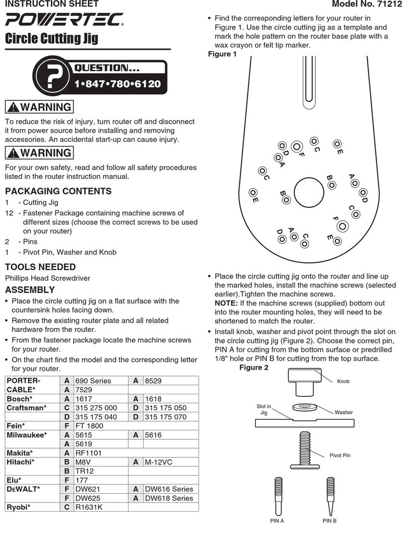
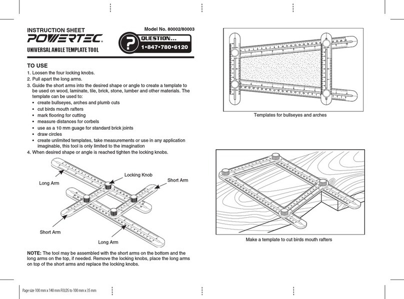
Power Tec 71395 User manual

Owner’s Manual
Model No. 71395
Taper/Straight Jig
You will need this manual for safety instructions, operating procedures, and warranty.
Put it and the original sales invoice in a safe, dry place for future reference.
Visit us on the web at powertecproducts.com
QUESTION...
1•847•780•6120
20-0903

PRODUCT
SPECIFICATIONS
TABLE OF CONTENTS
SAFETY RULES 1
ASSEMBLY 3
MAINTENANCE 6
General Maintenance
WARRANTY 7
SECTION PAGE
Assembly
Set Up
Base (MDF).............................32" x 7-7/8" x 1/2"
MDF adjustable fence ..................32" x 2-1/2" x 1-1/32"
Miter bar – aluminum .......................36" x 3/4"x 3/8"
OPERATION 5
Use

SAFETY RULES 1
1
SAFETY RULES
WARNING
For your own safety, read all of the rules and precautions before
operating tool.
WARNING
Always follow proper operating procedures as defined in this
manual even if you are familiar with use of this jig or any tool
used with this jig. Remember that being careless for even a
fraction of a second can result in severe personal injury.
Before using another tool with this product, always read,
understand and follow the instructions and safety warnings in
the owner’s manual for that tool. If you do not have the owner’s
manual, obtain one from the tool’s manufacturer before using it
with this product.
You must be familiar with the use of any tool or excessory used
with this jig. The supplier cannot be held responsible for any
accident, injury or damage incurred while using this jig with
any tool.
It is the responsibility of the purchaser of this product to ensure
that any person using this product reads and complies with all
instructions and safety precautions outlined in this manual and
the operating manual of the tool being used prior to use.
WARNING
Some dust created by operation of power tool contains
chemicals known to the State of California to cause cancer, birth
defects or other reproductive harm. To reduce your exposure
to these chemicals, work in a well ventilated area and work
with approved safety equipment. Always wear OSHA/NIOSH
approved, properly fitting face mask or respirator when using
such tools.
CAUTION
Do not modify or use this jig for any application other than that
for which it was designed.
FOLLOW ALL STANDARD SHOP SAFETY
PRECAUTIONS, INCLUDING:
• Keep children and visitors at a safe distance from work area.
• Keep work area clean. Cluttered work areas invite accidents.
Work area should be properly lit.
• Do not use power tools in dangerous environments. Do not
use power tools in damp or wet locations. Do not expose
power tools to rain.
• TURN OFF AND UNPLUG all power tools BEFORE making
any adjustments or changing excessories.
• Be alert and think clearly. Never operate power tools
when tired, intoxicated or when taking medications that
cause drowsiness.
• Wear proper apparel. Do not wear loose clothing, gloves,
neckties, rings, bracelets or other jewelry which may get
caught in moving parts of the tool.
• Wear protective hair covering to contain long hair.
• Wear safety shoes with non-slip soles.
• Wear safety glasses complying with United States ANSI
Z87.1. Everyday glasses have only impact resistant lenses.
They are NOT safety glasses.
• Wear face mask or dust mask if operation is dusty.
• A guard or any other part that is damaged should be properly
repaired or replaced. Do not perform makeshift repairs.
• Use safety equipment such as featherboards, push sticks and
push blocks, etc., when appropriate.
• Maintain proper footing at all times and do not overreach.
• Do not force woodworking tools.
CAUTION
Think safety! Safety is a combination of operator common sense
and alertness at all times when tool is being used.
WARNING
Do not use the jig until it is completely assembled and you
have read and understood this entire operating manual and the
operating manual of the tool being used with this jig.
SAVE ALL WARNINGS AND INSTRUCTIONS
FOR FUTURE REFERENCE

SPECIFIC SAFETY WARNINGS
2
DANGER
• To avoid serious injury, keep hands out of the path of
the spinning blade. Maintain awareness of the blade at
all times.
• Always turn off and unplug the saw when making
any adjustments
WARNING
• The jig is intended for use on table saws with a
standard 3/8"D x 3/4"W miter slot.
• During setup, the jig may need to be cut to fit your specific
saw. Read the instructions carefully to complete this
essential setup step.
• The hold-down clamps MUST be positioned so they will
NOT come into contact with saw blade.
• You MUST tighten all knobs and the hold down to secure
the workpiece after making any adjustments and before
making any cuts.
• Keep the saw blade as low as possible to make the cut, as
defined by your table saw’s instruction manual.
• Before making the actual cut, become familiar with the
cutting process by practicing the motion of the cut with the
blade lowered and the power turned off.
• Make sure there is sufficient out-feed support when cutting
long pieces.
• Do NOT attempt to cut pieces that are too narrow to be
secured to the jig with the hold-down clamps.
• The jig handle must be installed when making all taper and
straight cuts.
• The miter bar MUST be installed on the jig when making
taper cuts.
• When making taper cuts, position the miter bar in the miter
slot on the right side of the blade. See instructions for Miter
Bar Fine Adjustments.
• DO NOT use the table saw fence when making taper cuts.
• The adjustable stop on the jig fence MUST be used
during taper and straigth cuts. Make sure it is adjusted
so it DOES NOT come in contact with the blade and is
tightened securely.
• Remove the miter bar and use the jig with the table saw
fence when making straight cuts. ALWAYS reassemble the
miter bar before making taper cuts with the jig.

3
ASSEMBLY
ASSEMBLY 3
UNPACKING
Refer to Figure 1
Check for shipping damage. Check immediately whether all
parts and excessories are included.
ITEM DESCRIPTION QTY
ABase (MDF) 1
BAdjustable Fence with T-Track and Stop Plate 1
CAluminum Miter Bar 1
DTapered Knob (4" long) 1
EHold Down Clamps (5-1/2" long) 2
FFive Star knobs 4
GT-Bolts, 5/16"-18 x 2-1/2" 4
HTape Measure with Self-Adhesive Back 2
IAbrasive Grip Strips, 1-1/2" x 7" 3
JFlat Head Screw, 5/16"-18 x 1" 1
KScrew, 1/4"-20 x 3/4" 3
LWashers, 5/16" 5
MNylon Adjustment Screws, #10-32 9
NSmall Screwdriver 1
Figure 1
H
K
M
B
N
C
G
F
L J
EID
A
WARNING
Do not use the jig until it is completely assembled and you
have read and understood this entire operating manual and the
operating manual of the tool being used with this jig.
ASSEMBLY
Miter Bar and Tapered Knob
Refer to Figure 2–6
The miter bar is used when making taper cuts only. The miter
bar MUST be removed when straight line ripping.
NOTE: When making taper cuts, the jig is used in the miter slot
to the right of the blade for taper cutting. On some saws the
initial cut will remove a narrow piece of the jig's base to create
zero-clearance support.
1. Assemble the nine slotted nylon adjustment screws into the
miter bar. Do not tighten, adjustment will be made later.
2. Use the three 1/4"-20 x 3/4" screws to assemble the miter
bar to the bottom of the base. The miter bar is longer than
the base, position the extended portion away from the
operator. NOTE: There are two sets of mounting holes for
the miter bar, use the set of holes that will result in the least
amount of stock being removed during the initial cut. See
Figure 2.
Figure 2
Screw 1/4"-20 x 3/4"
Miter Bar
Bottom of
Base
Nylon Adjustment Screws (9)
Extended End
of Miter Bar
3. From the underneath the base, insert the 5/16"-18 x 1" flat
head screw through the hole near the rear edge of the base.
Place a washer onto the screw and thread on the tapered
knob. Tighten the tapered knob.
Tapered Knob
Washers 5/16"
Figure 3
Flat Head Screw, 5/16"-18 x 1"
4. Make sure the table saw’s blade is parallel to the table’s
miter slot and 90˚ to the table. If it isn’t, follow the saw
manufacturer’s guidelines to make necessary adjustments
so it is parallel to the miter slots and square to the table.
5. Lower the blade below the table surface.

4
ASSEMBLY
Miter Bar Adjustment
WARNING
The miter bar MUST be able to slide freely forward and
backward without side-to-side play. NEVER attempt to force the
crosscut sled if it fails to slide freely.
1. Place the miter bar on the jig into the right miter slot of the
table saw and slide it to evaluate the fit. The jig should slide
easily but not shift side to side. If adjustments are needed:
-Remove the jig and turn it over. Use the supplied
small screwdriver to adjust the nylon adjustable
screws (See Figure 3). Make necessary adjustments
until the jig slides easily but does not shift side
to side.
Trim the Base to Fit the Table Saw
Being Used
NOTE: Some saws will not require the jig/base to be trimmed.
When the jig is placed in the miter slot any excess material will
need to be trimmed from the base.
NOTE: The jig is used in the miter slot to the right of the blade
for taper cutting.
2. Place the base on the saw's table with the miter bar in
the miter slot and clear of the blade. See the Miter Bar
Adjustment instructions, if needed.
3. Pull the jig back until it is clear of the cutting area, turn on
the saw, raise the blade and then push the jig through the
blade to make the cut to trim the jig's base to create a zero-
clearance edge.
Figure 4
Miter Bar in Slot
Base
Excess
Material
Apply Tape Measures and Abrasive
Grip Strips
1. Remove the adhesive backing from the tape measures
and press into place at each end of the base. Align the "0"
on the tape measures with the zero-clearance edge. Use
scissors to cut the excess tape.
2. Remove the adhesive backing from the abrasive grip strips
and press onto the base, align the strips to the zero-
clearance edge as shown. DO NOT cover up the miter
bar screws.
Figure 5
Abrasive Grip Strips
Tape
Measure
Tape
Measure
Miter Bar Screws- DO NOT cover
Attach Hold Down Clamps and
Adjustable Fence
1. Attach the two hold down clamps to the adjustable fence.
For each hold down clamp:
-Place a hold down clamp onto a 5/16"-18 x 2-1/2"
T-Bolt and slide the T-Bolt into the T-Slot in the
fence. Secure in place with a washer and five
star knob. See Figure 6. NOTE: Make sure the hold
down clamps are positioned between the slots in the
adjustable fence's T-Track before attaching the fence
to the base.
2. Attach the adjustable fence to the base. From underneath
the base, insert a 5/16"-18 x 2-1/2" T-Bolt through the slot
in the base and the slot in the adjustable fence. Secure in
place with a washer and five star knob. Repeat on the other
end. See Figure 6.
Figure 6
T-Slot Slot in
Adjustable
Fence
Hold
Down
Clamp
T-Bolt
Slot in
Base
Washer
and Five
Star Knob
T-Bolt

USE
DANGER
• To avoid serious injury, keep hands out of the path of
the spinning blade. Maintain awareness of the blade at
all times.
• Always turn off and unplug the saw when making
any adjustments.
WARNING
• For your own safety, read all of the rules and precautions
before operating tool.
• Tighten all knobs and hold downs securing the workpiece
after making any adjustments and before making
any cuts.
Taper Cutting
Refer to Figure 7–9
DO NOT use the table saw fence when making a taper cut.
1. Slide the miter bar into the saw's miter slot and position the
jig at the front of the saw, clear of the blade. See the Miter
Bar Adjustment instructions, if needed.
2. Set the adjustable fence to the desired taper. There are
three ways to set the taper angle.
• Use the indexing marks located at both ends of the
base. This will set the degree of the taper. The distance
between each mark represents 1 degree of taper.
Example: If the adjustable fence is set at the sixth mark
from the left at the front of the jig base and at the fourth
mark from the left rear, the taper will be a 2 degree taper.
• Use the tape measures to set the beginning and ending
widths of the taper.
Figure 7 Indexing Marks
Tape
Measure
• Use the stock/workpiece: Mark the beginning and ending
on the stock and align these marks with the zero-
clearance edge.
3. Tighten the five star knobs on each end of the adjustable
fence to secure in place.
4. Place the workpiece tight against the adjustable fence with
the eventual narrow end flush against the adjustable stop on
the fence. Position the adjustable stop so it will support the
workpiece but will not come in contact with the blade during
the cut. Make sure the screws are tightened.
Figure 8
Adjustable Stop
Workpiece
5. Position the hold down clamps along the workpiece. Make
sure they will not come in contact with the saw blade, guard
or riving knife during the cut. Tighten the five star knobs to
secure the workpiece. DO NOT try to cut pieces that are too
narrow to be secured by the hold down clamps.
6. With the saw turned off, lower the blade and practice the cut
using the tapered knob to push the jig forward. Make any
needed adjustments and tighten all knobs.
7. Return the jig to the starting position, raise the blade, turn
on the saw and slowly advance the jig to make the cut.
Once the cut is made, turn off the saw and allow the blade
to stop spinning before returning the jig to the starting
position. Figure 9.
Figure 9
OPERATION 5
OPERATION
5

Straight Line Ripping
Refer to Figure 10
The miter bar MUST be removed when straight line ripping.
1. Remove the miter bar from the jig base. The table saw's
fence is used to set the cutting width and guide the cut.
2. Loosen the five star knobs on each end of the adjustable
fence and position it parallel to the jig's long edges. Tighten
the knobs. If needed, retract the adjustable stop.
3. Place the workpiece against the jig. Position the hold down
clamps along the workpiece. Make sure they will not come
in contact with the saw blade, guard or riving knife during
the cut. Tighten the five star knobs to secure the workpiece.
DO NOT try to cut pieces that are too narrow to be secured
by the hold down clamps.
4. Position the long side of the jig tight against the table saw's
fence and make the cut. Keep the jig tight against the fence
as the workpiece is fed into the blade.
Figure 10 Table Saw's
Fence
OPERATION
6
GENERAL MAINTENANCE
WARNING
When servicing, use only identical replacement parts. Use of
any other parts may create a hazard or cause product damage.
To ensure safety and reliability, all repairs should be performed
by a qualified service technician.
MAINTENANCE
6
MAINTENANCE
6
WARNING
Keep the jig dry, clean, and free from oil and grease. Always
use a clean cloth when cleaning. Never use brake fluids,
gasoline, petroleum based products or any strong solvent
to clean the jig. Chemicals can damage, weaken or destroy
plastic which may result in serious personal injury.

WARRANTY 7
WARRANTY
7
Thank you for investing in a POWERTEC power tool. This product has been designed and manufactured to meet high
quality standards and is guaranteed for domestic use against defects in workmanship or material for a period of 12
months from the date of purchase. This guarantee does not affect your statutory rights.
SOUTHERN TECHNOLOGIES LLC. BENCH TOP AND STATIONARY POWER TOOL
LIMITED 1 YEAR WARRANTY AND 30-DAY SATISFACTION GUARANTEE POLICY
POWERTEC products are designed and manufactured by Southern Technologies LLC. All warranty communications
should be directed to Southern Technologies LLC by calling 847-780-6120, 9 AM to 5 PM, Monday through Friday,
US Central Time.
30- DAY SATISFACTION GUARANTEE POLICY
During the rst 30 days after the date of purchase, if you are dissatised with the performance of this POWERTEC tool
for any reason, you may return the tool to the retailer from which it was purchased for a full refund or exchange. You
must present proof of purchase and return all original equipment packaged with the original product. The replacement
tool will be covered by the limited warranty for the balance of the one year warranty period.
LIMITED ONE YEAR WARRANTY
This warranty covers all defects in workmanship or materials in this POWERTEC tool for a one year period from the
date of purchase. This warranty is specic to this tool. Southern Technologies, LLC reserves the right to repair or
replace the defective tool, at its discretion.
HOW TO OBTAIN SERVICE
To obtain service for this POWERTEC tool you must return it, freight prepaid, to POWERTEC. You may call
847-780-6120 for more information. When requesting warranty service, you must present the proof of purchase
documentation, which includes a date of purchase. POWERTEC will either repair or replace any defective part, at
our option at no charge to you. The repaired or replacement unit will be covered by the same limited warranty for the
balance of one year warranty period.
WHAT IS NOT COVERED
This warranty applies to the original purchaser at retailer and may not be transferred.
This warranty does not cover consumable items such as saw blades, knives, belts, discs, cooling blocks and sleeves.
This warranty does not cover required service and part replacement resulting from normal wear and tear, including
excessory wear.
This warranty does not cover any malfunction, failure or defect resulting from:
1) misuse, abuse, neglect and mishandling not in accordance with the owner’s manual.
2) damage due to accidents, natural disasters, power outage, or power overload.
3) commercial or rental use.
4) alteration, modication or repair performed by persons not recommended by POWERTEC.
DISCLAIMER
To the extent permitted by applicable law, all implied warranties, including warranties of MERCHANTABILITY or
FITNESS FOR A PARTICULAR PURPOSE, are disclaimed. Any implied warranties, that cannot be disclaimed under
state law are limited to one year from the date of purchase. Southern Technologies LLC. is not responsible for direct,
indirect, incidental or consequential damages. Some states do not allow limitations on how long an implied warranty
lasts and/or do not allow the exclusion or limitation of incidental or consequential damages, so the above limitations
may not apply to you. This warranty gives you specic legal rights, and you may also have other rights which vary from
state to state. Southern Technologies LLC., makes no warranties, representations, or promises as to the quality or
performance of its power tools other than those specically stated in this warranty.

NOTE

NOTE

Southern Technologies, LLC
Waukegan, IL 60087
Table of contents
Other Power Tec Tools manuals

Power Tec
Power Tec 71765 User manual

Power Tec
Power Tec 80002 User manual

Power Tec
Power Tec 92478 User manual

Power Tec
Power Tec 71685 User manual

Power Tec
Power Tec 70316 User manual

Power Tec
Power Tec 71643 User manual

Power Tec
Power Tec 71399 User manual

Power Tec
Power Tec 91781 User manual

Power Tec
Power Tec 71845 User manual

Power Tec
Power Tec 71768 User manual
Popular Tools manuals by other brands

TE Connectivity
TE Connectivity CERTI-CRIMP II Customer's manual

General Wire Spring
General Wire Spring General Cold-Shot operating instructions

Powermatic
Powermatic JTG-10Q Operating instructions and parts manual

CTS
CTS VGM Use and maintenance manual

De Havilland
De Havilland DHC-3 OTTER Flight manual

integi
integi M10 instruction manual