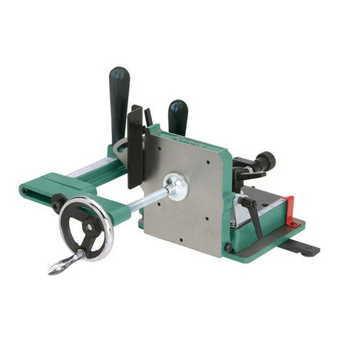
Power Tec 71402 User manual

Owner's Manual
Model No.71402
Bench Top Router Table and Fence
22-0914
You will need this manual for safety instructions, operating procedures, and warranty.
Put it and the original sales invoice in a safe, dry place for futurereference.
Visit us on the web at www.powertecproducts.com

RECOMMENDED ROUTER BIT SPEEDS
BIT DIAMETER MAXIMUM SPEED
Up to 1" (25 mm) ......................22,000 -24,000 rpm
1" to 2" (25 mm–51 mm) ................18,000-22,000 rpm
2" to 2-1/2" (51 mm–64 mm) ............12,000-16,000 rpm
2-1/2" to 3-1/2" (64 mm–89 mm) ..........8,000-12,000 rpm
NOTE: Always follow bit manufacturer’s speed
recommendations. Some bit designs require specific speeds for
safety or performance.
TABLE OF CONTENTS PRODUCT SPECIFICATIONS
SECTION PAGE
SAFETY RULES / WARNINGS 1-3
General Tool Safety
Tool Specic Warnings
PARTS AND CONTENTS 4
Assembly Parts
ASSEMBLY 5-9
Table Assembly
Fence Assembly
OPERATION 10-11
General Routing
MAINTENANCE 11
General Maintenance
NOTES 12
WARRANTY 13

SAFETY RULES 1
SAFETY RULES
1
WARNING
For your own safety, read all of the rules and precautions before
operatingtool.
WARNING
Always follow proper operating procedures as dened in this
manual even if you are familiar with use of this bench top
router table or any tool used with this bench top router table.
Remember that being careless for even a fraction of a second
can result in severe personal injury.
Before using another tool with this product, always read,
understand and follow the instructions and safety warnings in
the owner’s manual for that tool. If you do not have the owner’s
manual, obtain one from the tool’s manufacturer before using it
with this product.
You must be familiar with the use of any tool or accessory used
with this bench top router table. The supplier cannot be held
responsible for any accident, injury or damage incurred while
using this bench top router table with any tool.
It is the responsibility of the purchaser of this product to
ensure that any person using this product reads and complies
with all instructions and safety precautions outlined in this
manual prior to use.
WARNING
Some dust created by operation of power tools can expose
you to chemicals known to the State of California to cause
cancer, birth defects or other reproductive harm. To reduce your
exposure to these chemicals, work in a well ventilated area and
work with approved safety equipment. Always wear OSHA/
NIOSH approved, properly tting face mask or respirator when
using such tools.
CAUTION
Do not modify or use this bench top router table for any
application other than that for which it was designed.
FOLLOW ALL STANDARD SHOP SAFETY
PRECAUTIONS, INCLUDING:
• Keep children and visitors at a safe distance from work area.
• Keep work area clean. Cluttered work areas invite accidents.
Work area should be properly lit.
• Do not use power tools in dangerous environments. Do not
use power tools in damp or wet locations. Do not expose
power tools to rain.
• Wear proper apparel. Do not wear loose clothing, gloves,
neckties, rings, bracelets or other jewelry which may get
caught in moving parts of the tool.
• Wear protective hair covering to contain long hair.
• Wear safety shoes with non-slip soles.
• Wear safety glasses complying with United States ANSI
Z87.1. Everyday glasses have only impact resistant lenses.
They are NOT safety glasses.
• Wear face mask or dust mask if operation is dusty.
• Be alert and think clearly. Never operate power tools when tired,
intoxicated or when taking medications that cause drowsiness.
• A guard or any other part that is damaged should be properly
repaired or replaced. Do not perform makeshift repairs.
• Use the right tool for your job. Do not force your tool to do a
job for which it was not designed.
• Use safety equipment such as featherboards, push sticks and
push blocks, etc., when appropriate.
• Maintain proper footing at all times and do not overreach.
• Do not use the router table as a step or seat.
WARNING
• To avoid serious injury, turn off and unplug the router before
attaching the router base, changing accessories or adjusting
the cutter height/fence position.
• Assemble the featherboard(s) at least 1" (2.5 cm) from the
router bit to prevent kickback.
• Do not use the featherboard as a push block.
CAUTION
Think safety! Safety is a combination of operator common sense
and alertness at all times when tool is being used.
WARNING
Do not use the bench top router table until it is completely
assembled and you have read and understood this entire
operating manual and the operating manual of the tool being
used with this bench top router table.
SAVE ALL WARNINGS AND INSTRUCTIONS
FOR FUTURE REFERENCE

SPECIFIC SAFETY WARNINGS
2
DANGER
• To avoid serious injury, keep hands and ngers away from the
spinning router bit. Be aware of the bit at alltimes.
WARNING
AVOID THIS SITUATION!
• NEVER FEED YOUR WORKPIECE BETWEEN THE BIT AND
THE FENCE. Because of the direction of the bit’s rotation,
the bit could “grab" the workpiece and propel it away from
the table at a high velocity, potentially resulting in property
damage and serious injury to anyone in itspath.
• When the bit grabs the workpiece, your hands could be
drawn into the bit, resulting in serious injury
CAUTION
• Read, understand, and follow your router manufacturer’s
safety warnings andinstructions.
• Turn off and unplug your router before installing or
adjusting the bit or adjusting the bench top router table
and accessories. Never adjust the fence, plate, reducing
rings, or any part of the router or router table while the router
is running.
• Place the router table on a flat surface to prevent tipping
or sliding. Never stand on the router table.
• Set the bit guard directly over the router bit, at least
1/2" above the top of the bit or the top of the workpiece
(whichever is highest), make sure the bit doesn’t cut into
the bitguard.
• When adjusting the position of the fence, make sure no
part of the aluminum fence will contact the routerbit.
• Do not attempt to rout warped, twisted, or bowed
workpieces. All workpieces must have at faces and
square edges.
• Do not attempt to rout very large workpieces on a router
table. Very large workpieces can be difcult to control and
can cause the router table to tipover.
• Only use router bits in your router. Never use tools such as
carving burrs, mounted abrasives, wire wheels, or drill bits,
even if the shanks match the diameter of the router collet.
• Wear gloves when handling router bits.
Cutting edges aresharp.
• Never use dirty, dull, or damaged router bits. Remove
wood-resin build-up with a cleaner specically formulated for
cutting tools. Have dull bits sharpened by a qualied person.
Discard damaged bits.
• Make sure at least 75% of the router-bit shank length is
securely held in the router collet. To ensure a secure hold,
leave 1⁄16" to 1⁄8" (2mm-3mm) between the end of the bit
shanks and the bottom of the collet.
• Use the insert-plate reducing ring with the smallest
opening that allows the bit to pass through it. A large gap
around the bit can allow the workpiece to tip into the bit and
kickback.
• Position the fence faces as close as possible to the bit.
Turn the bit by hand to check for interference. Firmly tighten
the fence face knobs before routing.
• Adjust router speed to match the diameter of the bit.
Reduce router speed when using large-diameter bits.
See Recommended Router Bit Speeds for recommended
routerspeeds.
• Make sure the router motor is securely clamped in the
base before starting therouter.
• Always support the workpiece with the fence or start pin.
Only use the starter pin with router bits that have a guide
bearing. Failure to use these guides diminishes your ability
to control the workpiece and greatly increases the chance of
damage to the workpiece and/or serious personalinjury.
• When using the fence, always position the bit guard over
the router bit and as close to the workpiece surface
aspossible.
• Never remove a large quantity of stock in one cut. Make
several progressively deeper cuts, adjusting the router bit or
fence position betweencuts.
• Keep hands away from the rotating bit and your body out
of the path of the cut. Always use the bit guard, Use push
sticks, push blocks, and feather boards whenever possible,
especially when routing narrow workpieces. Turn off the router
before clearing parts ofscrap.
• Avoid awkward hand positions, where a sudden slip could
cause contact with the rotating bit. Neveroverreach.
• Avoid routing small parts. Rout the prole on a large
workpiece and then cut the part to nal size from the large
workpiece. If you must rout a small part, build an appropriate
jig or hold the part with a wood handscrewclamp.
• Make sure the workpiece is clear of the bit and the bit
comes to a complete stop before adjusting the workpiece
position. Never start the router with the workpiece in contact
with thebit.
• Avoid kickbacks. Kickbacks occur when the workpiece
binds or lifts off the table while being routed, causing it to
be thrown back toward the operator. To avoid kickbacks
and potential injury, use sharp bits, keep the machine
aligned and maintained properly, and adequately support
the workpiece. Do not attempt to rout workpieces that are
twisted, warped, or bowed, or that have looseknots.
2
SAFETY RULES

SAFETY RULES
3
• NEVER trap a workpiece between the bit and the fence.
When forming a prole on the straight edge of a workpiece,
always rout with the bit housed in the fence and the edge of
the workpiece against thefence.
• Whenever routing a profile in which material is not being
removed below a protruding portion of the bit, or a part of
the profile is trapped between cutters above and below,
take extra precautions to prevent the workpiece from
lifting off the table surface during routing. A workpiece
lifting off the table can kick back and cause serious personal
injury. When routing these proles, it is especially important
to use straight, at stock and avoid warped, bowed, or
twistedstock.
• Always feed the workpiece against the rotation of the bit.
A table-mounted router spins the bit counterclockwise, so
feed the workpiece from right to left as you face the table.
This provides better control because the rotation of the bit is
backward and toward the fence instead of forward and away
fromit.
• BEFORE plugging in and turning on the router, always make
sure the MDF adjustable fence faces are fully secured and
the bit can rotate freely without touching the fence faces. An
exception to this is if the infeed fence face is set to provide
zero-clearance support for the workpiece, as described in the
Adjusting the FenceFaces.
• Periodically check the tightness of fasteners and
adjustment and locking knobs and the alignment of the
fence. Loose fasteners and knobs and a misaligned fence
can cause personalinjury.
• This router table is designed for a specific application. Do
not modify and or use it for any other application. If you have
questions relative to the application of the router table, DO
NOT use it until you have contacted POWERTEC and have
been advisedaccordingly.
Guidelines for using extension cords
Extension cords are only to be used for temporary purposes.
They do not replace the need for installation of outlets and
proper wiring wherenecessary.
Make sure your extension cord is in good condition. When using
an extension cord, be sure to use one heavy enough to carry the
current your product will draw. An undersized cord will cause a
drop in line voltage resulting in loss of power and overheating.
The table below shows the correct size to be used according
to cord length and nameplate ampere rating. When in doubt,
use a heavier cord. The smaller the gauge number, the heavier
thecord.
AMPERAGE
@120
EXTENSION CORD LENGTH
25' 50' 175' 100' 150' 200'
RECOMMENDED WIRE GAUGE
0–5 16 16 16 14 12 12
5.1–8 16 16 14 12 10 NR
8.1–12 14 14 12 10 NR NR
12.1–16 12 12 NR NR NR NR
NR=Not Recommended
• Extension cords with an equipment grounding conductor
must be used at alltimes.
• Make sure your extension cord is properly wired and in good
condition. Always replace a damaged extension cord or have
it repaired by a qualied person before usingit.
• Protect your extension cords from sharp objects, excessive
heat and damp/wetareas.
• Extension cords must be a minimum of 16 AWG and be rated
for the equipment inuse.
• Use a separate electrical circuit for your tools. This circuit
must not be less than a #12 wire and should be protected
with a 15A time-delayed fuse. Before connecting the motor
to the power line, make sure the switch is in the OFF position
and the electric current is rated the same as the current
stamped on the motor nameplate. Running at a lower voltage
will damage themotor.

ASSEMBLY PARTS AND CONTENTS
4
4
ASSEMBLY
4
UNPACKING
Check for shipping damage. Check immediately whether all parts and accessories areincluded.
Table Assembly Refer to Figure 1
Shows the contents off the table assembly
ITEM DESCRIPTION QTY
AA Legs 4
BB Long Tie Bars (26" long x 2-3/4" wide with
two 3/4" anges 2
CC Short Tie Bars (18" long x 2-3/4" wide
with two 3/4" anges) 2
DD Carriage Bolts 5/16"-18 x 3/4" 16
EE Nuts 5/16"-18 16
FF Lock Washers 5/16" 16
GG Table Top (15-3/4" wide x 23-5/8" long x 1" thick) 1
HH Hexagon set screw 1/2"-20*25LX
(3/8"- 24 internal thread) 4
II Hex nut 1/2"-20 4
JJ Adjustment screw 3/8"-24
(1/4"-20 internal thread) 4
KK Hex nut 3/8"-24 4
LL Stri-head locking screw (1/4"-20) 4
MM Main Resin Insert 1
NN Reducing Rings
(Includes solid insert, 1" & 2-5/8" opening) 3
OO Screw M3P0.5 x 8mm 3
PP M5 Starting pin with M6 Insert (0609, 0610) 1
QQ
Screw 3/16" x 5/8" L
8
Figure 1
Fence Assembly Refer to Figure 2
Shows the contents off the fence assembly
ITEM DESCRIPTION QTY
A Fence 1
BFence lock knobs 5/16"-18 2
CWashers 5/16" 2
DT-Bolt 5/16"-18 x 1-1/ 2" 4
EMDF adjustable fence faces 2
FFlat head screws 1/4"-20 x 1-1/2" 4
GWing Knobs, 1/4"-20 6
HBit guard 1
IT-Bolts 1/4"-20 x 1" 2
JNylon Washer 1/4" 2
KRouter dust port 1
LPan head screws M4 x 10 mm 2
MWashers 1/4" 2
NFeatherboard 1
ONylon Spacers 2
PTape measure with adhesive backing
(right to left)
1
Q3" Flip stop 1
R4 mm Round Rods 2
S1/4" Square Rods 2
TWing Knobs, 5/16"-18 2
Figure 2

TABLE ASSEMBLY 5
TABLE ASSEMBLY
5
ASSEMBLE BENCH TOP ROUTER TABLE
Model No. 71402
Top (with wood top) A 23-5/8" x 15-3/4" (600x400mm)
Leg Spacing B 27-1/8" x 19-1/4" (689x489mm)
Height (with wood top) C 15-1/2" (394mm)
Shelf 23-5/8" x 15-3/4" (600x400mm)
Shelf Height 14-1/2" (369mm)
WARNING
Refer to Figure 3–10
Do not use the bench top router table until it is completely
assembled and you have read and understood this entire
operating manual and the operating manual of the tool being
used with this bench top routertable.
Figure 3
1. Attach short tie bar(CC) to each pair of legs (AA) using
carriage bolts 5/16"-18 x 3/4" (DD), lock washers 5/16" (FF)
and nuts 5/16"-18 (EE). Finger tighten thenuts.
Figure 4
2. Attach short rail/leg assembly to each long rail (BB) using
four carriage bolts 5/16"-18 x 3/4" (DD), lock washers 5/16"
(FF) and nuts 5/16"-18(EE). Finger tighten thenuts.
Figure 5
3. Hand tighten Adjustment screw (JJ) into the hexagon set
screw (HH). Place the assembly into the holes in the insert
opening and tighten hex nut (I I) against the bottom of the
table. Place hex nut (KK) onto adjustment screw (JJ). DO
NOT tighten at this time. Repeat for all four holes.
Figure 6
4. Place leg assembly upside down (Figure 6) then position onto
bottom of assembled table top. Align holes in top of each
leg with pre-drilled pilot holes in the table. Fasten the Leg
assembly to the top with eight 3/16" coarse-thread screws
(QQ) Use handheld screw driver to prevent stripping screws.
Do not overtighten.
5. Turn the assembly right-side up and tighten all sixteen nuts
(EE) on leg/rail assembly.

6
TABLE ASSEMBLY
Router Drill Patterns
Figure 7
1. Insert plate (MM) has lettered center points molded into
the bottom face using drill patterns for the most common
routers. Locate your router on the following chart and use
the lettered pattern indicated. Drill a hole matching the size
of the mounting screws supplied with your router. Once the
holes are drilled, ip the insert plate over and counter bore,
or counter sink the drilled holes to seat the mounting screws
below the surface of the mounting plate.
NOTE: Drill holes and counterbores or countersinks to
accommodate the mounting screws supplied with the router. For
routers equipped with a built-in lift system, use the router sub-
base as a guide for the location and size of the access hole and
as a drillingguide.
PORTER
CABLE*
A690 Series A8529
A7529
DEWALT* FDW621 ADW616 Series
FDW625 ADW618 Series
Craftsman*
C315 275 000 E315 175 060
D315 175 040 D315 175 070
D315 175 050
Bosch* A1617 (fixed base) A1618
G1617 (plunge base) AMR23 Series
Makita* A RF1101
Ryobi* C R1631K
Milwaukee* A5615 A5616
A5619
Fein* F FT 1800
Elu* F 177
Hitachi* A M-12VC
* PORTER-CABLE, DEWALT, Craftsman and Elu are trademarks of The Stanley
Black & Decker Corporation—Bosch is a trademark of the Robert Bosch Tool
Corporation—Makita is a trademark of Makita Corporation—Ryobi is a trademark
of Ryobi Limited and is used by Techtronic Industries Company LTD—Milwaukee
is a trademark of Techtronic Industries Company LTD—Fein is manufactured by C.
& E. Fein GmbH—Hitachi is a trademark of Hitachi, Ltd.
For routers not covered by the Chart follow the
instructions below
With target pattern facing up—place insert plate (MM) onto
workbench. (Figure 8)
a. Remove sub-base from router. Check router base holes to
ensure alignment with any of the center point patterns. If so,
use that pattern.
b. If no existing patterns match up, select a drill bit that ts the
mounting holes of your subbase. If router is equipped with a
built-in lift system, select a bit that ts the lift-access hole.
c. Apply several small pieces of double-faced tape to the insert
plate. Now, center the sub-base on the plate, using the
concentric arcs of the target pattern as guides.
d. Keep in mind preference of router control position. Check
that holes to be drilled align with the threaded hole for the
start pin or the predrilled center points. Press the subbase
rmly onto the insert plate.
NOTE: Before drilling, securely clamp the insert plate to
drill-press table or bench to prevent movement while drilling.
Whether using a drill press or hand drill, place a wood scrap
under the insert plate to reduce chipping as the drill bit passes
through the plate. Performing this operation on a drill press
ensures the holes will be perpendicular to the plate.
e. Use the holes in the sub-base as a pattern and mark the
needed holes, drill the holes in the insert plate with a drill
press or hand drill.
Figure 8
Figure 9
f. With holes drilled, remove sub-base from insert plate. Flip
plate over and countersink mounting holes assuring machine
screw heads sit below plate surface when tightened.

TABLE ASSEMBLY
7
IMPORTANT: Store the router sub-base in a convenient place.
It will be needed when removing router from the router table and
for handheldrouting.
2. Using the screws that attached the sub-base to the router,
attach the router base to the insert plate (MM).
NOTE: Depending on the thickness of your router sub-base, it
may be necessary to purchase longer screws. Make certain that
the screws are long enough to fully thread into the router base.
If you are mounting a fixed-base router, install the motor unit in
the routerbase.
Figure 10
3. Place the insert plate, with the router attached, into the table
opening, resting it on the adjustment screws (JJ). Using an
M6 hex wrench, adjust the adjustment screws through the
holes in the insert plate. Use a straight edge to verify the
insert plate is ush with the tabletop. Once ush, tighten nuts
(KK). If not ush, ne-tune the adjustment screws until the
insert plate is ush with the tabletop.
4. Thread the four at head screws (LL) through the
countersunk holes in the insert plate and into the center
hole on each adjustment screws and tighten, locking the
insert plate in place. Some adjustment of the lock down
screws and adjustment screws may be necessary to ne-
tune the alignment.
5. Choose the reducing ring appropriate for the job and attach
it to the insert plate using the three set screws (OO). When
needed, thread the starting pin (PP) into the threaded hole in
the insert plate and tighten.

FENCE ASSEMBLY
8
8
FENCE ASSEMBLY
Figure 11 BACK
Refer to Figure 11–13
• Remove the adhesive backing from the right to left tape
measure and press into place. Start on the right end and
carefully place the tape along the front edge of the fence.
Use scissors to cut the excess tape from the leftend.
• Attach the dust port to the back of the fence using the pan
head screws and 1/4"washers.
• From the front of the MDF adjustable fence faces, insert the
1/4"-20 x 1-1/2" screws through the MDF adjustable fence
face and fence, secure in place with the locking knobs. The
MDF adjustable fence faces can be adjusted left or right, after
adjustment has been made for the operation to be performed,
tighten all knobssecurely.
• From the bottom of the fence insert the two 5/16"-18 x 1-1/2"
T-Bolts through the fence slot. Place a 5/16" washer and
fence locking knob on each T-Bolt. Place the fence onto the
router table and align the T-Bolts in the fence with the slots in
the router table. Tighten the knobs after adjusting the fence to
the operation beingpreformed.
• From the back of the bit guard insert two 1/4"-20x 1" T-Bolts,
place 1/4" washers and locking knobs onto each T-Bolt. Place
the T-Bolts into the T-Slot on the face of the fence and slide
the bit guard onto the fence. NOTE: To adjust the bit guard,
loosen the knobs, slide the bit guard up and down to desired
application and tighten knobs. When changing bits, slide the
bit guard left or right of theopening.
WARNING
To prevent kickback make sure the featherboard is at least
1" (2.5 cm) from the cutter.
• Place a spacer on each 5/16"-18 x 1-1/2" long T-Bolt and insert
through the slot in the featherboard, thread a locking knob on
each T-Bolt and slide the T-Bolts into the T-slot in the front of
the fence. Position the featherboard and tighten lockingknobs.
• Slide the T-Bolt on the ip stop into the T-Slot in top of the
fence, tighten the knob. The arm on the ip stop functions
as an easily adjustable stop and can be ipped up when not
needed. NOTE: The ip stop is multi-functional, please see
ip stop instructions for details. To prevent chip build up, the
stop does not extend the full width of the fence. However
when using a stop with material 3/8" thick or less, a longer
stop will need to be fabricated and can be mounted in the
T-slot located in the front of thefence.
IMPORTANT: Every routing operation is different, adjust the
various parts of the router fence and accessories as needed and
then tighten all knobssecurely.
To Convert from Inboard to Outboard Position
Remove the knob and T-bolt and rotate the stop body 180°.
Replace the knob and T-bolt. See below

FENCE ASSEMBLY
9
Figure 13
4. Tighten the locking knobs on the back of the MDF adjustable
fence face to secure it in position.
Figure 14
ADJUSTING THE FENCE FACES
Refer to Figure 14
The two MDF adjustable fence faces are designed to slide about
2" along the fence. This allows the opening for the router bit to
be adjusted from 0" up to4".
Generally, the infeed and outfeed adjustable fence faces should
be adjusted as close to the bit as possible without contacting
the cutter. This will help prevent the ends of the workpiece from
drifting too far into the cutter at the beginning and end of the cut
to provide quality and safecut.
Sometimes the “zero-clearance" support is needed to deliver
an even cleaner cut. In this case the router bit prole cuts into
the front edge of the infeed adjustable fence face so there
is virtually no gap between the cutter and the fence face. It
delivers a cleaner cut because the workpiece bers are fully
supported throughout thecut.
If a zero clearance setting is necessary, follow these steps:
1. Set the bit height and fence position. Set both of the MDF
adjustable fence faces close to the bit without touching it, the
fence faces MUST NOT contact the bit at thistime.
CAUTION
Set the bit guard directly over the router bit, at least 1/2" above
the top of the bit or the top of the workpiece (whichever is
highest), make sure the bit doesn’t cut into the bit guard.
2. Install, adjust and secure the bit guard.
3. On the back of the fence, slightly loosen locking knobs on
infeed MDF adjustable fence face. Start the router and slowly
slide infeed MDF adjustable fence face into the spinning
router bit, stopping when the edge reaches the bit’s guide
bearing or midpoint (for bits that don’t have a guide bearing).
Figure 12 FRONT

GENERAL ROUTING
10
10
GENERAL ROUTING
ROUTING
1. Use the insert-plate reducing ring with the smallest opening
that allows the bit to pass through it. Position the fence faces
as close as possible to the bit. Turn the bit by hand to check
forinterference.
2. Firmly tighten the fence-face Wing Knobs before routing.
Position the bit guard over the router bit and as close to the
workpiece surface as possible.
3. Feed the workpiece against (not with) the bitrotation.
REDUCING RINGS
Figure 15
There are three reducing rings for exibility in matching the size
of the insert opening to the diameter of the router bit in use;
a solid insert, to be bored for any custom size, an insert with
a 1" opening, and an insert with a 2-5/8" opening. To install a
reducing ring, simply drop it into the insert-plate opening and
attach using the three M3 set screws (OO)
NOTE: The ring with the rabbeted opening accepts standard
Porter- Cable style guide bushings, allowing you to use your
router table for patternrouting.
STARTING PIN
To use the starting pin, begin with your workpiece touching
the pin, but not in contact with the router bit. Slowly pivot
the workpiece into the bit until the workpiece makes contact
with the bit guide bearing. Always feed the workpiece so the
router bit rotates against (not with) the feed direction. With the
workpiece in solid contact with the guide bearing, ease the
workpiece off of the starting pin and feed the workpiece against
the guidebearing.
WARNING
Use the starting pin when routing along curved edges and only
with router bits that have a guide bearing. When routing along
straight edges, always use thefence.
JOINTING
Refer to Figure 16–19
The independently adjustable fence faces allow the router table
to be used as a vertical jointer by offsetting the outfeed fence
face 5/64", 1/16", 3/128" from the infeed fenceface.
Two sets of grooves are located in the fence behind the fence
faces, slide the jointing rods into these grooves to offset
the outfeed fence face 5/64", 1/16", 3/128" from the infeed
fenceface.
NOTE: It is best to make light passes when jointing, the
3/128" and 1/16" offset will be used more frequently than the
5/64"offset.
1. Loosen the locking knobs securing the outfeed fence face.
Slide the jointing rods into the desired groove on the fence.
a. For a 5/64" offset—Slide square jointing rods into the
square grooves on the outfeed fence. Figure 16.
b. For a 1/16" offset—Slide round jointing rods into the
roundgrooves on the outfeed fence. Figure 17.
c. For a 3/128" offset—This is the only setup using both sets
of jointing rods. Slide square jointing rods into the square
grooves on the OUTFEED fence. Slide round jointing rods into
the round grooves on the INFEED fence. Figure 18.
Figure 16 Figure 17
Square jointing rods shown
in the square grooves for the
5/64" offset.
Round jointing rods shown
in the round grooves for the
1/16" offset.
Figure 18
Square jointing rods shown in the square grooves on the
OUTFEED fence. Round jointing rods in the round grooves on
the INFEED fence for the 3/128" offset.
2. With the rods in place, tighten the fence face lockingknobs.

MAINTENANCE 11
GENERAL ROUTING
11
MAINTENANCE
11
Figure 19-b (Top View with workpiece)
Always use a scrap piece of wood to test thesetup.
• If the scrap is fed past the bit and it runs into the leading end
of the outfeed fence face, the fence is too far forward and
not enough material is being removed. Move the fence back
alittle.
• If there is snipe at the trailing edge of the scrap, the fence is
too far back and too much material is being removed. Move
the fenceforward.
Figure 19-a
3. Install a straight bit in the router. Place a straight edge against
the outfeed fence face and position the fence so the bit just
grazes the straight edge.
NOTE: Make sure all rods are clear of cutter.
NOTE: Any straight bit can be used for jointing. A flush-trim
bit is the easiest to set up because the bit guide bearing is the
same diameter as the cutter and it can be aligned to the outfeed
fence face with the bearing. An up-cut spiral bit produces an
almost chatter-free surface, but it is more difficult to align with
the fenceface.
GENERAL MAINTENANCE
WARNING
When servicing, use only identical replacement parts. Use of
any other parts may create a hazard or cause product damage.
To ensure safety and reliability, all repairs should be performed
by a qualied servicetechnician.
WARNING
Keep the bench top router table dry, clean, and free from oil
and grease. Always use a clean cloth when cleaning. Never use
brake uids, gasoline, petroleum based products or any strong
solvent to clean the bench top router table. Chemicals can
damage, weaken or destroy plastic which may result in serious
personalinjury.

NOTES
12
12
Notes

WARRANTY 13
WARRANTY
13
Thank you for investing in a POWERTEC power tool. This product has been designed and manufactured to meet high
quality standards and is guaranteed for domestic use against defects in workmanship or material for a period of 12
months from the date of purchase. This guarantee does not affect your statutory rights.
SOUTHERN TECHNOLOGIES LLC. BENCH TOP AND STATIONARY POWER TOOL
LIMITED 1 YEAR WARRANTY AND 30-DAY SATISFACTION GUARANTEE POLICY
POWERTEC products are designed and manufactured by Southern Technologies LLC. All warranty communications
should be directed to Southern Technologies LLC by calling 847-780-6120 (toll free), 9 AM to 5 PM, Monday through
Friday, US Pacic Time.
30-DAY SATISFACTION GUARANTEE POLICY
During the rst 30 days after the date of purchase, if you are dissatised with the performance of this POWERTEC tool
for any reason, you may return the tool to the retailer from which it was purchased for a full refund or exchange. You
must present proof of purchase and return all original equipment packaged with the original product. The replacement
tool will be covered by the limited warranty for the balance of the one year warranty period.
LIMITED ONE YEAR WARRANTY
This warranty covers all defects in workmanship or materials in this POWERTEC tool for a one year period from the
date of purchase. This warranty is specic to this tool. Southern Technologies, LLC reserves the right to repair or
replace the defective tool, at its discretion.
HOW TO OBTAIN SERVICE
To obtain service for this POWERTEC tool you must return it, freight prepaid, to POWERTEC. You may call (toll
free) 847-780-6120 for more information. When requesting warranty service, you must present the proof of purchase
documentation, which includes a date of purchase. POWERTEC will either repair or replace any defective part, at
our option at no charge to you. The repaired or replacement unit will be covered by the same limited warranty for the
balance of one year warranty period.
WHAT IS NOT COVERED
This warranty applies to the original purchaser at retailer and may not be transferred.
This warranty does not cover consumable items such as saw blades, knives, belts, discs, cooling blocks and sleeves.
This warranty does not cover required service and part replacement resulting from normal wear and tear, including
accessory wear.
This warranty does not cover any malfunction, failure or defect resulting from:
1) misuse, abuse, neglect and mishandling not in accordance with the owner’s manual.
2) damage due to accidents, natural disasters, power outage, or power overload.
3) commercial or rentaluse.
4) alteration, modication or repair performed by persons not recommended by POWERTEC.
DISCLAIMER
To the extent permitted by applicable law, all implied warranties, including warranties of MERCHANTABILITY or
FITNESS FOR A PARTICULAR PURPOSE, are disclaimed. Any implied warranties, that cannot be disclaimed under
state law are limited to one year from the date of purchase. Southern Technologies LLC. is not responsible for direct,
indirect, incidental or consequential damages. Some states do not allow limitations on how long an implied warranty
lasts and/or do not allow the exclusion or limitation of incidental or consequential damages, so the above limitations
may not apply to you. This warranty gives you specic legal rights, and you may also have other rights which vary from
state to state. Southern Technologies LLC., makes no warranties, representations, or promises as to the quality or
performance of its power tools other than those specically stated in this warranty.

Southern Technologies, LLC
Chicago, IL 60606
Table of contents
Other Power Tec Tools manuals

Power Tec
Power Tec 80027 User manual

Power Tec
Power Tec 91781 User manual

Power Tec
Power Tec 71685 User manual

Power Tec
Power Tec 80002 User manual

Power Tec
Power Tec 71767 User manual

Power Tec
Power Tec 71845 User manual

Power Tec
Power Tec 71643 User manual

Power Tec
Power Tec 71399 User manual

Power Tec
Power Tec 71765 User manual

Power Tec
Power Tec 70316 User manual