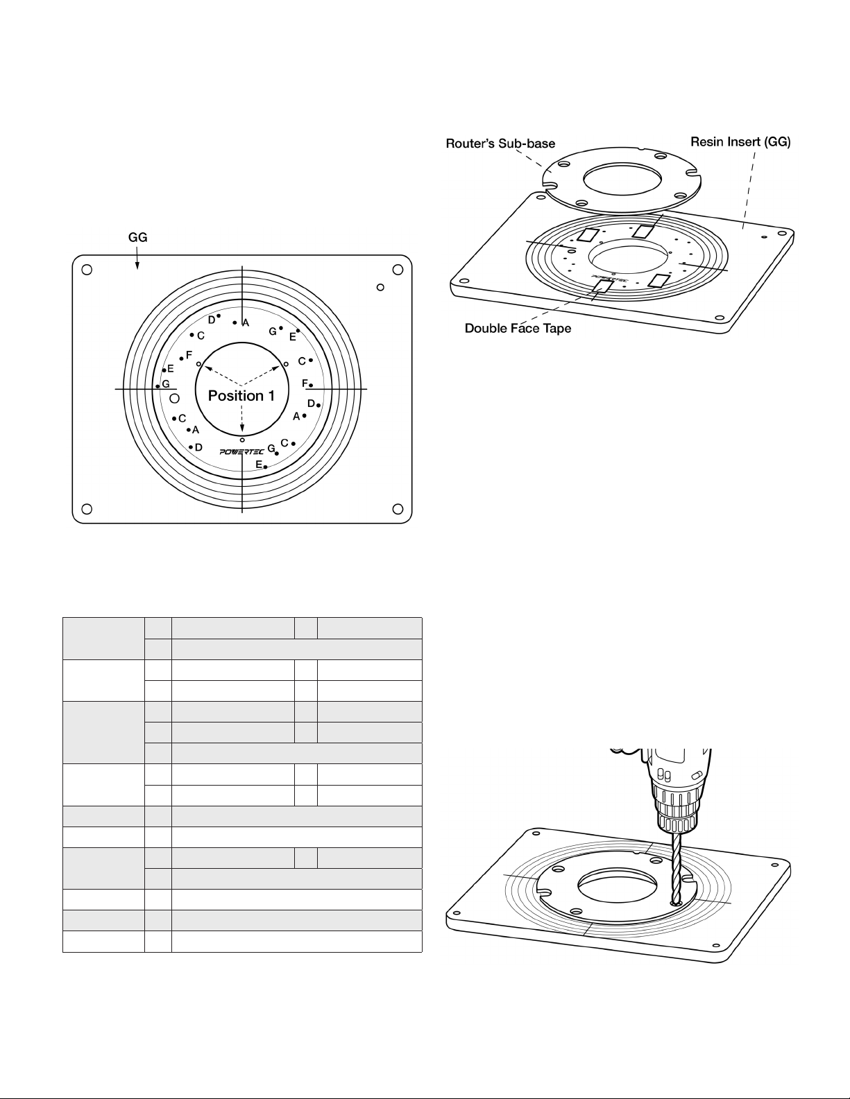
REDUCING RINGS
See Figure 8. There are three reducing rings for exibility in
matching the size of the insert opening to the diameter of the
router bit in use; a solid insert, to be bored for any custom size,
an insert with a 1" opening, and an insert with a 2‑5/8" opening.
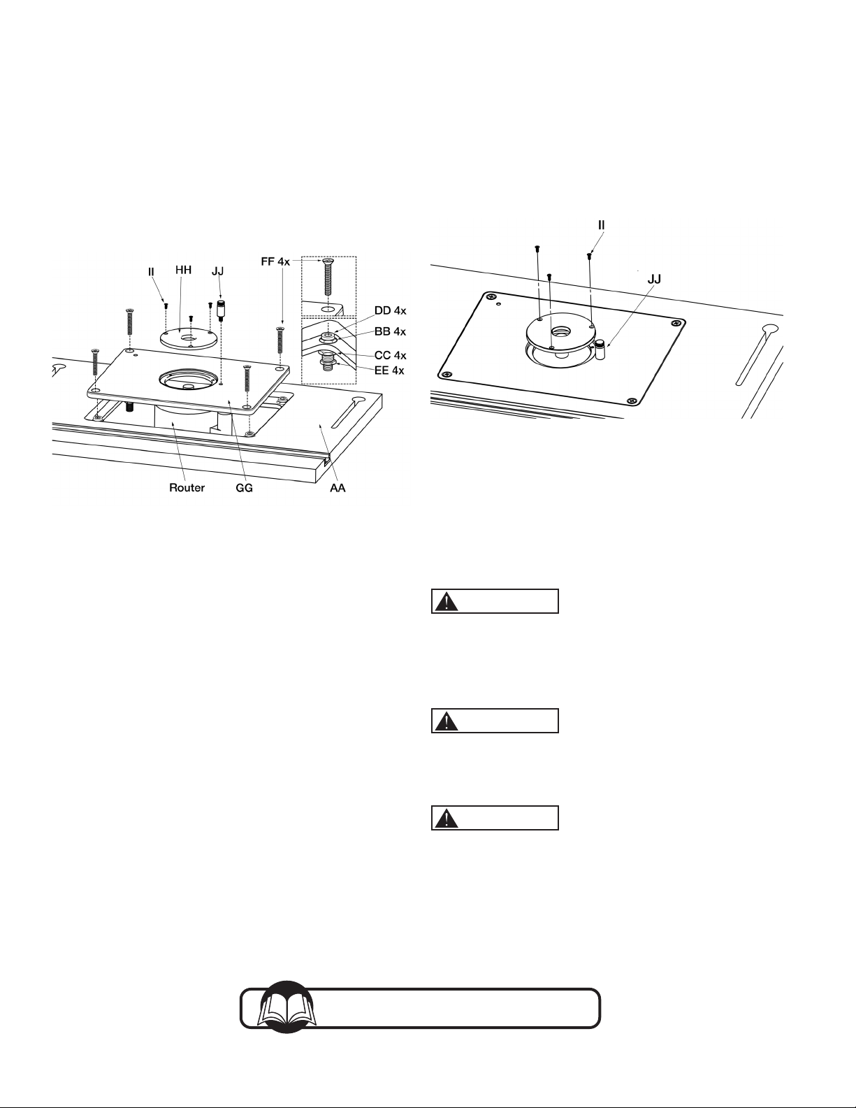
To install a reducing ring, simply drop it into the insert‑plate
opening and attach using the three M3 set screws (II) with the
3mm Screwdriver (MM) provided.
Figure 8
STARTING PIN
To use the Starting Pin (JJ), begin with your workpiece touching
the pin, but not in contact with the router bit. Slowly pivot
the workpiece into the bit until the workpiece makes contact
with the bit guide bearing. Always feed the workpiece so the
router bit rotates against (not with) the feed direction. With the
workpiece in solid contact with the guide bearing, ease the
workpiece off of the starting pin and feed the workpiece against
the guidebearing.
WARNING
Use the starting pin when routing along curved edges and only
with router bits that have a guide bearing. When routing along
straight edges, always use thefence.
GENERAL MAINTENANCE
WARNING
When servicing, use only identical replacement parts. Use of
any other parts may create a hazard or cause product damage.
To ensure safety and reliability, all repairs should be performed
by a qualied servicetechnician.
WARNING
Keep the Router Table Top dry, clean, and free from oil and
grease. Always use a clean cloth when cleaning. Never use brake
uids, gasoline, petroleum based products or any strong solvent
to clean the Router Table Top. Chemicals can damage, weaken or
destroy plastic which may result in serious personalinjury.
IMPORTANT: Store router sub-base in a convenient place.
It will be needed when removing router from router table and
during handling.
3. See Figure 7. Using the screws for attaching the sub‑base to
the router, attach router base to Resin Insert GG).
NOTE: Depending on the thickness of your router sub-base, it
may be necessary to purchase longer screws. Make certain the
screws are long enough to fully thread into the router base. If
you are mounting a fixed-base router, install the motor unit in the
routerbase.
Figure 7
4. Place Resin Insert (GG), with the router attached,
into Router Table Top (AA) opening, resting it on the
Adjustment Screws (DD). Using the M6 Hex Wrench (NN)
provided, adjust the adjustment screws through the holes in
the insert plate. Use a straight edge to verify the insert plate
is ush with the tabletop. Once ush, tighten Hex Nuts (EE).
If not ush, ne‑tune the adjustment screws until the insert
plate is ush with the tabletop.
5. Thread the four Flat‑head Screws (FF) through the
countersunk holes in the insert plate and into the center
hole on each adjustment screws and tighten, locking the
insert plate in place. Some adjustment of the lock down
screws and adjustment screws may be necessary to ne‑
tune the alignment.
6. Choose the reducing ring appropriate for the job and attach
it to the insert plate using the three Set Screws (I I). When
needed, thread the Starting Pin (JJ) into the threaded hole in
the insert plate and tighten.
Southern Technologies, LLC
Chicago, IL 60606
Put these instructions and the original sales invoice
in a safe, dry place for future reference.
Visit us on the web at www.powertecproducts.com