Power Test SuperFlow AutoDyn AD-30 User manual

SUPERFLOW AUTODYN AD-30
AWD CHASSIS DYNAMOMETER
PIT INSTALLATION

PI0030CS02
REV: 3.30.2020

AutoDyn AD-30 AWD Chassis Dynamometer
Safety Warnings ..........................................................................................................2
Dangers Due to Non-observance of Safety Instructions ...............................................................2
Document Conventions .....................................................................................................................2
Test Cell Room Requirements ...................................................................................3
Hazards of Dynamometer Testing ...................................................................................................3
Test Cell Design ..................................................................................................................................4
Pit Design .............................................................................................................................................6
Pit Drainage .........................................................................................................................................7
Ventilation ...........................................................................................................................................7
Combustion Air .............................................................................................................................................8
Heat Extraction ..............................................................................................................................................9
Vehicle Cooling............................................................................................................................................10
Exhaust Extraction.......................................................................................................................................11
Absorber Cooling and Pit Ventilation ......................................................................................................12
Vehicle Restraint Requirements .....................................................................................................13
Electrical Requirements ...................................................................................................................14
Dynamometer Chassis ................................................................................................................................15
Data Acquisition System ............................................................................................................................15
Miscellaneous...............................................................................................................................................15
Air Requirements .............................................................................................................................15
Static Electricity ................................................................................................................................16
Convenience Issues ..........................................................................................................................16
Equipment Recommendations .......................................................................................................17
Ventilation Fans ...........................................................................................................................................17
Air Handling ................................................................................................................................................19
Water Pumps and Accessories...................................................................................................................20
Vehicle Tie-down Accessories ...................................................................................................................20
Installation Instructions
Required Tools ..........................................................................................................22
Pit Preparation ...........................................................................................................22
Rollset Preparation ...................................................................................................23
Placing the AutoDyn in the Pit .................................................................................26
Eddy Current Absorber Module and Driveshaft .....................................................31
Plumbing and Wiring ................................................................................................33
Rollset Covers ...........................................................................................................36
Contents

Drawings and Schematics
AD-30 AWD Dimensions 41
AD30 AWD Pit Location 42
AD-30 AWD Pit Layout (page 1 of 4) 43
AD-30 AWD Pit Layout (page 2 of 4) 44
AD-30 AWD Pit Layout (page 3 of 4) 45
AD-30 AWD Pit Layout (page 4 of 4) 46
Vehicle Tie-down Points 47
AWD Cover Plate Locations 48
AWD Electrical Drawing 49
AWD AD-30 Junction Box Assembly 50
Eddy Current Assembly Drawing 51
Energy Balance (Metric Units) 52
AutoDyn Room and Pit Airflow (U.S. Units) 53
Drawings

Page 1 3.30.2020
Product
Information
AD-30 AWD Pit Installation
AutoDyn AD-30 AWD Chassis Dynamometer
SuperFlow AutoDyn dynamometers can be installed in a pit so vehicles can drive on and off the
rolls for testing. Pit installations have certain advantages over above-ground dynamometers—
particularly that it is safer and easier to position the test vehicles on the rolls.
All Wheel Drive (AWD) dynamometer are designed to be installed in a pit because of the required
additional supports for the covers in front of and between the dynamometer rolls.
• The pit is normally constructed of poured concrete with provisions for drainage and
ventilation. Access for control cables and electrical wiring is also required through conduits
or trenches.
• Vehicle tie-downs should be embedded in the concrete around the pit so the vehicle can be
secured on the rolls. A minimum of three tie-downs is required at each end of the vehicle.
Ideally, tie-down anchors should be spaced around the dynamometer to provide for most
any situation. More information on this is provided later in this document.
• Air flow must be provided in both the test room and the dynamometer pit. This is necessary
for vehicle cooling, room ventilation, exhaust extraction, and eddy current absorber cooling.

SuperFlow Product Information
AD-30 AWD Pit Installation 3.30.2020 Page 2
Safety Warnings
To ensure safe operation, this equipment must only be operated according to the
instructions in the SuperFlow Operator Manual. It is also essential that this equipment
is installed, maintained, and operated according to local safety requirements.
Any person instructed to carry out installation, maintenance or repair of the equipment must read
and understand the SuperFlow Operator Manual and in particular the technical safety instructions.
Any users of this equipment must operate only the controls of the equipment. Only qualified
personnel should remove exterior panels and service equipment.
1. Follow all local building and fire codes.
2. Do not locate water pumps or exhaust fan motors in close proximity where fuel is present.
3. Install a carbon monoxide (CO) detector in the test cell and the console area.
4. Provide fire extinguishers rated for gasoline and oils.
5. Provide adequate lighting in the test cell and at the computer console.
6. Provide a switch outside the test cell to turn off the ventilation fans and water pumps.
7. Always use hearing and eye protection when necessary.
8. Regularly inspect the cell for fuel, oil, or liquid spills because flammable vapors can ignite.
9. Keep all personnel, flammable items, and sensitive objects away from any rotating object that
can throw debris radially outward.
Dangers Due to Non-observance of Safety Instructions
• Hearing damage due to high noise level
• Electrical shock
• Exposure to rotating parts
Document Conventions
The following conventions indicate items of interest or concern:
WARNING: Failure to take or avoid a specific action could result in physical harm to the
user or the hardware.
CAUTION: Failure to take or avoid a specified action could result in loss of data or equipment.
IMPORTANT: Essential operating information.
NOTE: Helpful information that may provide insight to the user/operator.
TIP: Additional information that may provide convenient workaround or solution.
Cross-references refer the reader to additional information in the chapter, manual, or other
sources (including Web sites).

SuperFlow Product Information
AD-30 AWD Pit Installation 3.30.2020 Page 3
Test Cell Room Requirements
Notice
It is imperative that you understand dynamometer testing can be hazardous. A properly
designed and built test cell is a prerequisite to providing a safe environment for testing
vehicles.
While SuperFlow provides specific test equipment designed to test your vehicles, we have
no control over how you build your test cell. These room recommendations are general and
may not specifically be suitable for your particular location or application.
A locally certified engineer or contractor must approve your designs and certify that they
conform to local building codes. Your local governing body regulations and insurance
company policies will rule over any questions or uncertainties.
SuperFlow, its employees, or agents do not assume any responsibility or liability for
suggestions, applications, or mechanical failure outside of the normal warranty or for
issues where negligence, ignorance, or mis-applied technologies are present. Ultimately,
you are responsible for ensuring your test cell is safe and conforms to all local codes and
regulations.
Read this document in its entirety before beginning construction. Contact SuperFlow Sales or
Customer Service if you have any questions or need assistance.
Hazards of Dynamometer Testing
Dynamometer testing involves running internal combustion engines. Doing so exposes the
operator to rotating parts, fluids under pressure, explosive fuels, high voltages, noise, heat, and
exhaust gases. Chassis dynamometer testing has additional risks associated with rotating
transmission parts, wheels, and chassis rolls.
These risks are generally associated with the vehicle under test rather than the dynamometer. It is
not possible for SuperFlow to protect the operator against all hazards by the design of the
dynamometer. Therefore, the dynamometer must be installed in an environment which is
specifically designed for this type of testing and provides maximum protection for the operator.
IMPORTANT: Safety equipment required to provide maximum protection for the operator must be
readily available for dynamometer testing.
SuperFlow Product Information
AD-30 AWD Pit Installation 3.30.2020 Page 4
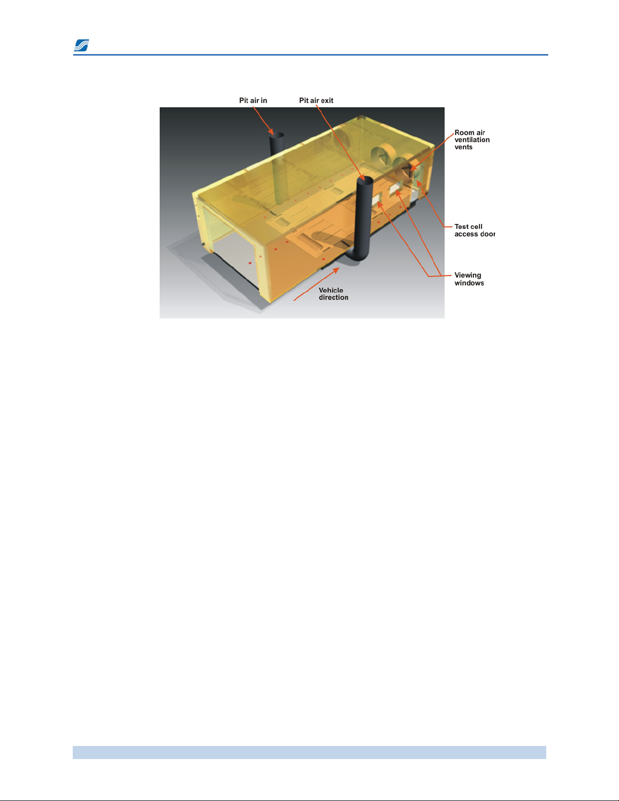
Test Cell Design
Figure 1. AutoDyn Test Cell
A dynamometer should be installed in a facility with proper lighting, electric power, compressed
air, good ventilation, exhaust extraction, and a fire detection system. There must be enough room
to easily install and remove the test vehicle. It should allow enough space to work on the vehicle
while it is in place on the dynamometer, yet small enough to take up minimal space in your
building.
A dedicated, separate room is not actually required for operation of the AutoDyn. However, a
properly built test cell provides protection, noise control, exhaust isolation, and directed cooling
of the test vehicle.
Figure 1 shows a setup where the vehicle is driven forward onto the dyno. The direction of travel
for the vehicle on the dynamometer is purely at the discretion of the system owner or test cell
designer. SuperFlow makes no distinction as to which is better—driving forward or driving
backward onto the dynamometer.
• Driving forward with the rear of the vehicle toward the access door makes it easier to
position the vehicle on the rollset. However, this means the ventilation fans are at the front
of the vehicle and will blow air through the room. This generally requires higher-capacity
fans to maintain proper ventilation and keep the room clear of dangerous exhaust gases.
• Backing onto a rollset and getting the vehicle straight can be difficult until the operator
gains experience. But having the ventilation fans sucking air at the back of the vehicle is
more efficient for moving air through all areas of the room and extracting errant exhaust
fumes, especially if you can produce a slight negative pressure in the room. This design
usually requires additional spot fans in front of the vehicle for cooling.
• A drive-through test cell is an ideal setup if the ventilation system can be designed around
having access doors at both ends of the room. These test cells generally operate with the rear
door closed and ventilation fans pulling air out of the room either through a ceiling vent or
through ducts on both sides of the rear door. This concept can also work for a drive-forward
design.

SuperFlow Product Information
AD-30 AWD Pit Installation 3.30.2020 Page 5
Proper airflow through the test cell is critical for engine cooling and room ventilation. Having a
larger test cell than necessary makes it difficult to control airflow through the cell and increases
the cost because of the need for larger air-handling equipment. A large room also increases
heating and cooling costs.
TIP: Prefabricated rooms are available as an option to building a room.
The room should be no larger than necessary to ensure high air velocity around the vehicle during
tests. The room should be long enough to accommodate a vehicle on the dynamometer and still be
able to close the main access door. This helps minimize building heating or cooling loss while not
actually testing the vehicle. Typically, the room should be 30 ft. [9 m] long, 15 ft. [4.5 m] wide with
a 10-ft. [3.0-m] ceiling.
Figure 2. AD-30 AWD Test Room Dimensions
A separate control room or dedicated viewing area overlooking the dynamometer can be part of
the test cell design. This room may be used to house the computer and printer, thus providing a
convenient and safe viewing area during testing. Avoid positioning the control room where an
object thrown from the vehicle may create a hazard.
When building a dynamometer test cell, consider the following:
• Provide viewing windows so observers can watch a test in progress from a safe vantage point.
Position the window so it does not align with possible objects thrown by the vehicles. The viewing
window can be part of the control room and is more effective if it is located on the driver side of
the vehicle.
•The rotating tires may throw rocks or debris, so do not locate any storage or equipment in line
with the direction of the tire rotation.
• All test room doors should open outward from the room, and all doors should be fitted with
appropriate door latches.
&&
3LW$LU([LW'XFW
6HH(QHUJ\%DODQFH:RUNVKHHW
IRUVL]LQJLQIRUPDWLRQ
3LW$LU QOHW'XFW
6HH(QHUJ\%DODQFH:RUNVKHHW
IRUVL]LQJLQIRUPDWLRQ
9HKLFOH'LUHFWLRQ
7HVW&HOO$FFHVV'RRU
)URQW&RYHUV6HFXUHGWR3LW(GJH
0RYDEOH6SRW&RROLQJ)DQWR6XSSOHPHQW
9HKLFOH&RROLQJDV1HFHVVDU\
0 1 0805(&200(1'('5220/(1*7+
SuperFlow Product Information
AD-30 AWD Pit Installation 3.30.2020 Page 6
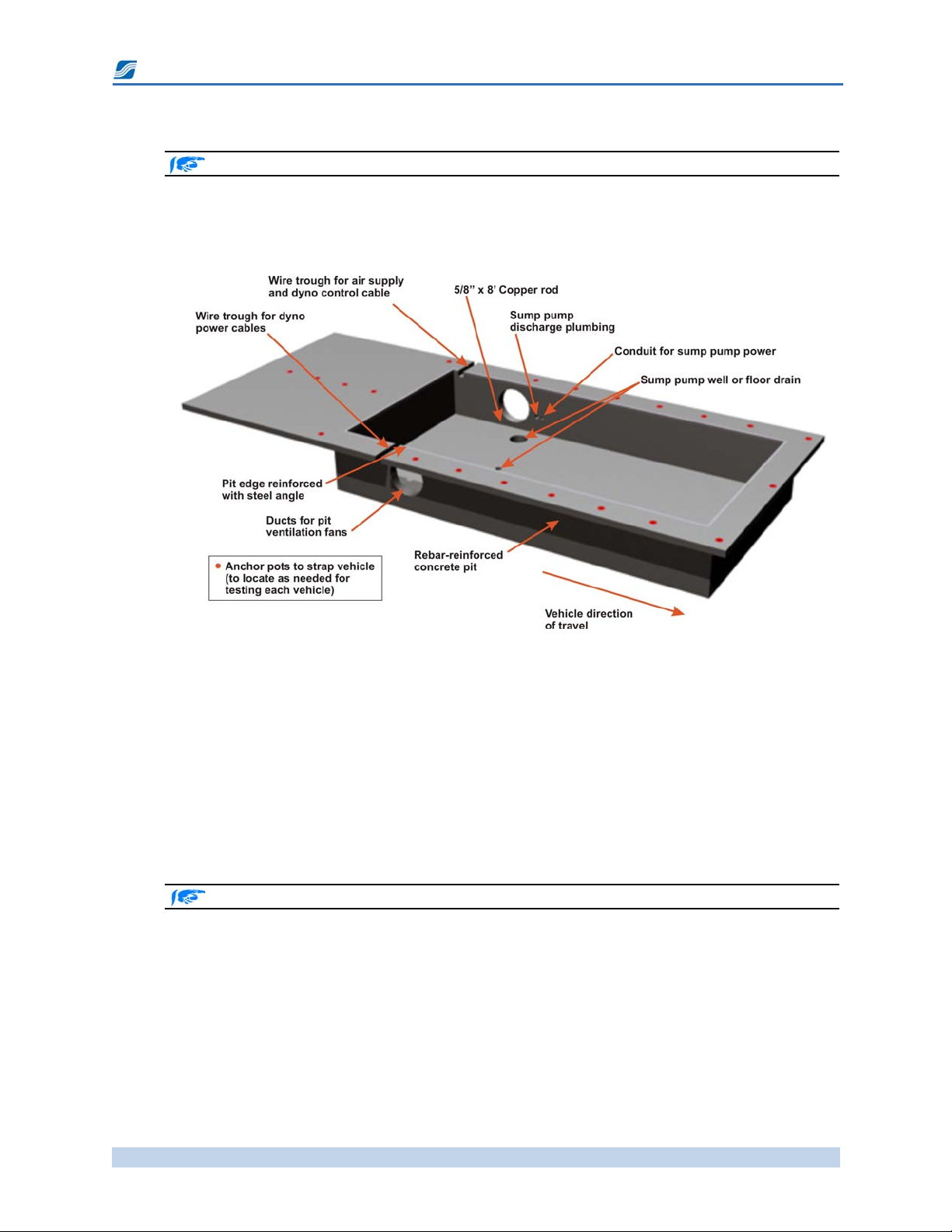
Pit Design
See Figures 3 through 6, “AD-30 AWD Pit Layout” on pages 43 through 46.
The pit for a SuperFlow AD30-AWD chassis dynamometer is constructed on site of poured
concrete with 6” minimum (20 cm) thick walls and steel rebar reenforcement. The concrete should
have a minimum strength of 4000 psi [280 kg/cm2].
Figure 3. Pit Design – Open View
The 24” (60 cm) diameter holes on each side of the pit are for a ventilation system that removes the
heat generated by the air-cooled eddy current power absorbers and any dangerous gases that may
collect in the pit. The ducting for the pit ventilation should extend to the side walls of the test cell
or at least far enough to clear a vehicle mounted on the dynamometer (see “Absorber Cooling and
Pit Ventilation” on page 12).
Embedded in the pit floor are eight weld plates to carry the main weight of the rear rollset.
Additional weld plates are embedded in the pit floor for the front rollset track rail. An angle-iron
weldment is cast in the pit top edges to strengthen the pit edges and support the AutoDyn top
covers.
Weld plate locations are shown on Figure 6, “AD-30 AWD Pit Layout (page 4 of 4),” on page 46.
Install a 5/8” x 8 ft. copper rod through the pit floor into the soil below. The rod is used to ground
the AutoDyn chassis.
Access into the pit for the electrical wiring, compressed air, and sump pump drain is required.
Conduits or a covered trench may be used for the electrical wiring. Typically two electrical cables
will extend into the pit: one for the dynamometer control and the other for the dynamometer
power (see “Electrical Requirements” on page 14).
Floor anchors are required for securing the vehicle on the dynamometer with tie-down straps or
chains (see “Vehicle Restraint Requirements” on page 13). Anchors should be positioned around
the pit to provide multiple tie-points for a wide variety of vehicles.

SuperFlow Product Information
AD-30 AWD Pit Installation 3.30.2020 Page 7
Suggested placement of floor anchors are shown in Figure 5, “AD-30 AWD Pit Layout (page 3 of
4),” on page 45 and Figure 7, “Vehicle Tie-down Points,” on page 47.
Pit Drainage
Water and other fluids can get into the pit from local ground water conditions or spillage from
other sources. If the water level gets too high it can cause damage to the AutoDyn. A sump pump
or floor drain must be provided in the pit floor to automatically remove any accumulated water.
Suggested pumps are shown in “Equipment Recommendations” on page 17.
• A sump pump should be recessed in the pit floor and have a float-actuated switch to
automatically keep the pit empty of any water or other fluids.
• Make sure the electrical wiring conforms to local code requirements for installing an electric
motor in a below-floor-level enclosed area.
IMPORTANT: Many sump pumps come with a standard three-prong plug, so the easy solution is
to put an electrical outlet in the pit; however, because the outlet is in an enclosed pit, this may not
conform to local building codes. Consult a certified electrician to determine the proper installation
of a sump pump in this situation.
• Install check valves or a back flow preventer so water will not drain back into the pit.
• Be sure the pump wiring and plumbing do not interfere with the movement of the front
rollset.
NOTE: Local codes may require water pumped or drained from a dynamometer pit to be routed
through an oil separator or cleaner.
You may also wish to install a drain in the test room floor to help wash down the test cell area.
This drain may also have to be routed through an oil separator.
Ventilation
IMPORTANT: Electric fans, ventilation ducts, and the location of fans in the ducts must conform to
local codes and regulations. Always consult with local authorities when installing a ventilation
system.
Chassis dyno test cells require extensive ventilation systems to address five requirements for safe
and repeatable dyno testing:
• Provide air to the vehicle for combustion
• Remove heat from the test cell
• Cool the vehicle
• Extract exhaust gas and combustion by-products
• Provide pit ventilation and cool the dynamometer eddy current absorber
Although it is best to address these tasks individually, it is possible to combine some systems to
meet two or more of these requirements.
SuperFlow Product Information
AD-30 AWD Pit Installation 3.30.2020 Page 8
Place the master control for the ventilation fans inside the room within easy access for the
dynamometer operator and an emergency cutoff switch outside the room.
See Figure 13, “AutoDyn Room and Pit Airflow (U.S. Units),” on page 53 or Figure 12, “Energy
Balance (Metric Units),” on page 52 for typical AutoDyn airflow requirements.
Suggested fans and other ventilation supplies are shown in “Equipment Recommendations” on
page 17.
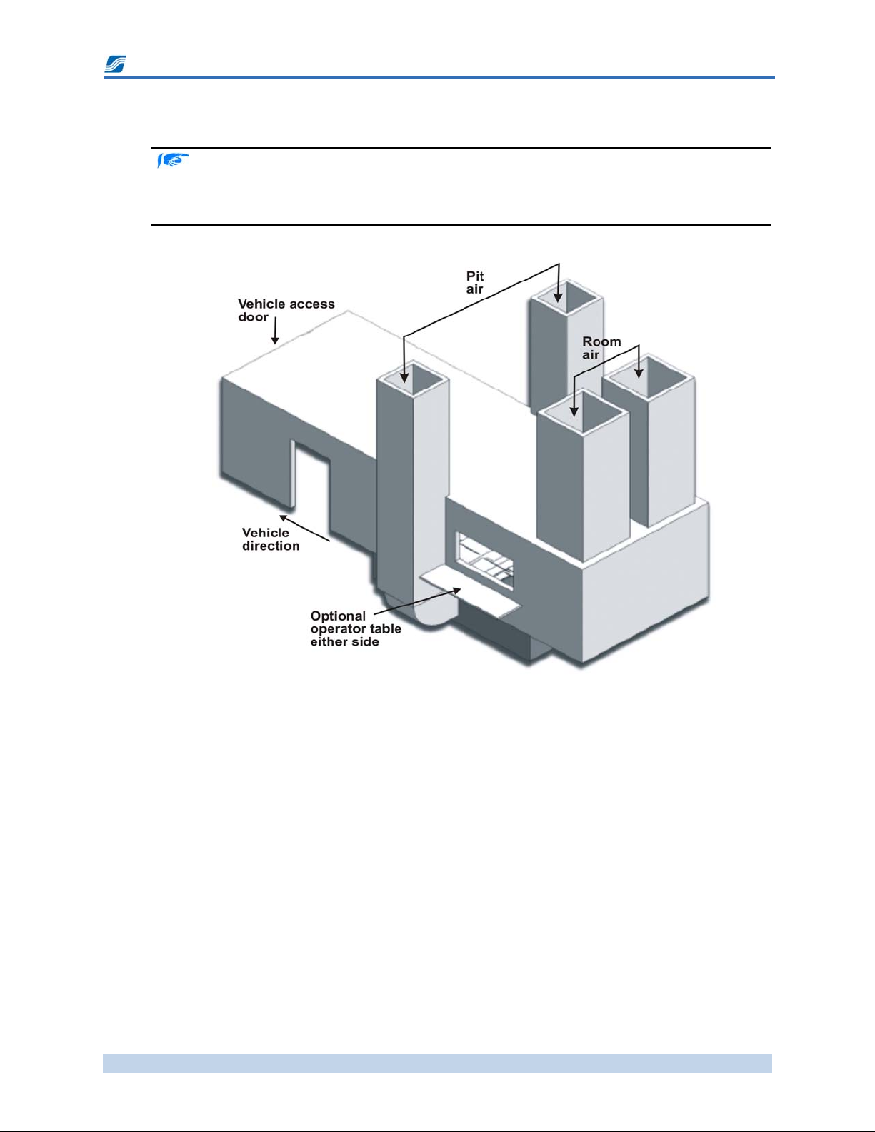
Figure 4. Ventilation Ducts
Combustion Air
Internal combustion engines need clean, cool air to function properly and produce the best
performance. Normally, the engine uses the same air for combustion the air in the dynamometer
test cell, so the airflow in the room must provide combustion air in addition to extracting any toxic
gases and keep the room cool.
If testing the vehicles without filters on the engine, you may be required to filter the air flowing
into the room. If required, filters can be installed on the inlet ducts. SuperFlow recommends 92%
efficient filters and also recommends installing a pressure gauge to measure the pressure drop
across the filter system. When the filters become clogged, the ventilation system may not be able
to overcome the pressure drop, and the airflow though the room will rapidly decrease.
TIP: To improve test result repeatability, use a special duct to direct air from outside the test cell
but inside the building into the engine intake. Drawing air for the engine from inside the
building reduces temperature variations throughout the year. Air for the test cell can then be
brought in from and exhausted to outside the building without filters or conditioning,
substantially reducing heating and cooling expenses.

SuperFlow Product Information
AD-30 AWD Pit Installation 3.30.2020 Page 9
Heat Extraction
Chassis dynamometer testing produces a significant amount of heat that is for the most part
released to the test room air. Ventilation is required to evacuate this heat from the room. If the
room temperature increases during the test or exhaust gas recirculates into the engine inlet, your
test results will vary in an unpredictable manner. Both the quantity and direction of airflow are
critical for repeatable test results.
In chassis dyno testing, about 40% more energy is released into the air than the engine tested in
the vehicle produces. This energy is in the form of heat from the vehicle’s engine and exhaust as
well as heat from the various drivetrain components and their corresponding drivetrain frictional
losses. So for every 100 hp of engine flywheel power, you must assume it releases 140 hp in the
form of heat and then size the ventilation system so it is capable of removing the heat. If your
system is not capable of removing all of this heat effectively, your testing will suffer as a result of
excessive temperatures in the room, or you will be forced to run limited duration tests with a cool-
down period between tests.
Generally, for every 1 hp of engine power produced for 1 minute, the temperature of 2,313 cubic
feet of air in a room (at sea-level standard conditions of 60°F, 0% relative humidity, and 29.92 inHg
barometric pressure) will be heated 1°F.1A room ventilation system must be designed with the
capability to maintain a temperature at the rear of the vehicle that will not exceed the temperature
rating of the extraction system. Without adequate ventilation, on a nice 70°F day the temperature
in your test cell will be intolerable within minutes.
Example:
If the test vehicle is rated at 400 hp (at the flywheel) and you want to limit the temperature increase
in the room to 25°F, you need a ventilation system that flows more than 50,000 cfm.
• 1.4 is 40% increased heat load
• 2313 ft.3 is the volume of air affected by a 1° increase in temperature in 1 minute by 1 hp.
In a 30ft. x 12ft. x 8ft. (2,880 ft.3) test cell, 50,000 cfm is almost 17 air exchanges per minute
(50,000 divided by 2,880).
If a separate exhaust extraction system is in place, room
ventilation airflow can be decreased to a rate equaling 10 to
12 air exchanges per minute. Regardless of the test cell
design, the room ventilation fans should be sized to provide
enough air to the room to prevent an excessive buildup of
heat in the room and remove any dangerous fumes not
captured by the exhaust extraction system.
SuperFlow recommends using tube-axial fans for ventilation
of any closed-room test cells. The air should enter the room
at the front of the vehicle and be directed rearward. Ducting
can be used to direct the air at the radiator level of the
vehicle. Air can exit out the rear door of the room or through
the rear ceiling or rear sidewalls.
Figure 5. Room Ventilation Fan
1. Thermodynamics, J.P. Holman, McGraw-Hill College, 4th edition, ©1988
400hp 1.42313ft3
25F
-------------------------------------------------------------------51811cfm=

SuperFlow Product Information
AD-30 AWD Pit Installation 3.30.2020 Page 10
It is advisable to locate the fans at the rear of the test cell to extract air out of the room and
therefore create a slight negative pressure in the room to help prevent fumes and heat from the
test cell from entering other areas of your building or collecting in the corners. It is also advisable
to locate the fans or use duct work as necessary near floor-level to assist in directing airflow along
the path the vehicle will normally experience on the road.
The large fans required to provide the necessary airflow are noisy, so install them in a location
where the noise causes minimal disturbances for your employees and neighbors. You may need to
take additional protective measures such as enclosing the fans and ducts in sound-dampening
material. Self-closing shutters on the air outlets (and inlets if applicable) are advisable so the duct
openings can be sealed off when the dynamometer is not in use.
Vehicle Cooling
The main room ventilation system should evacuate heat released by the vehicle cooling system,
engine block, transmission, and exhaust. However, in many cases the airflow patterns resulting
from the room ventilation system do not adequately cool certain vehicle components. The engine
compartment and undercarriage exhaust system are usually the most troublesome areas.
Figure 6. Vehicle Cooling
To compensate for this deficiency, SuperFlow recommends spot cooling fans. Although these fans
do not increase the overall airflow through the room, they modify the local patterns and speeds of
the airflow to accomplish specific goals. High-speed fans are commonly used for these tasks.
Some racing vehicles require air speed through the radiator at near road-speed. Achieving high
flows at high speeds requires tremendous power which explains why many high-performance
chassis dyno rooms resemble wind tunnels containing fans of several hundred horsepower.
As an example, to blow air at 100 mph [160 km/h] through a standard size radiator would require a
fan capable of about 50,000 CFM [90,000 m3/hr]. The motor required for a fan of this size could
exceed 50 HP [37 kW]. If your requirements do not quite reach these levels, you should purchase a
set of mobile high-speed fans of 5000–10000 cfm [8500–17000 m3/hr] which can be positioned in
critical areas.
TIP: SuperFlow data acquisition and control systems are capable of supplying a 0–10VDC control
signal based on engine speed to a variable speed fan controller. This allows more realistic
test simulations where the vehicle will experience airflow in near-real-world road conditions.
In some cases you may want to install an under-car ventilation system. These provisions should
be made at the time of installation. Perforated in-floor rails or ducts can be installed below floor
Spot fan High-capacity fan

SuperFlow Product Information
AD-30 AWD Pit Installation 3.30.2020 Page 11
grade. Incorporating a pressure blower in this system helps you more easily control exhaust and
undercarriage temperatures.
Exhaust Extraction
WARNING: A proper exhaust extraction system is critical for the safety of your employees
and customers both inside and outside the test room. If the room ventilation is good, a
separate engine exhaust collection may not be necessary. However, to ensure the safety of
all personnel in your building, exhaust from the vehicle must be completely removed.
Many test cells are built with the idea they will have enough airflow with a room ventilation fan to
extract the exhaust without any help from duct work or auxiliary fans. If the cell is small and the
airflow is many thousands of cfm (exchanging all air in the room at least 12–15 times per minute),
this is possible. However, very few test cells achieve this goal. Sometimes the best solution is to
use hoses or flexible metal with a fan on the other end to suck out the exhaust (see Figure 7).
Consider that for every 100 hp of engine power, roughly 17 pounds of exhaust is produced per
minute which is equivalent to 223 cfm of airflow. In addition to noxious gases, a significant
amount of heat is released through the exhaust system, especially with the engine at wide-open
throttle and at full load. The exhaust system must be able to handle both the flow and temperature
of the exhaust gas. Most ventilation ducts and fans only handle temperatures up to 250 deg F (110
deg C). Therefore, exhaust ducts, hoses, and fans should be rated for high temperatures. The
extraction fan can be rated for a lower temperature if the exhaust is diluted with cooler air prior to
reaching the fan.
IMPORTANT: Hoses typically used in service garages are not applicable for dynamometers as
they are only rated for slightly above idle temperatures.
It is much easier to build a system with higher flow capacity than one that can handle exhaust-
level temperatures. In addition, sealing the exhaust pipe can influence engine performance by
increasing the exhaust back pressure. With a high-flow extraction system, exhaust gas can be
diluted with ambient air to reduce the overall temperature in the exhaust system. Leave some
space between the vehicle exhaust and the duct inlet so the fan pulls room air into the pipe. This
will dilute the exhaust gases by about 2 to 1 and help prevent overheating the fan.
Figure 7. Exhaust Extraction

SuperFlow Product Information
AD-30 AWD Pit Installation 3.30.2020 Page 12
Alternately, connect directly to the exhaust pipes and integrate an air inlet near the pipe entrance
to provide dilution air from inside or outside the test cell. Dilution air can even be introduced
from outside the building. The piping prior to the dilution point must be rated for high
temperatures.
As with spot cooling fans, the exhaust fan is usually a centrifugal type, high-speed fan. Proper
temperature-resistant ducting should be installed to capture the exhaust gas close to the vehicle
tailpipe.
For an exhaust extraction system, SuperFlow recommends selecting a fan capable of flowing 1,500
cfm for every 100 hp of engine power. Ensure that the duct system is capable of providing the
required flow with the fan you plan on using. A system capable of 1,500 cfm per 100 flywheel hp
will provide a 7:1 dilution ratio which should keep the temperature of the diluted air in the ducts
below 250°F. Due to incomplete mixing at the collection point, it may be desirable to use metal
ducting for the first 10 ft. of the collection system.
If relying on the room ventilation to remove the exhaust from the vehicle, you must assume that
for every 100 hp of engine power, roughly 140 hp releases as heat into the room. Therefore, the
specifications for a ventilation system to handle both room ventilation and exhaust extraction
should be increased by 40% over the standard requirements.
For more information on exhaust extraction and system design suggestions, contact SuperFlow
Sales or Customer Service and ask for the document “Chassis Dyno Exhaust Extraction” PDF.
Absorber Cooling and Pit Ventilation
Pit ventilation is required for two reasons: to remove heat generated by the absorbers and to
evacuate potential explosive gases.
The eddy current Power Absorption Unit (PAU or absorber) in the pit absorbs power generated
by the vehicle and converts it to heat. Most tests on the AutoDyn are short and limited first by the
vehicle overheating when testing at full power and second by the eddy current absorber
overheating. Consequently, tests can be run for a longer period at much higher power levels if the
vehicle and absorber are kept cool. The vehicle temperature is maintained by the room air
ventilation whereas the absorber temperature is handled by a pit ventilation system.
The heat from the absorber is removed by supplying fresh air to the pit during vehicle operation.
SuperFlow recommends two tube-axial fans for pit ventilation: one fan pushes the air into the pit,
and one fan extracts air from the pit. One fan alone does not normally have enough pressure
capability to overcome the duct flow losses. These fans can be mounted on the roof, an outside
wall, or anywhere within the ducts. It is best to install the exhaust fan at the end of the duct to
ensure all air (possibly contaminated) is exhausted from the building. SuperFlow recommends a
pit ventilation system capable of flowing 1,500 cfm per 100 hp of engine power of vehicle to test.
This limits the temperature rise in the dyno pit to 80°F. A system with less flow than this will limit
the length of the tests being performed and requires a cool-down period between tests.
For efficiency, airflow should be directed across the absorbers. Therefore, the ventilation ducts
should be placed on opposite sides of the pit and in line with the absorber which is about four feet
from the back wall of the pit.
• Ducts may be round or rectangular as long as the cross-sectional area is sufficient to manage
the airflow.
• Make sure the fans and duct system are compatible in providing the required airflow.
• The pit ventilation ducting should extend to the side walls of the test cell or at least far
enough to clear a vehicle mounted on the dynamometer.
• If the fan motors are actually located in the pit, they should be rated as explosion-proof.

SuperFlow Product Information
AD-30 AWD Pit Installation 3.30.2020 Page 13
• Place the master control for the ventilation fans inside the room within easy access for the
dynamometer operator and an emergency cutoff switch outside the room.
Figure 8. AD30-AWD Pit Ventilation
An option is to replace the pit covers on one side of the absorbers and closest to the pit edge with
metal grates so air is drawn from the test room into the pit and out the exit ducts. One fan may
suffice with this design. If replacing solid metal covers with grates, make sure the grating is
supported sufficiently to support the weight of a vehicle that may possibly drive over the grating.
NOTE: The fans must deliver the required flow against a pressure of at least 1.25” (3 cm) of water
pressure to overcome the duct flow losses. The fans listed in “Equipment Recommendations” on page
17 here meet that requirement. Do not try to substitute a lower velocity fan design.
TIP: Placing the AutoDyn next to an external wall makes it easier to route ventilation ducts
outside the building.
Vehicle Restraint Requirements
Vehicles must be carefully and securely restrained when testing on a dynamometer, more so on an
all-wheel-drive dynamometer. Because the vehicle is sitting on free-turning rolls, the only
restraint comes from straps securing the vehicle to the test cell floor. Three or four restraining
straps are required at each end of the vehicle. In some applications, straps are needed along the
sides of the vehicle. Front-wheel-drive vehicles are particularly susceptible to sideways movement
because the testing primary load is on the steering axle.

SuperFlow Product Information
AD-30 AWD Pit Installation 3.30.2020 Page 14
Figure 9. Vehicle Restraint – AWD
The straps are attached to the floor with flush-mounted floor anchors. Floor anchors can be
integrated in the room floor when the concrete is poured or special anchor pods are inserted into
holes bored into the concrete floor and wedged in place. Chains or load hooks can be attached to
the anchor points.
Figure 10. Tie-down Anchor and Straps
Use adjustable-length, ratcheting restraining straps with at least a 5000-lb. (2200-kg) load-working
capacity. Straps with ends terminated in J-hooks or eye loops are the most useful. You will need at
least four side straps, each at least 8 ft. (2.5 m) long and four front/rear straps, each at least 12 ft.
(3.5 m) long.
SuperFlow recommends installing at least 12 tie-down points as shown in Figure 7, “Vehicle Tie-
down Points,” on page 47. If you are testing specialty vehicles, you may want to add more tie-
down points. At least three points must be used at each end during testing. Add wall-mounted
hooks for storage when the straps are not in use.
NOTE: If using the anchor pods purchased from SuperFlow (part number 3420P-1300), install them
with the long slot pointed toward the vehicle.
Electrical Requirements
WARNING: All electrical installations must adhere to your local codes and regulations.
SuperFlow cannot advise as to the proper installation of electrical devices and wiring for
your area. The recommendations in this section are suggestions only. Consult a local,
certified electrical contractor for assistance with lighting and electrical installation.
Floor anchor pod
Ratchet strap
Axle strap Sling strap

SuperFlow Product Information
AD-30 AWD Pit Installation 3.30.2020 Page 15
Dynamometer Chassis
The AutoDyn power absorber requires 25 amps of 208 to 240 VAC power wired from a power
distribution box through a 1” (25 mm) diameter conduit in the pit or a trench cut in the side wall to
the rollset power junction box on the AutoDyn. The junction box is located on the front side of the
rear rollset just to the right (looking forward) of the eddy current absorber (see Figure 32,
“Electrical Controls,” on page 35).
This power operates the eddy current absorbers and the hydraulic pump that moves the front
rollset. Both devices can be run on the same circuit because both should never be on at same time.
In addition to the power cable, a control cable is routed from the AutoDyn through a trench or
conduit to the SuperFlow Data Acquisition System (sensor box). The connection for this cable is an
interconnect panel on the left side (looking forward) of the rear rollset.
If the conduit or trench is placed about one foot from the rear wall and about one foot below the
top edge of the pit, it will be very close to being in line with the interconnect panel. Otherwise,
place it no closer than 4 feet [1.2 meters] or farther than 8 feet [2.4 m] from the rear wall. This will
put the cable and air hose between the rollset frames making access much easier. Conduit should
be no less than 18” [45 cm] from the pit floor.
• A 3” [75 mm] conduit is required for the control cable and air line for easy passage of the
large connector on the control cable.
• The power cable and the control cable should not be routed together in the same conduit or
trench.
•A a master disconnect switch for the VAC power should be within sight of the rollset.
• Do not combine the dynamometer power with any other devices such as fans or pumps.
Data Acquisition System
The AutoDyn sensor box, computer, and printer requires a 110 VAC, 15-amp or 240 VAC, 8-amp
supply using approved GFI plug receptacles. SuperFlow recommends using an Uninterruptible
Power Source (UPS) or a good surge suppressor for these devices.
Miscellaneous
Additional power is required for the fans, sump pump, room lights, and any power tools or
devices that may be used in the room.
• Use only Ground Fault Interrupter (GFI)-protected power outlets in the test cell.
• Install two-way switches inside and outside the test room for the lights.
• Place the master control for the ventilation fans inside the room within easy access for the
dynamometer operator and an emergency cutoff switch outside the room.
Air Requirements
Compressed air at 100 psi (600 kPa), must be supplied to the AutoDyn to operate the AutoDyn roll
lock. This line is routed into the pit through a conduit or a trench cut in the side wall of the pit
edge. The connection is on the left rear side (looking forward) of the rear rollset chassis next to the
control cable panel. The air line can be routed alongside the AutoDyn control cable or the power
cable.
• Provide an easily accessible air shutoff valve.
• Install a regulator, filter, and water trap where they can be easily monitored.

SuperFlow Product Information
AD-30 AWD Pit Installation 3.30.2020 Page 16
• In situations where high concentrations of water may be in the air supply, install an
automatic water drain in the pit at the lowest level of the air supply line.
Suggested air supply equipment is shown in “Equipment Recommendations” on page 17.
Static Electricity
An ungrounded vehicle on a chassis dynamometer will create a very high static charge as the tires
turn. This charge normally dissipates fairly quickly after the vehicle is stopped if an alternative
ground path is not provided.
However, the alternative ground path can be the handheld controller (wired model) or the
operator while stepping out of the vehicle. The back plate of the handheld is metal and is
connected to earth ground through the sensor box. If the handheld backing plate is laid on a metal
part of the vehicle or the operator is in contact with the backing plate and touches a metal part of
the vehicle, a static discharge can occur. A discharge can also occur when the operator steps down
from the vehicle and contacts the ground. Such a discharge can cause severe damage to the system
electronics or give the operator a mild electric shock.
The best way to prevent any static buildup and subsequent discharge is to provide a positive
ground path. The easiest and most efficient method is to connect a ground strap from the vehicle
frame to a positive earth ground. This strap can be flat metal braid, welding cable, battery jumper
cables, or a length a thick, solid copper wire. With one end permanently attached to an earth
ground point and a alligator-style clip on the other, it only takes a few seconds to ground the
vehicle and prevent damage or injury.
The AutoDyn pit design has a copper grounding rod through the pit floor. A wire or strap is
connected from the AutoDyn frame to this rod. Therefore, a vehicle ground strap can be attached
to the AutoDyn frame that will provide a discharge path for static electricity.
Convenience Issues
Based on experience gathered while installing and visiting countless test facilities, SuperFlow
suggests making these enhancements to your facility:
• Wide-angle mirrors positioned in front of the driver so all parts of the test room are visible
during tests.
• A video computer monitor or projector to display WinDyn data screens on the front wall
during the tests.
• Wireless two-way communication link between driver and system/computer operator or
an intercom between the test room and the control room.
• Digital camera for pictures of the vehicle while tested. The pictures can be downloaded to
the test system computer to display and store with the test data files. Additionally, pictures
provide a quick method to record the vehicle configuration and cooling blower
arrangement for the test, improving test repeatability.
• A microphone in the test room and driving speakers in the control room (and customer
viewing room). Because of the test room’s noise insulation, it may be difficult to hear
abnormal engine or drive line sounds from the control room.
• A telephone line for communication. A wireless telephone is convenient. When requesting
assistance from SuperFlow Customer Service, the dynamometer operator must be near the
system.
Table of contents


