3. SPECIFICATION
Model no: .................................................................. VS0208
Maximum pressure:.........................................................2bar
Supply:............................................................................. 12v
Cable length:................................................................2.5mtr
Hose length:.................................................................2.9mtr
Capacity:........................................................................... 5ltr
Weight:.......................................................................... 6.2kg
4. OPERATION
WARNING!Familiariseyourselfwiththehazardsofbrakeuid-readthemanufacturer’sinstructionsonthecontainer.
4.1. Preparing unit for use.
4.1.1. Before using on a vehicle for the first time, it is necessary to bleed all air out of the unit’s system.
4.1.2. Half fill the unit’s reservoir with fluid of the required specification, but do not replace the filler cap, connect the power cable to a suitable
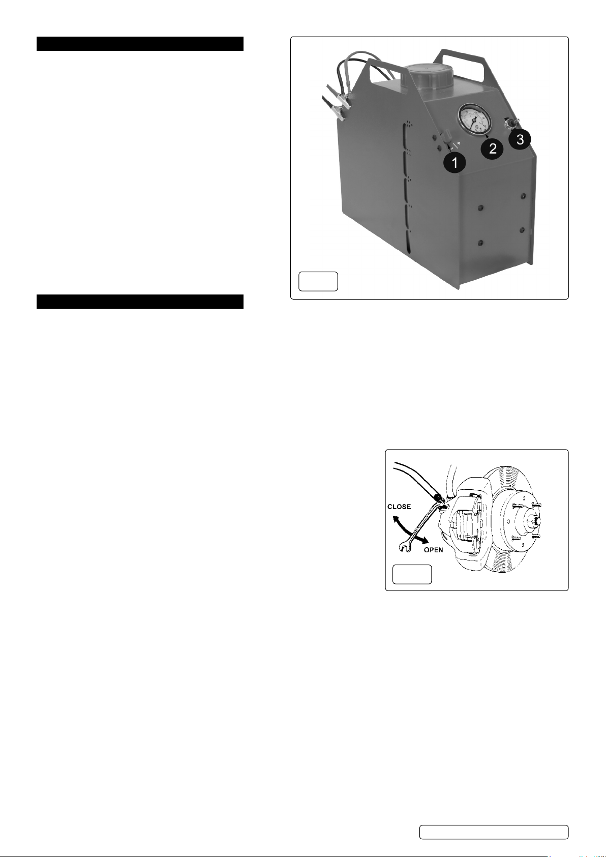
battery,ensuringthatthepowerswitch(fig.1.3)isinthe“off”positionandthepressureswitch(fig.1.1)isatthe“-”position.
4.1.3. Attach the black universal adapter to the pressure delivery hose’s quick-fit coupling at the end of the bleed pipe. Hold the cap over the
open neck of the unit reservoir so that fluid will be expelled from the universal adapter into the reservoir.
4.1.4. Turntheunittothe“on”positionattheswitch(fig.1.3),asbrakefluidisdrawnthroughtheunit,airwillbeexpelledfromthesystem.
4.1.5. Increase the pressure by turning the pressureknob(fig.1.1)halfwaybetweenthe“-”and“+”positions.When fluid without any air bubbles
present flows from the delivery hose, turn the unit off.
4.1.6. Remove the universal adapter from the open top of the unit reservoir and replace the filler cap. Further bleeding will not be required
unless the bleed pipe is disconnected from the hose’s quick fit coupling. The unit is now ready to use.
4.2. Brake bleeding procedure.
8DO NOT touch the vehicle’s brake pedal whilst bleeding the brakes.
4.2.1. Refer to the vehicle manufacturer’s instructions for brake bleeding and wheel
sequence before proceeding. If no specific instructions from the vehicle manufacturer
exist, follow the instructions detailed below. If the manufacturer has not supplied a
specific figure for the maximum pressure for this operation, it is advised to keep the
pressurewithinthe1.5to2Barrange,toavoiddamagingthebrakefluidreservoiretc.
4.2.2. Fully prepare the vehicle by jacking it up or by using a ramp, remove the wheels from
the vehicle as required to gain access, so that work can commence as soon as the
unit is turned on.
4.2.3. Remove the cap on the vehicle’s brake fluid reservoir. If the brake fluid level is not
at its maximum level, top it up, ensuring that there is some air space above the fluid.
4.2.4. Fit the universal adaptor to the brake fluid reservoir, tighten it and ensure that there is
a good seal.
4.2.5. Connect the pressure delivery hose’s quick connector to the universal adaptor.
4.2.6. Rotatethepressurevalve(fig.1.1)ontheunittothe“-”position(clockwise)andswitchontheunit.Adjustthepressurebyrotatingthe
pressurevalvetothe“+”position(anti-clockwise)totherequiredpressureonthegauge(fig.1.2),notexceeding2Bar.Thepumpwillstop
automatically when the required pressure is reached. If the slight pulsing of the pump is not required or a lower pressure is desired, turn
thepressurevalveslightlytowardsthe“-”position.
4.2.7. Starting with the wheel furthest away from the brake fluid reservoir, connect one end of a tube from a bleed bottle to the brake
nipple and, using a brake spanner, open the nipple approximately ¼ turn (fig.2), brake fluid will flow through the clear pipe into the
bottle, when there are no visible bubbles in the fluid, tighten the bleed nipple and remove the pipe, taking care not to spill any brake fluid.
4.2.8. Repeat the procedure at each location in turn, as required.
4.2.9. When finished, check all bleed nipples are closed and turn the unit off. Slowly vent the pressure by rotating the pressure valve (fig.1.1)
tothe“-”positionuntilthecorrectleveloffluidisreachedinthevehiclereservoir.Whenthecorrectfluidlevelisachieved,
disconnect the quick fit coupling connector from the universal adapter.
4.2.10. Remove the universal adapter from the vehicle reservoir, taking care not to spill any brake fluid. Disconnect the battery leads.
4.2.11. Check the fluid level and refit the vehicle’s brake fluid reservoir cap.
4.3. Changing the brake fluid.
4.3.1. Carryoutthebrakebleedingprocedureasdescribedin4.2.
4.3.2. Allow a longer period of time when bleeding, to allow the new fluid to flush out the old fluid.
When new fluid can be seen in the clear tube, tighten the brake nipple.
4.3.3. Repeat this procedure at each wheel in turn.
4.3.4. Disconnectasabove(4.2.9.to4.2.11.).
fig.1
fig.2
Original Language Version
© Jack Sealey Limited VS0208|Issue:3(2,3)12/10/18


