Powerex • 150 Production Drive • Harrison, OH 45030 • USA
P 1.888.769.7979 • F 513.367.3125 • www.powerexinc.com
IN599500AV • 20 October 2020
Page 4 of 20
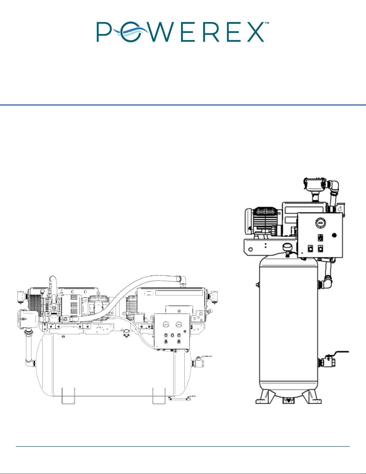
Industrial Vacuum Tankmount Systems
Operating & Maintenance Manual
Description
Powerex vacuum tank mount simplex/duplex units
are designed to provide vacuum for process, molding,
packaging, printing and other similar facilities. Vacuum
tank mount systems can be used for a variety of
air or inert gas. Some water vapor may be contained in
No liquid must reach the vacuum system. The system
be separated and collected upstream of the Powerex
system and disposed of as needed. The exhaust stream
of the vacuum pump will contain the process gas and
may contain some trace oil from the pump operation.
the room can be ventilated if suitable.
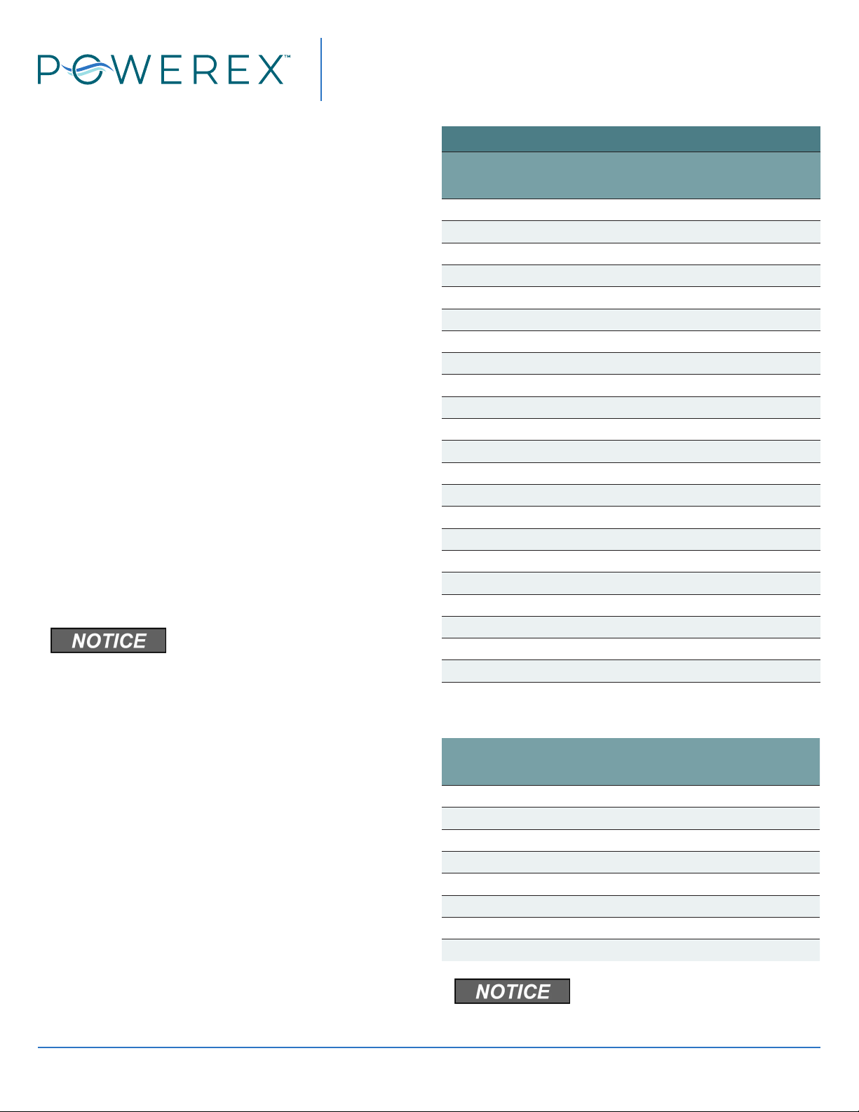
Specications
Product IBVS/IBVD
Operating Voltages 208V, 230V, 460V
Control Panel
Motor TEFC Electric Motor
Tank ASME Rated for 200 psi MAWP/
Full Vacuum
Drive Direct
Inlet and Exhaust
Vacuum Connections
1.5 HP to 4.6 HP – 1 1/4 inch
5 HP to 10 HP – 2 inch
Safety Guidelines
This manual contains information that is very
important to know and understand. This information
is provided for SAFETY and to PREVENT EQUIPMENT
the following symbols..
Danger indicates an imminently
Warning indicates a potentially
Caution indicates a potentially
Notice indicates important
information, that if not followed,
may cause damage to equipment.
NOTE: Note indicates information that requires
special attention.
Components
Vacuum Tankmount Systems
The IBVS and IBVD (Vacuum Tankmount Simplex
and Duplex) systems consist of one or two rotary vane
vacuum pumps that can be operated independently or
in tandem. The system will operate the pump or pumps
to maintain the vacuum level determined by the control
panel settings. The duplex systems control panel
automatically sequences the pumps to maintain equal
run time on each pump. The direct drive vacuum pump
is equipped with a continuous duty TEFC induction
motor. Maintenance on the rotary vane pump is
the pumps.
The pump or pumps draw air through a 10 micron
protection against leakage. A stainless steel protective
equipment on the pumps. The inlet screen protects the
pump from large particles entering the rotor/vane area.
The pumps have a built in gas ballast valve to help
prevent moisture accumulation.
Receiver Tank
The receiver tank is an ASME registered pressure
vessel rated for 200psig maximum allowable working
pressure and suitable for full vacuum. It is installed in
is not intended to be a liquid collector, and failure to
or IBVD system may damage the pumps and void
warranty. A vacuum gauge is installed and a manual
tank drain valve is included.
Factory installed receiver is used for
vacuum capacity only and is NOT a
collection receiver.
Never drill holes in, or perform any
welding on tanks or use them
beyond the rated pressure settings.