Powermate ALUMINUM L Series User manual

PN 011900 Rev.J
PN 310570 Rev.J
Eng. 12/ 09/ 20
For Serial Numbers 43600 and higher.
T20-010.14

Section 1 - General
Warning Page............................................................................
PowerMate Description.............................................................
Delivery and Warranty Registration..........................................
Operator Training Guideline......................................................
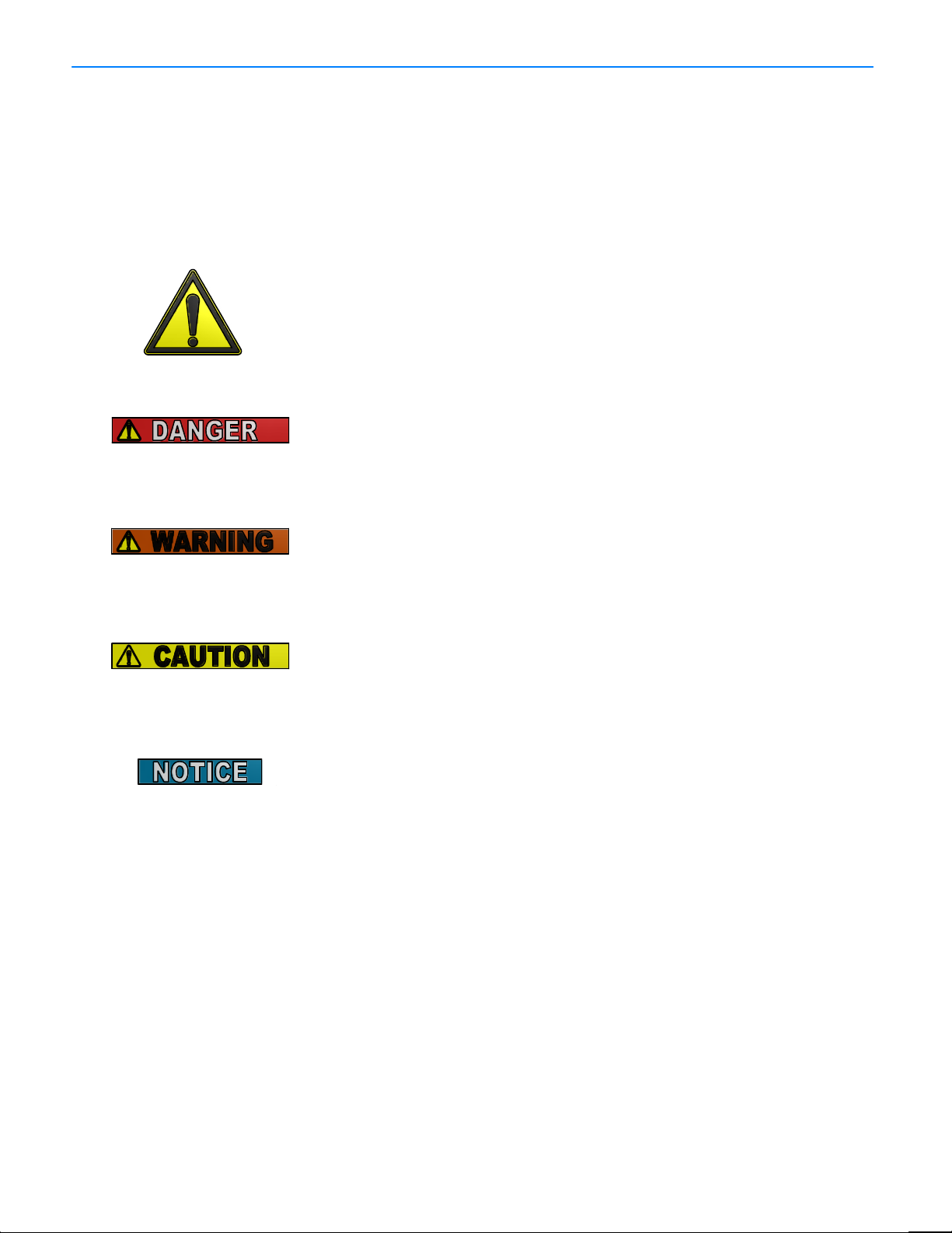
Section 2 - Safety
Hazard Graphical Symbols........................................................
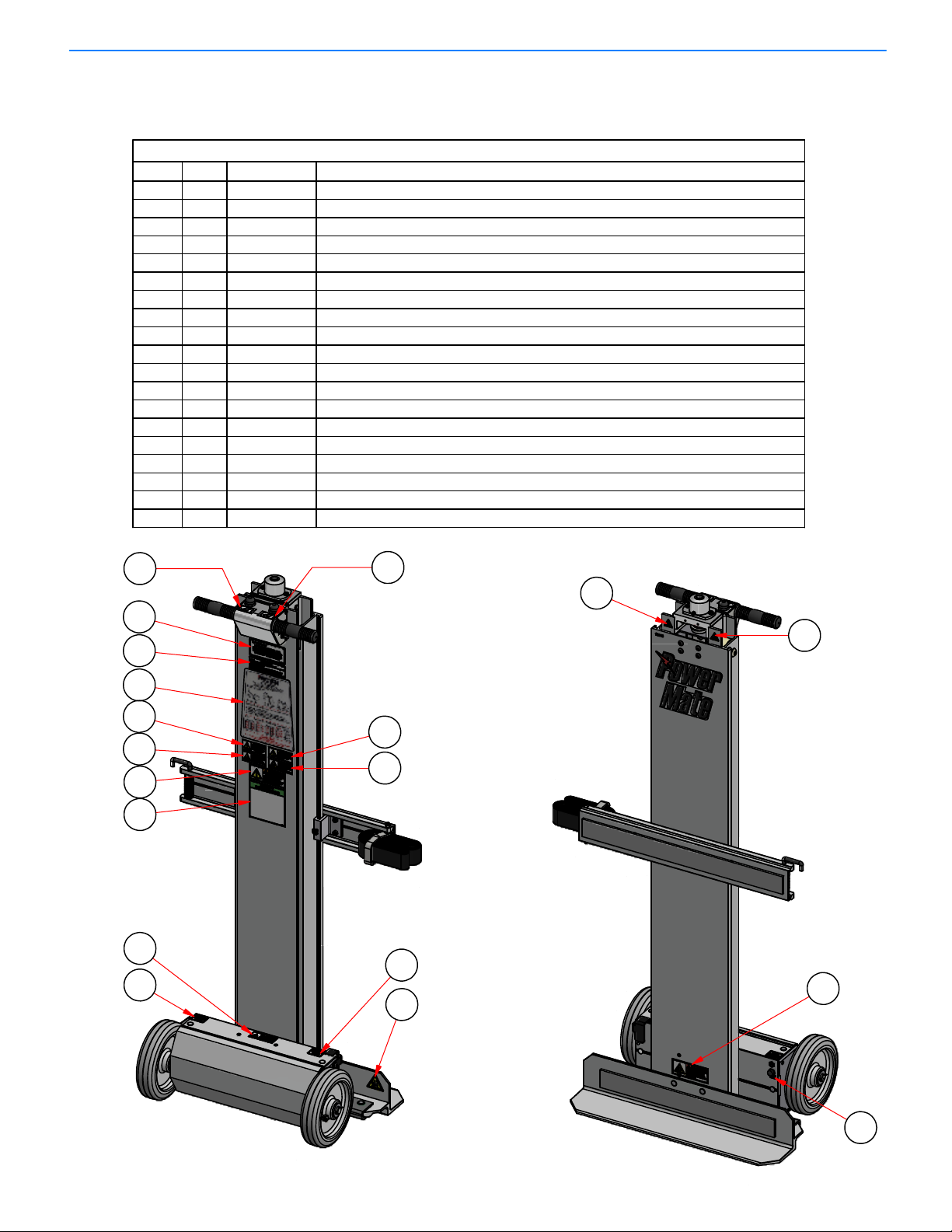
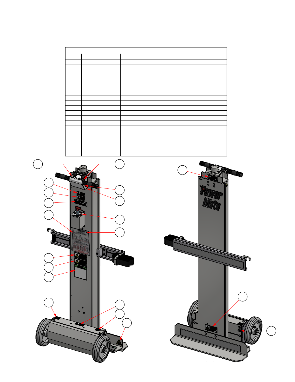
Mandatory Safety Decal Placement...........................................
Safety Precautions....................................................................
Safety Inspection......................................................................
Environment Safety.....................................................................
Loading Safety..........................................................................
Safety in Motion........................................................................
Battery Safety...........................................................................
Battery Charging Safety...........................................................
Section 3 - Instructions
L-Series PowerMate Charging Instruction..............................
Loading Instruction...................................................................
Vehicle Loading.......................................................................
Stairclimbing.............................................................................
Storage Procedure and Battery Care......................................
Section 4 - L-Series PowerMate Component Identification
Model L-1 Exploded View.........................................................
Screw Assembly L-1................................................................
Screw Assembly L-2................................................................
Brake Assembly Kit..................................................................
Bearing Override Kit.................................................................
Section 5 - Maintenance
Maintenance After Every Year of Operation.............................
Procedure for Repairing Drive Screw Assembly......................
Ballnut Removal and Replacement........................................
Installation of Sealed Batteries..............................................
Bottom Rubber Guard Replacement........................................
Push Button Switch Replacement............................................
Strapbar Assembly for L-Series..............................................
Replacement Strap Installation.................................................
L-Series Wiring Diagrams........................................................
L-Series Motor Replacement Instruction………………………
Section 6 - Specifications
L-Series Specifications............................................................
Solidstate Controller.................................................................
Battery Specifications...............................................................
Section 7 - Accessory Installations
Battery Charger Remote Installation.........................................
PowerMate RT Cart Attachment Instruction...........................
Section 8 - Accessories
Accessories..............................................................................
Warranty...................................................................................
Declaration of Conformity.........................................................
Daily Maintenance Schedule....................................................
PowerMate
®
Operation Manual
TABLE OF CONTENTS
1.01
1.02
1.02
1.03
2.01
2.02
2.04
2.05
2.05
2.06
2.06
2.07
2.08
3.01
3.02
3.03
3.04
3.05
4.01
4.03
4.04
4.05
4.06
5.01
5.03
5.04
5.05
5.06
5.07
5.08
5.08
5.09
5.11
6.01
6.02
6.03
7.01
7.02
8.01
8.03
8.04
8.05
PN 011020 Rev. F
Eng. 11/ 16/ 15
i

PowerMate
®
Operation Manua
l
W
ARNING
Training courses are available through
L P INTERNATIONAL INC., please call
1-800-697-6283
Failure to obey the Instructions and Safety
rules in this manual could result in death or
serious injury.
Read the Operating Manual completely.
Only competent, trained operators may use
this equipment.
Training is essential to understanding all
the features and capabilities of your
PowerMate, and ensure good safe work
practices.
PN 011100 Rev.E
Eng. 04/ 25/ 14
1.01

PowerMate
®
Operation Manual
PowerMate
®
MODEL L-SERIES
The PowerMate
®
L-Series Models are motorized electric hand trucks used
for the safe movement of heavy and awkward loads. It can move loads up and
down stairs, on and off of vehicles or loading docks and across flat surfaces.
The design takes advantage of the principle of leverage. All of the lifting of
the load is performed by the equipment.
The PowerMate®L-Series units are designed specifically to move loads with
various center of gravity locations. Refer to the Load Recommendation Chart for
capacities.
DELIVERY AND WARRANTY REGISTRATION
When your PowerMate
®
Motorized Stairclimber is delivered, unpack and
inspect the unit for damage or shortage of parts. If required, make note of any
deficiencies on the Delivery Acceptance Form. Registering your unit for the
Warranty can be done online at www.powermate.info. Click on Service, fill in the
required fields under Warranty and click Send Now.
Standard Equipment
One Strapbar
Battery Charger
Optional Equipment
Wheel Brakes
Step Extension
Cylinder Attachment
Hot Water Tank Attachment
Extended Depth or Width Toe Plate
Refer to the accessory page for details.
The use of this equipment with any options other than those
specified in this manual may create a hazard.
Manufactured By:
L P INTERNATIONAL INC.
P.O. Box 696, 151 Savannah Oaks Drive
Brantford, Ontario, Canada N3T 5P9
TEL: (519) 759-3292 FAX: (519) 759-3298
1-800-697-6283
1.02 PN 011910 Rev.E
Eng. 04/ 25/ 14

PowerMate
®
Operation Manual
OPERATOR TRAINING
The PowerMate
®
L-Series Model has been tested and inspected by both the
manufacturer and the distributor to ensure the quality of manufacture and
operation. The equipment is delivered by the distributor, fully assembled and
ready for use.
The PowerMate®L-Series Model is unique in its operation and is used to move
heavy and awkward loads. For these reasons, classroom and hands-on training
in safe and efficient operating procedures for all operators is absolutely
necessary.
During the training, the operator should
LEARN HOW TO DO THE FOLLOWING:
General Use the Load Recommendation Instructions
Follow the General Safety Rules
Strapbars Adjust the location of the strapbars.
Adjust, tighten and release the straps.
Stow loose strapping when not in use.
Flat Surface Raise the wheels to incline the load back.
Reposition the load in balance over the wheels.
Move over obstacles on the floor.
Bring the load back to an upright position.
Stairclimbing Position the wheels and heelplate on a stair.
Climb up and down stairs.
Rest safely in a balanced position on stairs.
Pivot on tight landings.
Lifting Load and unload onto vehicles or loading docks.
Load and unload small vans.
Two Operators Work as a team with another operator.
PN 011190 Rev.E
Eng. 04/ 25/ 14
1.03

The PowerMate
®
products use graphical symbols, safety colours, and signal words
throughout the Operators Manual and on the units themselves. Operators using the
PowerMate®must familiarize themselves with these symbols.
NOTICE: The signal word to address practices not
related to personal injury.
CAUTION: Indicates a potentially hazardous situation
which, if not avoided, may result in minor
or moderate injury.
WARNING: Indicates a potentially hazardous situation
which, if not avoided, could result in death
or serious injury.
DANGER: Indicates an imminently hazardous situation
which, if not avoided, will result in death or
serious injury.
Safety Alert Symbol: This symbol indicates a potential personal
injury hazard. Safety information following
this symbol must be followed to avoid
possible injury or death.
HAZARD GRAPHICAL SYMBOLS
SAFETY LABEL MAINTENANCE
Safety of the operator and surrounding environment must be considered at all times.
To that end, safety labelling on the PowerMate®must be maintained to provide legible
safety information. Clean the labels with soap and water. Do not use solvent-based
cleaners because they may damage the labels. Replace damaged or missing labels.
Replacement labels may be purchased from L P International Inc. Customer Service
Phone number 1-800-697-Mate.
PowerMate
®
Operation Manua
l
2.01 PN 011090 Rev.E
Eng. 04/ 25/ 14

PowerMate
®
Operation Manual
MANDATORY SAFETY LABEL PLACEMENT
Standard L-1/L-2 PowerMate®Units
NOTE: Model L-1 shown.
PARTS LIST
DESCRIPTIONPART No.QTYITEM
DECAL LS DISTRIBUTED BY LP055840C11
DECAL LS MAINTENANCE L-1/L-2055870/8012
DECAL LS LOAD DOWN/UP055830A13
DECAL LS ON/OFF
055850A14
DECAL LS CHARGER PLUG055820C
15
CAUTION DECAL - AUTHORIZED PERSONNEL
057010A16
DANGER DECAL - EXPLOSIVE ENVIRONMENT
057040A17
DANGER DECAL - CRUSH HAZARD FOOT
057020A18
DANGER DECAL - ELECTRICAL SHOCK
057030A19
WARNING DECAL - ROTATING SHAFT PICTOGRAM
057100A110
WARNING DECAL - CRUSH HAZARD FOOT PICTOGRAM
057140A211
WARNING DECAL - KEEP OFF
057050A112
WARNING DECAL - PINCH POINT HAZARD
057090A113
WARNING DECAL- ROTATING SHAFT/HAIR Small
057120A114
WARNING DECAL - ROTATING SHAFT/HAIR PICTOGRAM
057130A115
DECAL - SAFETY INSTRUCTION LS
057190A116
DECAL - FAULT ALERTS057160A117
DECAL - FUSE 10 AMPS057170A118
DECAL - CIRCUIT BREAKER PRESS OFF057150A119
PN 011030 Rev.G
Eng. 12/ 07/ 20
2.02
Load Down Load Up
1
17
2
12
7
14
6
13
16
9
5
11
19
15
10
18
8
33

PowerMate
®
Operation Manual
MANDATORY SAFETY DECAL PLACEMENT Fo
r
L-1/L-2 PowerMate®Units With Battery Switch
NOTE: Model L-1 shown.
PARTS LIST
DESCRIPTION
PART No.
QTY
ITEM
DECAL LS ON/OFF055850A11
DECAL LS CHARGER PLUG055820C
12
DECAL LS MAINTENANCE L-1/L-2055870/8013
DECAL LS LOAD DOWN/UP
055830A14
DANGER DECAL - EXPLOSIVE ENVIRONMENT057040A1
5
DANGER DECAL - CRUSH HAZARD FOOT
057020A16
DANGER DECAL - ELECTRICAL SHOCK057030A1
7
WARNING DECAL - CRUSH HAZARD FOOT PICTO
057140A28
WARNING DECAL - KEEP OFF057050A19
WARNING DECAL - MOVING PARTS Large
057060A110
WARNING DECAL - PINCH POINT HAZARD
057090A111
WARNING DECAL - SCREW GUARD
057070A112
DECAL - SAFETY INSTRUCTION LS
057190A113
DECAL - FAULT ALERTS
057160A114
DECAL - CE MARK APPROVAL
055860A115
DECAL - DATE OF MANUFACTURE057210A116
DECAL - FUSE 10 AMPS
057170A117
DECAL - ROTARY SWITCH057180A118
DECAL - CIRCUIT BREAKER PRESS OFF
057150A119
2.03 PN 011040 Rev.F
Eng. 01/ 25/ 19
Load Down Load Up
4 4
2
5
9
14
3
15
18
16
1
10
11
13
7
19
8
6
17
12

PowerMate
®
Operation Manua
l
SAFETY PRECAUTIONS
READ THE MANUAL (Mandatory)
Read all safety and operating instructions before anyone operates your
PowerMate®Unit. Use the PowerMate®unit only as described in this manual.
Retain all safety and operating instructions for future reference. Ensure they are
readily available.
Heed all warnings in the safety and operating instructions.
Follow all installation, operation, service, and safety instructions.
Operator must have received approved training on the PowerMate®unit to be
used. Training shall include theory, practice, and testing.
Never allow unqualified or un-authorized personnel to operate the equipment.
Operator must be familiar with normal operating practices and procedures.
Whenever there is and doubt as to safety, the operator should stop the operation
and not proceed until safe conditions are restored.
Operator is responsible for maintaining proficiency on PowerMate®equipment.
Familiarity with instructions, safety procedures, maintenance practices, controls,
operation, loading, are required at all times.
WARNING: Only trained personnel shall operate PowerMate®equipment. Failure
to comply may result in possible severe injury to the operator and/or others, and
damage and/or loss of property.
Wear safety shoes. Keep hair, loose clothing, fingers and all parts of the body
away from pinch points and moving/rotating parts. Use equipment handles and
controls for manoeuvring and operation.
Operator must have good hearing and vision (with or without correction) and
must have good depth perception.
Operator must not be afflicted with any health condition(s) that might cause loss
of control or ability.
Do not operate the equipment when using alcohol or taking medication that will
affect your physical performance or judgement.
Do not eat or drink during the operation of PowerMate®equipment.
Stay alert when operating PowerMate®equipment.
No horseplay or practical jokes when operating the equipment.
Do not lift people and never ride on the PowerMate®Unit.
Do not abuse the equipment. Use PowerMate®equipment only for their
intended use.
2.04 PN 011110 Rev.E
Eng. 04 / 25/ 14

SAFETY INSPECTION
ENVIRONMENT SAFETY
WARNING: Do not use PowerMate
®
equipment if it is damaged. Check for corrosion.
Failure to do so may result in catastrophic failure, which may lead to injury, damage or
loss of property, and loss of life.
Inspect the PowerMate®unit (see maintenance section) prior to using to ensure the
operation can be safely completed. Insure all components of the unit are secure and
functioning.
Do not use accessories or attachments not recommended by the manufacturer, as this
may increase risk of damage and cause hazards.
Use only PowerMate®accessories best suited for the application ie: Strapbar
Attachment for box type loads, Cylinder attachment for cylindrical loads, etc.
Insure that the PowerMate®unit is charged and ready for the operation.
CAUTION: Barriers, warning signs, designated walkways or other safeguards
must be provided where pedestrians are exposed to the risk of collision.
Plan your work. Make a plan of action from picking up the load to the point
where the load is delivered. Check for doorway size, pathway surfaces, ceiling
heights, tight corners, stair step size and integrity, turn radius considerations,
etc.. Always use the recommended number of operators for a load.
Check the work site. Inspect the area to be traversed with the PowerMate®unit.
Avoid debris, rough surfaces, pot holes, bumps, steep grades, etc. Avoid spills
of any kind, slippery surfaces, soft ground, and standing water. Observe any
condition that may cause loss of control of the PowerMate®unit leading to injury
and/or property damage.
Ensure planned route for PowerMate®operation is clear of obstacles and
uninvolved personnel. When visibility is obstructed use spotter person for
direction instruction and/or clear path of obstacles and un-involved personnel.
Do Not Place the PowerMate®Unit on an unstable surface. Supporting surface
must be capable of carrying the loaded PowerMate®Unit with Operator(s).
Check the condition of stairs and the edges of loading docks and vehicle beds.
When moving on or off a vehicle, be prepared for movement in the vehicle
suspension system.
Do not use PowerMate®equipment in an enclosed space where oxygen,
flammable, explosive or toxic vapours are present and/or are given off by oil
base paint, paint thinner, some mothproofing substances, or in an area where
flammable dust is present.
PowerMate
®
Operation Manua
l
2.05 PN 011120 Rev.E
Eng. 04/ 25/ 14

PowerMate
®
Operation Manua
l
LOADING SAFETY
SAFETY IN MOTION
CAUTION: Never lift a load that is over the rated capacity of the PowerMate
®
unit.
Estimate the weight and center of gravity position of the load and refer to the unit
Load Capacity Chart to ensure the load is within the loading envelope. The capacity
may be limited by the weight and strength of the operator(s). Do not operate with a
load that is beyond the operator's physical ability.
Do not attempt to increase the load capacity of the equipment by the use of chains,
rope, or other means of securing the equipment to the bed or bodies of vehicles,
handrails, wall brackets, etc..
Operators shall determine the balance of unfamiliar loads prior moving the load.
Work performed in a balanced condition is done easier and safer. New operators
should gain practice experience with lighter loads of approximately 250 lbs. with a
medium center of gravity before progressing to heavier loads. Do not raise or lower
the load too far past the balance point. Jog the equipment control switches so as
not to transfer the load weight too quickly. Training is mandatory!
Ensure the load is not damaged, properly packaged, no loose items such as tools
used in packaging the load and sharp items (such as nails) projecting from the
load.
Protect the PowerMate®strapping material from sharp edges to prevent strap
failure. Always inspect straps prior to use. Insure the strapping latching mechanism
is fully engaged.
Verify load secureness at the beginning of use, and prior to climbing or descending
with the load. Check for any loose items or load shifting.
Never unstrap a load with the PowerMate®unit in an open (extended) condition.
The unit will fall over backwards if the wheels are not in contact with a stable
surface when the unit is unloaded.
Do not load the PowerMate®unit with a load center of gravity that is outside the
side to side limits of the unit wheels.
CAUTION: When transiting a surface, avoid high speed turns that may cause
the load and PowerMate®unit to tip. Remember that the load must be secure
to the PowerMate®unit to ensure the load cannot shift.
When transiting the unit without a load, ensure the load strapping devices are
secure, not dangling, to prevent a trip hazard and prevent entanglement in the
PowerMate®moving parts.
Always keep your attention in the direction you are moving, monitoring
clearances above, below, and each side of the PowerMate®and load. When
visibility is obstructed use spotter person for directional instruction and/or clear
path of obstacles and un-involved personnel.
2.06 PN 011130 Rev.E
Eng. 04/ 25/ 14

SAFETY IN MOTION continued
BATTERY SAFETY
Stay alert. Should something break, loosen, or malfunction, on your machine, stop
work and seek qualified assistance to correct the condition. When going down a
ramp or incline, always walk ahead of the machine and use the open/close controls
to engage the rubber guard (foot) with the ground to act as a brake. Do not allow
the loaded PowerMate®to attain an un-controllable speed. When moving a
PowerMate®unit down a stair without a load, always push the wheels off the step
before lowering the wheels to the next step.
Do not compress the top urethane bumper when the machine is under load.
Lead-acid batteries contain hydrogen-oxygen gases that can be explosive and
sulphuric acid that can cause severe burns. To help avoid risk of danger and injury,
observe these precautions when handling or working with a lead-acid battery.
Wear ANSI approved safety glasses or goggles and a face shield. Wear proper
clothing to protect hands, and body. Wear appropriate rubber gloves and apron.
Never lean over a battery when testing or charging. Cigarettes, flames or sparks,
could cause a battery to explode. Keep all ignition sources away from battery. Do
not strike the sides of a battery with any spark producing item. Make sure work
area is well-ventilated.
Never touch both battery terminals with bare hands at the same time. Remove
rings, watches and dangling jewelry when working with batteries. The metal in the
j
ewelry can cause a shock and burns if contacted with the battery terminals.
Only use insulated/non-conducting tools when making connections on a battery.
Never lay tools or other parts on top of a battery.
Because the batteries used in L P International products are of the sealed type,
the battery should be replaced if there is evidence of spillage. If there is spilled
sulphuric acid present, neutralize with baking soda. Never remove vent caps on a
sealed battery. In the event of an accident, flush with water and call a physician
immediately. If venting gas is significantly inhaled, seek immediate medical
attention.
Never store batteries with explosives, flammable materials, chemicals, or food.
Protect batteries from crushing, punctures and shorting.
Do not charge or use booster cables or adjust battery connections without proper
instructions and training.
Keep batteries out of reach of children.
Do not accumulate used batteries. Dispose used batteries in accordance with
local environmental laws.
PowerMate
®
Operation Manua
l
2.07 PN 010140 Rev.E
Eng. 04/ 25/ 14

PowerMate
®
Operation Manua
l
CHARGING SAFETY INSTRUCTIONS
Battery Charger
Before using the battery charger, read all instructions and cautionary markings on the
battery charger, battery, and product using the battery.
DANGER: Electrical equipment may be hazardous if misused. Operation of this
product, and the device it is used on, must always be done with complete
knowledge of the product instructions and safety information. Failure to do so
may cause serious injury.
DANGER: RISK OF ELECTRICAL SHOCK, BURNS, OR FIRE -The battery charger
must be used as supplied. Do not use charger units if the input or output cord is cut
or frayed, or damaged in any way. Never replace, splice, or repair cables or
connectors supplied with the charger. Do not use the charger if case is damaged in
any way. Do not open the charger case for any reason. There are no user
serviceable parts. Always be sure that the charger is disconnected from the power
source and battery being charged before handling.
Your AC cord came equipped with a three-wire grounding plug (a plug that has a third
grounding pin). This plug will only fit only a grounded AC outlet. If you are unable to
insert the plug into an outlet because the outlet is not grounded contact a licensed
electrician to replace the outlet with a properly grounded outlet. Do not defeat the
purpose of the grounding plug. Pay particular attention to convenience of receptacles.
If an extension cord is necessary, use a cord with a current rating at least equal to that
of the charger. Cords rated for less amperage than the charger may overheat. Ensure
the pins of the extension cord plug are the same number, size, shape, as those on the
charger. Ensure the extension cord is wired properly and in good condition.
CAUTION: Position the charger and charger cords so that it is not tripped over, pulled,
or placed in contact with heated surfaces. Route charger cords so that they are not
likely to be walked on or pinched by items placed upon or against them. Protect the
charger from dampness or wet weather, such as rain, snow, and so on. Keep charger
away from sources of liquids, such as drinks, washbasins, bathtubs, shower stalls,
solvents, flowing water, and so on. Do not allow the charger, or any of its cords and
connectors lie in standing water such as a puddle.
CAUTION: Charge only properly maintained and rechargeable lead acid batteries of
the same voltage rating that is printed on the charger. Other battery types or voltages,
damaged batteries, or improperly maintained batteries may burst or emit dangerous
gases.
CAUTION: Only use the supplied charger on PowerMate®products. The charger units
supplied by L P International are internally protected against battery polarity reversal
and overload. This limits potential damage to the charger. However, the charger does
not protect against shorting or overload of external wiring or of the battery being
charged. Integrity of the PowerMate®unit wiring should be monitored during routine
inspections.
2.08 PN 011150 Rev.E
Eng. 04 / 25/ 14

PowerMate
®
Operation Manua
l
CHARGING SAFETY INSTRUCTIONS continued
CAUTION: Do not operate the PowerMate
®
unit while connected to the charger.
Do not overload wall outlets or extension cords, as this can result in a risk of fire or
electrical shock.
Do not operate charger if it has received a sharp blow, been dropped, or otherwise
damaged in anyway.
To reduce risk of electrical shock, unplug the charger from the outlet before
attempting maintenance or cleaning.
Disconnect the power plug by pulling the plug, not the cord.
Do not handle the plug with wet hands.
Unplug the charger when not in use.
12V IN-
V
EHICLE CHARGER
WARNING: The In-vehicle charger cannot protect against vehicle damage caused
by faults in the wiring from the vehicle battery to the charger or faults in any other
portion of the vehicle wiring harness. The user must ensure that the wiring to the
charger adheres to the same vehicle wiring standards and safety precautions
required for all vehicle wiring.
BATTERY CHARGER
PN 400211B
IN-VEHICLE REMOTE
BATTERY CHARGER
PN 400218C
2.09 PN 011160 Rev.G
Eng. 04/ 18/ 18

PowerMate
®
Operation Manual
L-SERIES POWERMATE CHARGING INSTRUCTION
INSTRUCTION:
1. Provide electrical power to the Battery Charger being used.
2. De-activate the PowerMate by depressing the Circuit Breaker Pedal located on top
of the Battery Box, moving the Circuit Breaker Toggle to the down (off) position.
Move the Control Toggle Switch to the "O"(Off) position.
3. Insert the Charger Male Plug into the Charging Receptacle located in the Battery
Box. The Plug may be secured in place with the intergral threaded locking ring. The
charge cycle is fully automatic.The Wall Charger and the In-vehicle Electronic
Charger will indicate the charge status by LED indicators. Refer to the specific
Charger documentation.
4. To discontinue the charge cycle, dis-engage the Charger Male Plug from the
Charging Receptacle.
5. The PowerMate®can be re-activated for use by moving the Circuit Breaker Toggle
to the on (up) position, and moving the Control Toggle Switch to the "I"(On) position.
NOTE: The PowerMate
®
can remain on the Battery Charger at all times, ensuring a
fully charged unit when called upon. In any case, the Circuit Breaker Toggle
should always be in the off (down) position when the PowerMate®is not in use.
Wall Charger
400211
In-Vehicle
Electronic
Charger
400217C/8C
Circuit Breaker Toggle
Battery Box
PN 011360 Rev.G
Eng. 04/ 18/ 18
3.01
Charging Receptacle
Control Toggle Switch
Circuit Breaker Pedal
Charger Male Plug
Locking Ring

PowerMate
®
Operation Manual
L-1 POWERMATE
®
LOADING INSTRUCTIONS
A
fter establishing the weight of your load
and its center of gravity, refer to the load
drawings to determine:
1.That the capacity of the PowerMates®
adequate for the intended application.
2.Whether one or two operators are
required.
SAFE LOADING RECOMMENDATIONS
ARE IN LBS. (KGS.).
NOTE: LOAD RATINGS ARE CALCULATED
FOR TRAINED, PROFICIENT,
EXPERIENCED OPERATORS AND
SHOULD BE USED AS A GENERAL
GUIDE ONLY.
400
(182)
350
(159)
300
(136)
450
(204)
300
(136)
200
(91)
1212
1212
20
20
20
20
20
350
(159)
200
(91)
350
(159)
250
(113)
300
(136)
200
(91)
350
(159)
350
(159)
400
(182)
400
(182)
450
(204)
350
(159)
650
(295)
650
(295)
650
(295)
650
(295)
650
(295)
400
(182)
500
(227)
450
(204)
500
(227)
450
(204)
500
(227)
350
(159)
650
(295)
650
(295)
650
(295)
650
(295)
650
(295)
500
(227)
300
(136)
300
(136)
300
(136)
250
(113)
250
(113)
200
(91)
300
(136)
300
(136)
300
(136)
250
(113)
250
(113)
200
(91)
300
(136)
350
(159)
350
(159)
250
(113)
400
(182)
250
(113)
450
(204)
500
(227)
500
(227)
400
(182)
450
(204)
350
(159)
350
(159)
400
(182)
400
(182)
350
(159)
350
(159)
350
(159)
500
(227)
500
(227)
500
(227)
300
(136)
650
(295)
450
(204)
20
(500)
(500)
(500)
(300) (300)
(300) (300)
(500)
(500)
(500)
SAFE LOAD LIMITS
FOR ONE OPERATOR
SAFE LOAD LIMITS
FOR TWO OPERATORS
L-2
in.
mm
in.
mm
PN 011310 Rev.E
Eng. 04/ 25/ 14
STAIR CLIMBING VEHICLE AND
DOCK LOADING FLAT SURFACE
MOVING
STAIR CLIMBING VEHICLE AND
DOCK LOADING FLAT SURFACE
MOVING
SAFE LOAD LIMITS
FOR ONE OPERATOR
STAIR CLIMBING VEHICLE AND
DOCK LOADING FLAT SURFACE
MOVING
SAFE LOAD LIMITS
FOR TWO OPERATORS
STAIR CLIMBING VEHICLE AND
DOCK LOADING FLAT SURFACE
MOVING
L-1
3.02

1. Position the PowerMate
®
as shown in "A"
close to the tailgate or rear of the vehicle
allowing room for the wheels of the
PowerMate®to clear the vehicle upon
raising.
2. Push the "LOAD DOWN" button to raise
the wheels until they rest on the vehicle
bed as shown in "B".
3. Push the "LOAD UP" button and raise the
toeplate/load to the vehicle floor as shown
in "C".
4. When the load is in the retracted position,
as shown in "D", the PowerMate®can be
positioned anywhere on the vehicle bed.
1. Locate the PowerMate
®
as shown in "D"
with the wheels just far enough away from
the end of the tailgate/vehicle bed to allow
the L-1 outer frame to clear as it is lowered
as shown in "C".
2. Push the "LOAD DOWN" button to lower
the PowerMate®toeplate and load to the
ground as shown in "B".
3. Push the "LOAD UP" button to lower the
wheels to the ground, whereupon the
PowerMate®can be manoeuvred as
required.
Loading on a Vehicle
Unloading from a Vehicle
POWERMATE
®
OPERATION
PowerMat
e
®
Operation Manual
A
B
C
D
PN 011320 Rev.E
Eng. 04/ 25/ 14
3.03

PowerMate
®
Operation Manual
POWERMATE
®
OPERATION
CLIMBING UP A STAIR
DESCENDING A STAIR
1. Manoeuver the PowerMate
®
backwards to the first step
as shown in "A", just near enough to allow the wheels
to clear the edge of the step treads when raised.
2. Tip the PowerMate®back on the heel of the toeplate,
as shown in "B". Depress the "LOAD DOWN" button to
raise the wheels to rest on the second step.
3. Tip the PowerMate®back on its wheels and depress
the "LOAD UP" button, raising the toeplate and load to
rest on the first step, as shown in figure "C".
4. Tip the PowerMate®forward on the toeplate so the
wheels will clear the step tread and activate the "LOAD
DOWN" button to raise the wheels to the next step.
5. Tip the PowerMate®back on its wheels and depress
the "LOAD UP" button, raising the toeplate and load to
rest on the next step, as shown in figure "C".
Repeat the above steps 4 and 5, until the top of the
stairs are reached. Note: The PowerMate®can be
"parked" on the stairs in a balance position spanning
two steps, at any interval as shown in "D".
Repeat the above steps 2 and 3, until the bottom of
the stairs are reached. Note: The PowerMate®can be
"parked" on the stairs in a balance position spanning
two steps, at any interval as shown in "D".
1. Position the PowerMate
®
at the top of the stairs with
the load and toeplate overhanging and clear of the
steps. Activate the "LOAD DOWN" button to lower the
load to rest on the second step down.
2. Tip the PowerMate®forward on the toeplate and
activate the "LOAD UP" button to lower the wheels
down to the first step down.
3. Tip the PowerMate®back on the wheels, lifting the
load and toeplate to clear the next step tread.
Depress the "LOAD DOWN" button until the toeplate
contacts the next step down.
A
B
PN 011340 Rev.E
Eng. 04/ 25/ 14
C
D
3.04

PowerMate
®
Operation Manual
STORAGE PROCEDURE
BATTERY CARE
If the equipment is not to be used for an extended period of time (over 3 months)
then the following storage procedure should be completed by a knowledgeable
service person.
1. Remove the drive screw guard (if installed). Extend the main frames fully.
Clean and lubricate the drive screw with light machine oil. Replace the
drive screw guard.
2. Disable the equipment by placing the safety toggle switch in the “Off” (O)
position.
3. Store the equipment in a dry/dust-free location.
4. Check every 3 months that the battery is fully charged.
5. Before returning the equipment to service, it should be examined by a
trained and competent service person.
The 12 volt DC battery system is maintenance free and sealed. The gelled
electrolyte inside the battery requires no maintenance whatsoever throughout its
life. DO NOT ATTEMPT TO OPEN THESE BATTERIES.
The best battery life and equipment performance will be attained by keeping the
battery fully charged.
The equipment has a small female battery charging receptacle located on the
front face of the battery box. This receptacle is connected directly to the battery.
The battery charger output wire has a mating male plug.
Insertion of the male plug into the female receptacle connects the battery charger
to the battery. Once connected the battery charger automatically commences
charging. The charger stops when the battery is fully charged.
PN 011650 Rev.E
Eng 04/ 17/ 14
3.05

PowerMate
®
Operation Manual
MODEL L-1/L-2 REPLACEMENT COMPONENT LIST
PARTS LIST
DESCRIPTION
PART No.ITEM
HANDLE HOUSING SUB-ASSEMBLY L-1310050A2.1
HANDLE GRIP LS
055310A2.2
SWITCH TOGGLE SPST051360A2.3
HANDLE HOUSING COVER
110055E2.4
SWITCH PUSH BUTTON 2 TERMINAL
050210A2.5
PLUG NYLON BLACK 1/2"HOLE052200A2.6
INNER FRAME L-1
INNER FRAME L-2
110110G
110010H
1.1
COTTER PIN 1/8 x 1 ZINC
050110A1.2
WASHER 3/4 SAE050060A1.3
8" RUBBER WHEEL 3/4" LS
055232A1.4
3/4"WHEEL AXLE PF310311A1.5
BOLT 5/16-18 x 1/2 BUTTON HEAD CAP
050774A1.6
STOP PEDAL PF310366A1.7
AXLE SUPPORT BRACKET LE PF330610C
1.8
WASHER DISC SPRING 3/8"050051A1.9
WASHER 3/8 SAE ZINC
050050A1.10
NUT 5/16-18NC T
050625A1.11
BATTERY BOX ALUMINUM L-1
110170H1.12
CIRCUIT BREAKER TOGGLE
051366A1.13
BATTERY PACK SUB ASSEMBLY LS RH316054A1.14
SOLID STATE CONTROLLER
052810A1.15
BATTERY BOX COVER110160B1.16
EXTRUDED RUBBER CHANNEL LS
110431A1.17
BUZZER ASSEMBLY301522B1.18
BATTERY SPACING BRACKET PF
310430B1.19
CHARGE PLUG ASSEMBLY LS310393A1.20
FUSE HOLDER HOLE MOUNT
052690B1.21
BATTERY PACK SUB ASSEMBLY LS LH316053A1.22
FUSE 10 AMP AGC051705C
1.23
MOTOR WASHER BAR110119A1.24
ELECTRIC MOTOR
050860D1.25
REED SWITCH
080820A1.26
ROLLER WHEEL L SERIES055250A3.1
ROLLER AXLE LS
055251A3.2
WASHER 1/2"LOCK050780A3.3
WASHER 1/2"PLATE 1 3/8"LS
055640A3.4
BOLT HXSOC BUTTON 1/2 x 1 1/2 LS055300A3.5
OUTER FRAME L-1
OUTER FRAME L-2
110100F
110000G
3.6
SCREW ASSEMBLY L-1 Metric
SCREW ASSEMBLY L-2 Metric
310011D
310021C
3.7
ALUMINUM STRAPBAR ASSEMBLY410020SC
4
TOEPLATE ASSEMBLY L-1, L-2310520C
5
4.01 PN011500 Rev.G
Sheet 1 of 2
Eng. 12/ 08/ 20
3.1
70
2.1
2.2
2.3
2.4
2.4
2.6
2.5
1.16
1.2
1.3
1.4
1.3
1.5
1.6
1.7
1.8
1.9
1.10
1.11
1.12
1.13
1.14
1.15
1.1
1.17
1.18
1.19
1.20
1.21
1.22
1.23
1.24
1.25
1.26
3.7
3.23.33.43.4
3.5
3.6
4
5
This manual suits for next models
5
Table of contents
Other Powermate Fitness Equipment manuals
Popular Fitness Equipment manuals by other brands

Ropeflex
Ropeflex ORYX2 Assembly & instruction manual

Tunturi
Tunturi Cardio Fit C30 Cross user manual

HMS
HMS SGR18 PRO SET Manual instruction

K-SPORT
K-SPORT KSOZ003 Assembly instruction

AbodeFit
AbodeFit Health VibroSlim Massage 4D user manual

Mad Dogg Athletics
Mad Dogg Athletics SPINFitness resist-a-ball Guideline