18
DESCRIPTIONS
INPUT-1 : RTD Pt100, 3-Wire (Terminals 1, 2 and 3)
The indicator accepts 3-wire RTD Pt100 as input for measuring Dry Bulb Temperature Value.
Connect single leaded end of RTD bulb to terminal 1 and the double leaded ends to terminal 2 and 3
(interchangeable) as shown in Figure 10.2 (a). Use copper conductor leads of very low resistance
for RTD connections. Ensure that all 3 leads are of the same gauge and length. Use single run
cables avoiding any intermediate joints.
Figure 10.2 (a)
3
2
1
OUTPUT-1 (ALARM-1) & OUTPUT-2 (ALARM-2)
The Output-1 and Output-2 (if fitted) can be configured as either Relay or SSR Drive Output. The configuration is through
hardware jumper settings as described in Section 8: Hardware Assembly & Configurations. The terminals for Relay or SSR
Drive are as shown in Figure 10.3 (a) & 10.3 (b), respectively. The numbers in brackets indicates the terminal numbers for
Output-2 and those outside brackets indicates the terminal numbers for Output-1.
Drive for SSR
DC Voltage level is generated for switching the external SSR (Solid State Relay) which in turn
switches the load. Connect (+) and (-) terminals of SSR to indicator terminals 6 and 4, respectively.
Use Zero-Crossover, 3 to 30 VDC operated SSR.
Relay
Potential-free Relay changeover contacts N/O (Normally Open) and C (Common) rated 2A/240
VAC (resistive load) are provided as Relay output. Use external auxiliary device like contactor with
appropriate contact rating for driving the actual load.
6 (9)
5 (8)
4 (7)
Figure 10.3 (b)
INPUT-2 : DC Linear Voltage (Terminals 16,17 & 18)
Connect Signal (OUT), Common (GND) and Supply (V+) cables from RH Sensor to terminals 16,
17 & 18, respectively as shown in Figure 10.2 (b). Terminal 18 provides +5Vdc @ 20mA excitation
supply for the Sensor. Use copper conductor leads of very low resistance for connections. Use
single run cables avoiding any intermediate joints.
Figure 10.2 (b)
18
17
16
Ex
RH Sensor
GNDOUT V+
6 (9)
5 (8)
4 (7)
N/O
C
Figure 10.3 (a)
N/C
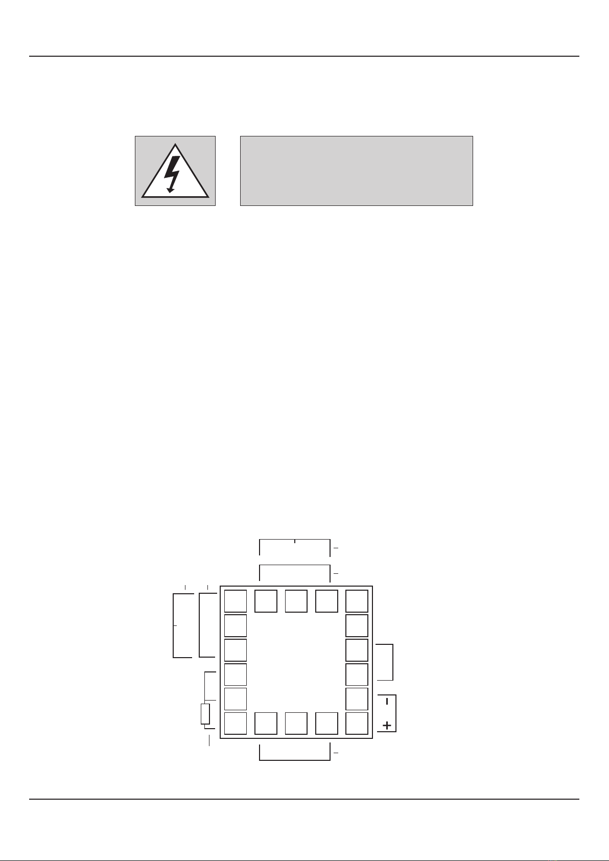
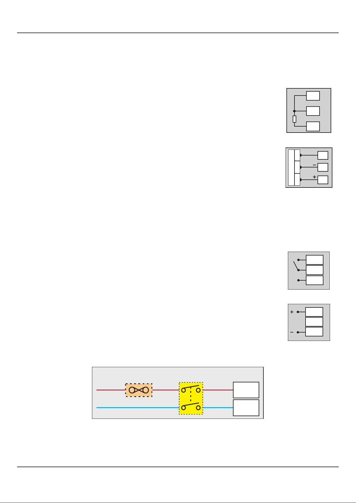
POWER SUPPLY Figure 10.4
The indicator is supplied with power connections suited for 85 to 264 VAC line supply. Use well-insulated copper conductor
2
wire of the size not smaller than 0.5mm for power supply connections. Connect Line (Phase) supply line to terminal 12 and the
Neutral (Return) supply line to terminal 13 as shown in Figure 10.4 above. The indicators is not provided with fuse and power
switch. If necessary, mount them separately. Use a time lag fuse rated 1A @ 240 VAC.
User Manual
HumiTherm-i (Dry-Wet)
Line
Neutral
12 (L)
13 (N)
2 Pole
Isolating Switch
Fuse
Power Supply
Terminal