PPI neuro 100Z User manual
neuro 100Z
User Manual
Enhanced Range (-19999 to +99999)
Universal Process Indicator

CONTENTS
User Manual
neuro 100 Z
1. FRONT PANEL LAYOUT 1
2. BASIC OPERATION 3
3. SET-UP MODE ACCESS AND OPERATION 5
4. ALARM PARAMETERS 7
5. RETRANSMISSION PARAMETERS 9
6. INPUT CONFIGURATION 10
7. SUPERVISORY PARAMETERS 13
8. HARDWARE ASSEMBLY & CONFIGURATIONS 14
9. MECHANICAL INSTALLATION 21
10. ELECTRICAL CONNECTIONS 23

1
FRONT PANEL LAYOUT
The indicator front panel comprises of digital readouts, LED indicators and tactile keys as shown in Figure 1.1 below.
READOUTS
The Upper Readout is a 5 digit, 7-segment bright red LED display and usually displays the PV (Process Value). In Set-up
Mode, the Upper Readout displays parameter values/options.
The Lower Readout is a 5 digit, 7-segment bright green LED display and usually displays Process Value Units. In case of any
active Alarm(s), the Lower Readout flashes Alarm Status information. In Set-up Mode, the Lower Readout displays the names
(identifier tags) for the parameters.
INDICATORS
The front panel comprises 4 LED indicators that show Alarm status. Refer Table 1.1 below for details.
Table 1.1
Flashes while Alarm-1 is active.
AL1
AL2 Flashes while Alarm-2 is active.
LED Status
AL3 Flashes while Alarm-3 is active.
AL4 Flashes while Alarm-4 is active.
User Manual
neuro 100 Z
Figure 1.1
Upper Readout
Lower Readout
Enter Key
Up Key
Down Key
Page Key
Alarm-3 Status
Alarm-1 Status
PPI
neuro 100 Z
ACK OPR
AL3 AL4
AL1 AL2 Alarm-2 Status
Alarm-4 Status
Alarm Acknowledge Key Operator Key
Section 1

2
Table 1.2
User Manual
neuro 100 Z
KEYS
There are six tactile keys provided on the front panel for configuring the indicator, setting-up the parameter values and
selecting Operation / Display Modes. Refer Table 1.2 below.
OPR
ACK
ENTER
Symbol Key Function
PAGE
DOWN
UP
Press to access ‘Operator-Page’ parameters.
(The parameters are listed and described in section 2 :
Basic Operation)
Press to store the set parameter value and to scroll to the next
parameter on the PAGE.
Press to enter or exit set-up mode.
Press to increase the parameter value. Pressing once
increases the value by one count; keeping pressed speeds up
the change.
Press to decrease the parameter value. Pressing once
decreases the value by one count; keeping pressed speeds up
the change.
OPERATOR
PAGE
ALARM
ACKNOWLEDGMENT
Press to acknowledge any pending Alarm(s). This also turns-
off the Alarm relay.
3
BASIC OPERATION
Table 2.1
PV above Max. Range
PV below Min. Range
Message Error Type Cause
Under-range
Over-range
ALARM STATUS UNDER PV ERROR CONDITIONS
For Alarm activation, the under-range condition is treated as minimum PV, whereas the over-range and open conditions are
treated as maximum PV. Thus, Process High Alarm turns ON under Over-range/Open error. Similarly, Process Low Alarm
turns ON under Under-range error.
OPERATOR PAGE AND PARAMETERS
The parameters that require frequent settings are organized on a separate page, called the Operator Page. The availability of
operator parameters is controlled at supervisory level and the parameter setting cannot be locked by the Master Lock.
Accessing Operator Page & Adjusting Parameters
Step through the following sequence to open the Operator Page and to adjust the operator parameter values.
1. Press and release ‘OPR’ key. The Lower Readout shows prompt for the first available operator parameter and the Upper
Readout shows value for the parameter.
2. Use UP/DOWN keys to adjust the value and then press ENTER key to store the set value and scroll to the next parameter.
The automatically reverts to MAIN Display Mode upon scrolling through the last operator parameter. indicator
Alternatively, use PAGE key to return to MAIN Display Mode.
Note:
The Operator Page can also be accessed through PAGE-0. (The pages and parameters are explained in next section).
The operator parameters are described in Table 2.2. Note that the parameters presented on Operator Page depend upon the
functions selected/enabled and supervisory level permissions.
The operator parameter list includes Setpoint Values for all 4 Alarms ( Alarm-1 to Alarm-4).
User Manual
neuro 100 Z
POWER-UP
Upon power-up, all displays and indicators are lit on for approximately 3 seconds. This is followed by the indication of the
indicator model name on the Upper Readout and the firmware version on the Lower Readout, for
approximately 1 second.
MAIN DISPLAY MODE
After the Power-up display sequence, the Upper Readout starts showing the measured PV (Process Value) and the Lower
Readout displays the user set Units for Process Value. This is the MAIN Display Mode that shall be used most often.
Alarm Status Information
In case of any Alarm (or Alarms) becoming active, the Lower Readout flashes the related Alarm details in the format ‘Ax.YY’,
where x is the Alarm Number (1, 2, 3 or 4) and YY is Alarm Type (Lo or Hi) For example means Alarm-1 is active and
the set Alarm Type is Low. In case of multiple Alarms, each Alarm Status is flashed sequentially with 3 Seconds time interval.
PV Error Indications
The PV Error type is flashed on the Upper Readout. For different errors and the causes, refer Table 2.1 below.
Section 2
4
User Manual
neuro 100 Z
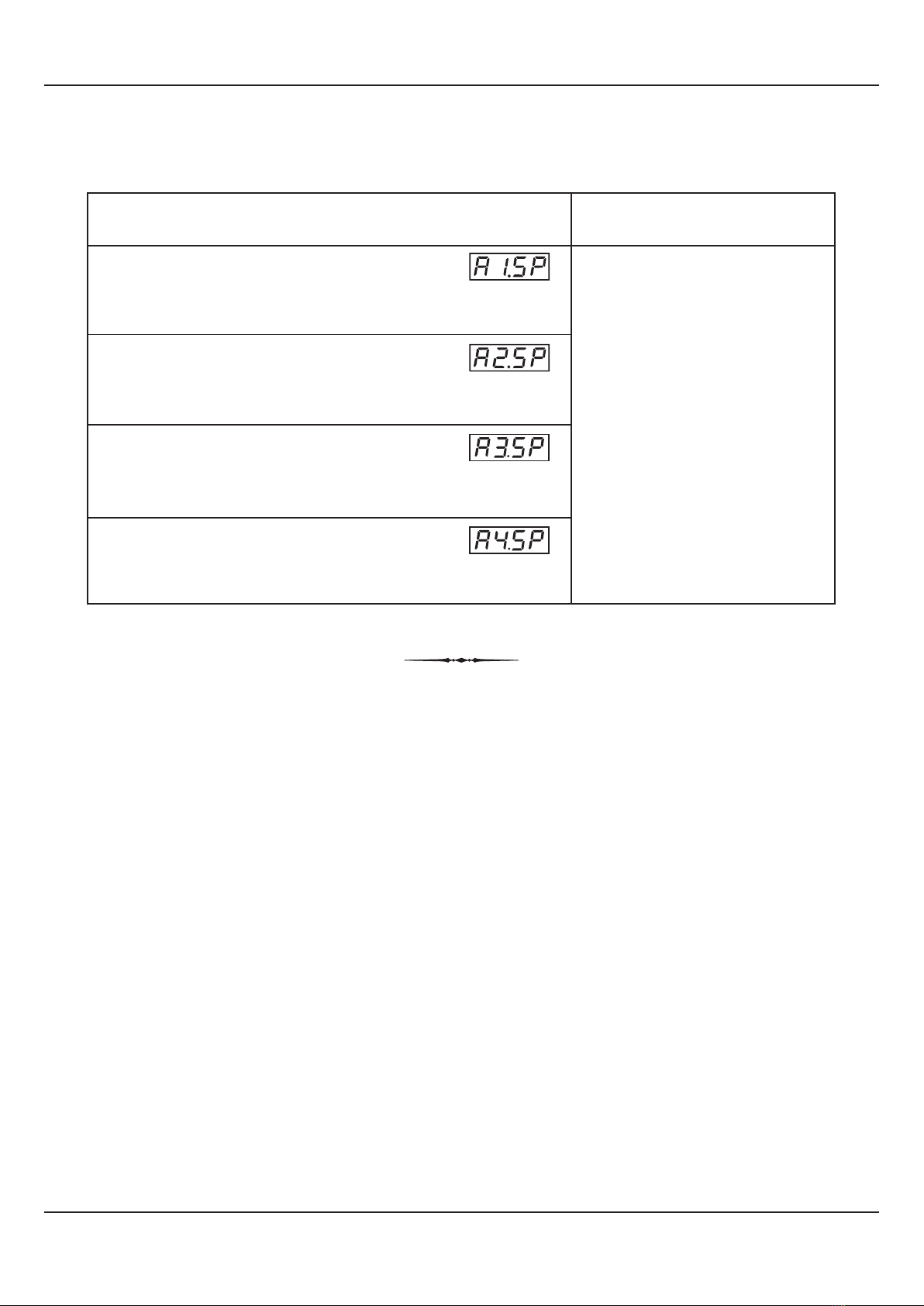
Table 2.2
Throughout the range for
the selected Input Type.
(Default :
For Process Low : -200.0
For Process High : 1376.0)
Parameter Description Settings
(Default Value)
ALARM-1 SETPOINT
The setpoint for Alarm-1. This parameter is not available if the
selected Alarm type for Alarm-1 is ‘None’.
ALARM-2 SETPOINT
The setpoint for Alarm-2. This parameter is not available if the
selected Alarm type for Alarm-2 is ‘None’.
ALARM-3 SETPOINT
The setpoint for Alarm-3. This parameter is not available if the
selected Alarm type for Alarm-3 is ‘None’.
ALARM-4 SETPOINT
The setpoint for Alarm-4. This parameter is not available if the
selected Alarm type for Alarm-4 is ‘None’.
5
The various parameters are arranged in different groups, called PAGES, depending upon the functions they represent. Each
group is assigned a unique numeric value, called PAGE NUMBER, for its access.
The parameters are always presented in a fixed format: The Lower Readout displays the parameter prompt (Identification
Name) and the Upper Readout displays the set value. The parameters appear in the same sequence as listed in their
respective sections.
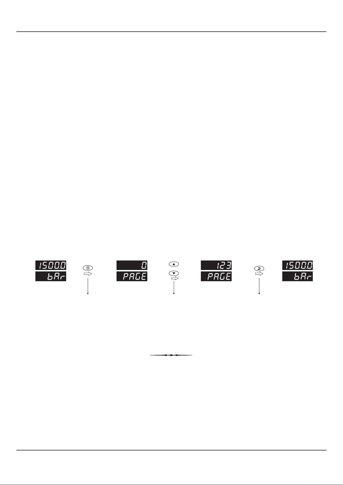
SET-UP MODE
The Set-up Mode allows the user to view and modify the parameter values. Follow the steps below for setting the parameter
values:
1. Press and release PAGE key. The Lower Readout shows PAGE and the Upper Readout shows page number 0. Refer
Figure 3.1.
2. Use UP / DOWN keys to set the desired PAGE NUMBER.
3. Press and release ENTER key. The Lower Readout shows the prompt for the first parameter listed in the set PAGE and the
Upper Readout shows its current value. If the entered PAGE NUMBER is invalid (contains no parameter list or any
associated function), the reverts to the MAIN Display Mode.indicator
4. Press and release the ENTER key until the prompt for the required parameter appears on the Lower Readout. (The last
parameter in the list rolls back to the first parameter).
5. Use UP / DOWN keys to adjust the parameter value. (The display flashes if UP key is pressed after reaching the maximum
value or DOWN key is pressed after reaching the minimum value).
6. Press and release the ENTER key. The new value gets stored in the indicator’s non-volatile memory and the next
parameter in the list is displayed.
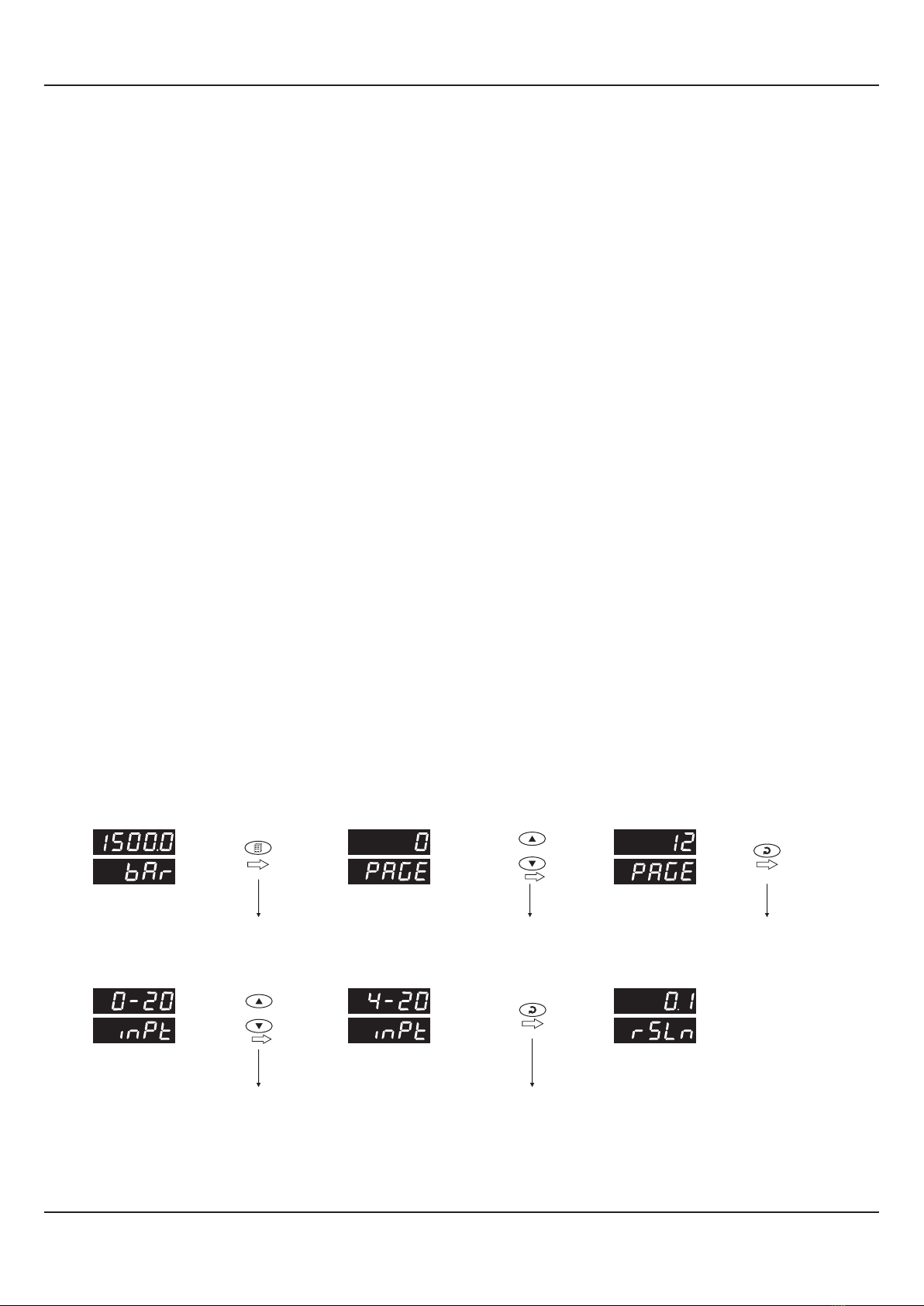
The Figure 3.1 illustrates the example of altering the value for the parameter ‘Input type’.
SET-UP MODE : ACCESS AND OPERATION
User Manual
neuro 100 Z
Figure 3.1
Section 3
Press PAGE
key to enter Set-up mode
Press ENTER
key to open the Page
Use UP/DOWN
keys to set the Page Number
Default Page Page NumberMAIN Display
Mode
Use UP/DOWN
keys to change the value
Press ENTER key
to store the value &
move to next parameter
First Parameter
on PAGE-12
Next Parameter
on PAGE-12
New Parameter
value
or
or
6
Notes
1. Each page contains a fixed list of parameters that are presented in a pre-determined sequence. Note however that availability of a few
parameters, called Conditional Parameters, depend upon the settings for some other parameters. For example, the parameter ‘Alarm
Setpoint’ is available if corresponding ‘Alarm type’ is set to other than ‘none’.
2. To exit the set-up mode and return to the MAIN Display Mode, press and release PAGE key.
3. If no key is pressed for approximately 30 seconds, the set-up mode times out and reverts to the MAIN Display Mode.
MASTER LOCKING
The indicator facilitates locking all the PAGES (except Operator PAGE) by applying Master Lock Code. Under Locking, the
parameters are available for view only and cannot be adjusted. The Master Lock, however, does not lock the operator
parameters. This feature allows protecting the rather less frequently used parameters against any inadvertent changes while
making the frequently used operator parameters still available for any editing.
For enabling / disabling the Lock, step through the following sequence:
Locking
1. Press and release PAGE key while the indicator is in the MAIN Display Mode. The Lower Readout shows PAGE and the
Upper Readout shows 0.
2. Use UP / DOWN keys to set the Page Number to 123 on the Upper Readout.
3. Press and release ENTER key. The indicator returns to the MAIN Display Mode with the Lock enabled.
The Figure 3.2 below illustrates the Locking procedure.
Figure 3.2
UnLocking
Repeat the Locking procedure twice for unlocking.
User Manual
neuro 100 Z
Press PAGE
key to enter Set-up mode
Use UP/DOWN
keys to set the ‘Locking’ Code
Press ENTER key to
Lock & Return to MAIN Mode
Default Page Locking Code MAIN Mode
MAIN Mode
or

7
ALARM PARAMETERS
Visit www.ppiindia.net for technical notes on ALARM for detailed understanding of the parameters / terminologies
used for describing the Alarm parameters in this section.
The parameters required for configuring Alarms are grouped on PAGE-10. The configuration includes selecting the type of
Alarm, setting the hysteresis value, enabling / disabling start-up Alarm suppression, etc. Refer Table 4.1 for parameter
description & settings.
Table 4.1
User Manual
neuro 100 Z
Settings
(Default Value)
Parameter Description
ALARM INHIBIT
Yes
The Alarm activation is suppressed until the PV is within Alarm
limits from the time the indicator is switched ON. This allows
suppressing the Alarm during the start-up Alarm conditions.
No
The Alarm is not suppressed during the start-up Alarm conditions.
ALARM HYSTERISIS
This parameter value sets a differential (dead) band between the
ON and OFF Alarm states. Keep it large enough to avoid frequent
switching of the Alarm relay.
ALARM SET POINT
This parameter sets the Process High or Process Low limit for
Alarm.
ALARM NUMBER
Select Alarm Number for parameter setting. For example; setting
the value to 1, selects Alarm-1.
ALARM TYPE
None
Disable the Alarm .
Process Low
The Alarm activates when the PV equals or falls below the ‘Alarm
Setpoint’ value.
Process High
The Alarm activates when the PV equals or exceeds the ‘Alarm
Setpoint’ value.
1 to 4
(Default : 1)
-19999 to +99999 Counts
(Default : )0
None
Process Low
Process High
(Default : None)
(Default : 2 Counts)
1 to 30000 Counts
Section 4
No
Yes
(Default : No)

8
User Manual
neuro 100 Z
Settings
(Default Value)
Parameter Description
ALARM LATCH
No
The Relay switches ON/OFF with Alarm switching.
Yes
The Relay Output switches (ON for Normal Logic / OFF for
Reverse logic) upon Alarm activation. However, Alarm de-
activation does not affect the Relay status. The Relay status can
only be regained by pressing ‘Acknowledge-key’ provided the
Alarm has de-activated.
ALARM LOGIC
Select ‘Normal’ if Alarm is to activate an Audio / Visual alarm.
Select ‘Reverse’ if Alarm is to Trip the system. Reverse
Normal
(Default : Normal)
No
Yes
(Default : No)

9
RETRANSMISSION PARAMETERS
The parameters required for configuring Retransmission are grouped on PAGE-11. The configuration includes selecting the
Output type, Recorder Low & High settings etc. Refer Table 5.1 for parameter description & settings.
Note that the Parameters on this page are presented only if Retransmission feature is enabled on Supervisory Level.
Table 5.1
Settings
(Default Value)
Parameter Description
User Manual
neuro 100 Z
RECORDER HIGH
Set the Higher PV Limit that shall correspond to the maximum
recorder output signal level (20 mA / 10 V / 5 V).
(Default : 0 Counts)
Min. to Max. Counts
Set the Lower PV Limit that shall correspond to the minimum
recorder output signal level (0 mA / 4 mA / 0 V).
RECORDER LOW
(Default : 0 to 20 mA)
0 to 20 mA
4 to 20 mA
0 to 5 Volts
0 to 10 Volts
RECORDER OUTPUT TYPE
Select type in accordance with the hardware module fitted. Select
0-20 or 4-20 mA, if Current output module is fitted. Select 0-5 or 0-
10 V, if Voltage output module is fitted.
(Default : 10000 Counts)
Min. to Max. Counts
Section 5

10
INPUT CONFIGURATION PARAMETERS
The indicator needs to be appropriately configured for Sensor/Transmitter Input type, PV indication, digital filter etc. The
PAGE-12 parameters are listed below in Table 6.1.
Table 6.1
Settings
(Default Value)
Parameter Description
DIGITAL FILTER
Sets the time constant, in Seconds, for the low-pass digital filter
applied to the measured PV. The filter helps smoothing /
averaging the signal input and removing the undesired noise. The
higher the filter value the lower the indication response to the PV
changes and vice-a-versa.
0.5 to 60.0 Seconds
(in steps of 0.5 Seconds)
(Default : 2.0 sec.)
(Default : )EU
Refer Table 6.2
Refer Table 6.3
(Default : 0.1)
Select Input type in accordance with the output signal form the
connected Sensor/Transducer. Ensure proper hardware jumper
settings.
INPUT TYPE
Set the Process Value indication resolution (decimal point). All the
resolution based parameters (hysteresis, alarm setpoints etc.)
then follow this resolution setting.
RESOLUTION
Select appropriate Units from the list in Table 6.2. Note however
that the selected Units are for the purpose of Lower Readout
indication only.
UNITS
Refer Table 6.3
(Default : 0-20 mA)
PV RANGE HIGH
Sets process value corresponding to maximum signal output from
the connected Sensor/Transducer (e.g., 5 V, 10 V, 20 mA, etc.).
OFFSET
This value is algebraically added to the measured PV to derive the
final PV that is displayed and used for Alarm / Retransmission.
Final PV = Measured PV + Offset
-19999 to +99999
(Default : 1000.0)
PV RANGE LOW
Sets process value corresponding to minimum signal output from
the connected Sensor/Transducer (e.g., 0 V, 0 mA, 4 mA, etc.).
-19999 to +99999
(Default : 0.0)
For DC Lin. Volts/Current
-19999 to +99999 Counts
(Default : 0)
User Manual
neuro 100 Z
Section 6
11
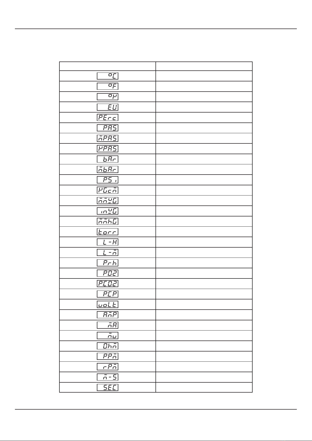
Table-6.2
°C
°F
Kelvin
Engineering Units
Percentage
Pascals
Mpascals
Kpascals
Bar
Milli bar
PSI
kg/sq cm
mm water gauge
Inches water gauge
mm mercury
Torr
Liters per hour
Liters per minute
% Relative Humidity
% O2
% Co2
% Carbon Potential
volts
Amps
Milli amps
Milli Volts
Ohms
Parts per million
Revolutions per pinute
Milli seconds
Seconds
Lower Readout Units
User Manual
neuro 100 Z
12
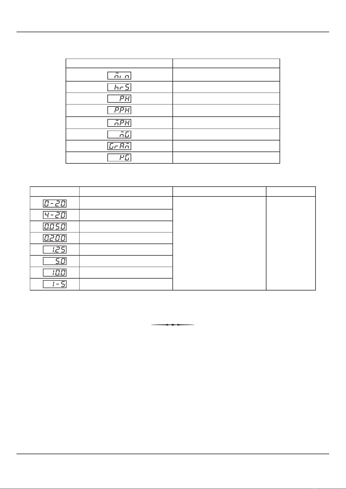
Table 6.3
-19999 to +99999 units
1
0.1
0.01
0.001
units
Option
Resolution
What it means Range (Min. to Max.)
0 to 50mV DC voltage
0 to 200mV DC voltage
0 to 1.25V DC voltage
0 to 5.0V DC voltage
0 to 10.0V DC voltage
1 to 5.0V DC voltage
0 to 20mA DC current
4 to 20mA DC current
Miles per hour
Milli grams
Grams
Kilo grams
Lower Readout Units
Minutes
Hours
PH
%PH
User Manual
neuro 100 Z

13
SUPERVISORY PARAMETERS
The supervisory level responsibilities include exercising control over operator, making process related decisions and
controlling the availability of process data for remote use. The PAGE-13 parameters allow implementation of supervisory level
decisions. The Table 7.1 below lists supervisory parameters.
User Manual
neuro 100 Z
Table 7.1
BAUD RATE
Communication speed in ‘Bits per Second’. Set the value to match
with the host baud rate.
Settings
(Default Value)
Parameter Description
Supervisory permission for enabling recorder (retransmission)
output.
RECORDER
Supervisory permission for Alarm setpoint adjustments on
Operator Page. Set to ‘Enable’ for permission.
ALARM SP ADJUSTMENT
ON OPERATOR PAGE
Supervisory permission for use of the rear panel terminals for
connecting remote switch for Alarm acknowledge.
REMOTE ACKNOWLEDGE SWITCH
Enable
Disable
(Default : Disable)
4800
9600
19200
38400
57600
(Default : 9.6)
PARITY
One of the communication error trapping features. Select the data
packet parity as implemented by the host protocol.
None
Even
Odd
(Default : Even)
SERIAL WRITE PERMISSION
Setting to ‘No’ disallows the host to set / modify any parameter
value. The host, however, can read the value.
SERIAL ID NUMBER
Unique numeric code assigned to the for identification by indicator
the host. Set the value as required by the host.
1 to 127
(Default : 1)
No
Yes
(Default : No)
Section 7
Enable
Disable
(Default : Disable)
Enable
Disable
(Default : Disable)
14
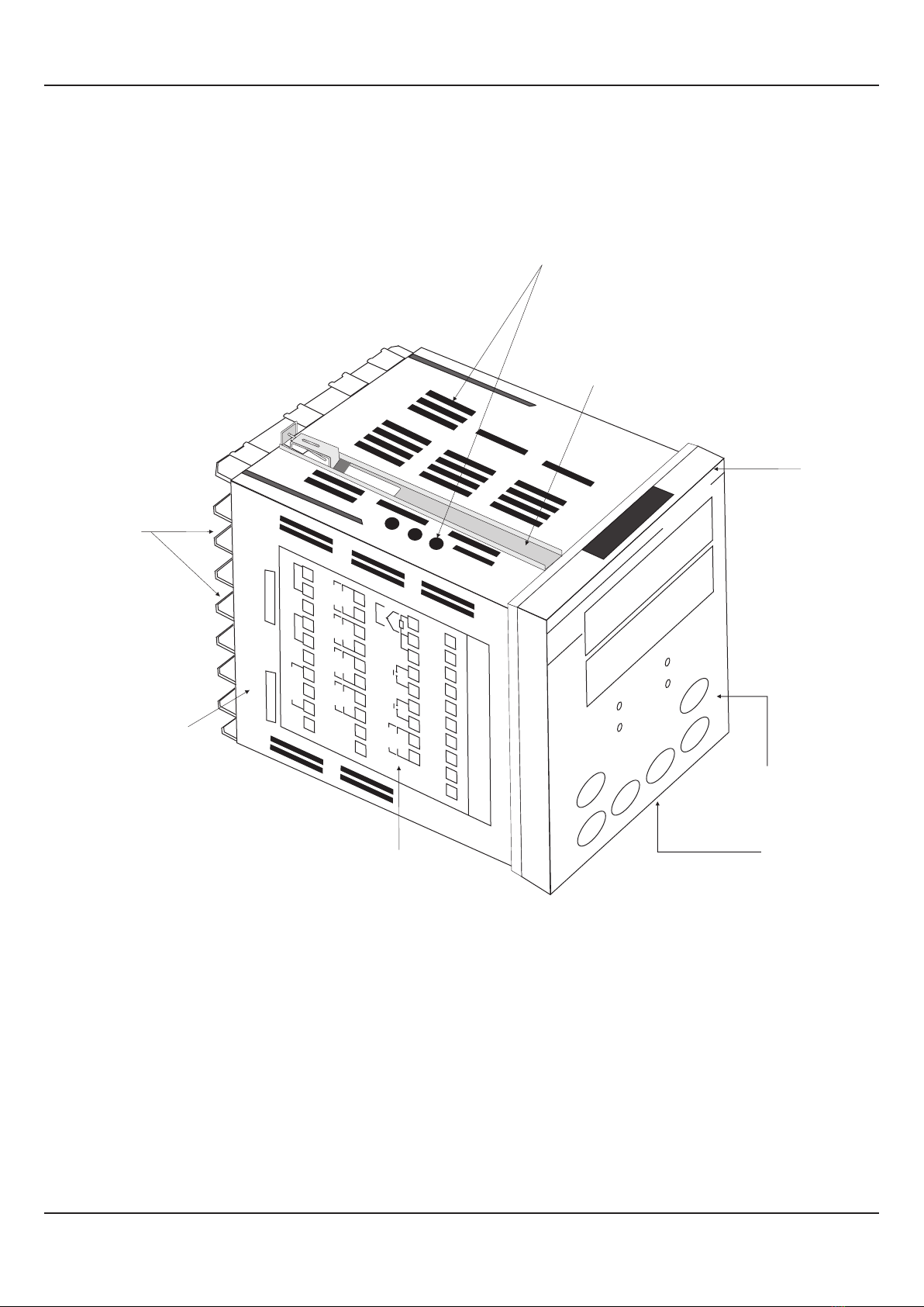
HARDWARE ASSEMBLY AND CONFIGURATIONS
The Figure 8.1 below shows the indicator outer-case viewed with front label upright.
ELECTRONIC ASSEMBLY
The basic electronics assembly (without any plug-in modules), comprises of 4 Printed Circuit Boards (PCB). When viewed
from the front; the CPU PCB is to the left, Power-supply PCB is to the right, Output PCB is in the center and the Display PCB is
behind the bezel.
The electronic assembly can be removed from the plastic enclosure and placed back as described and illustrated in Figure
8.2.
Figure 8.1
PPI
neuro 100 Z
+
+
+–
–
–+–
NO CNO NO NO
CCC
RLYRLYRLYRLY
SSR / DC Lin
OP-1
SSR / DC Lin
OP-2 OP-3 OP-4
SSR SSR
21
22
23
24
25
26
27
28
29
30
11
12
13
14
15
16
17
18
19
20
+–
LN
Ext. Voltage
B+ B–GND
SERIAL COMM
85 to 265 VAC
1
2
3
4
5
6
7
8
9
10
+–
+
+––
NO C
RLY
DC LINEAR
DI-1 DI-2
SSR / DC Lin
OP-5
T/C
Pt100
31
32
33
34
35
36
37
38
39
PPI
neuro 102 Z
Sr.No.:
IO Code:
Ventilations
Bezel
Front Label
Connection Diagram
Rear
Terminals
Enclosure
Panel Mounting
Clamp
Pullout
Latch
User Manual
neuro 100 Z
Section 8

15
Figure 8.2
Removing Assembly from Enclosure
Hold the indicator upside down and press the pullout latch to unlock the front bezel from the enclosure (Refer Figure 8.2
above). Pull the bezel outward. The electronics assembly comes out with the bezel.
Placing Assembly Back into Enclosure
Hold the Enclosure and the Bezel such that the Latching Slot on the Enclosure and the Pullout Latch on the Bezel face upward
(See Figure 8.2). Insert the bezel gently into the Enclosure until the Bezel snap fits.
User Manual
neuro 100 Z
Removal
Placing Back
PulloutLatch
Latching Slot
PPI
neuro 100 Z
16
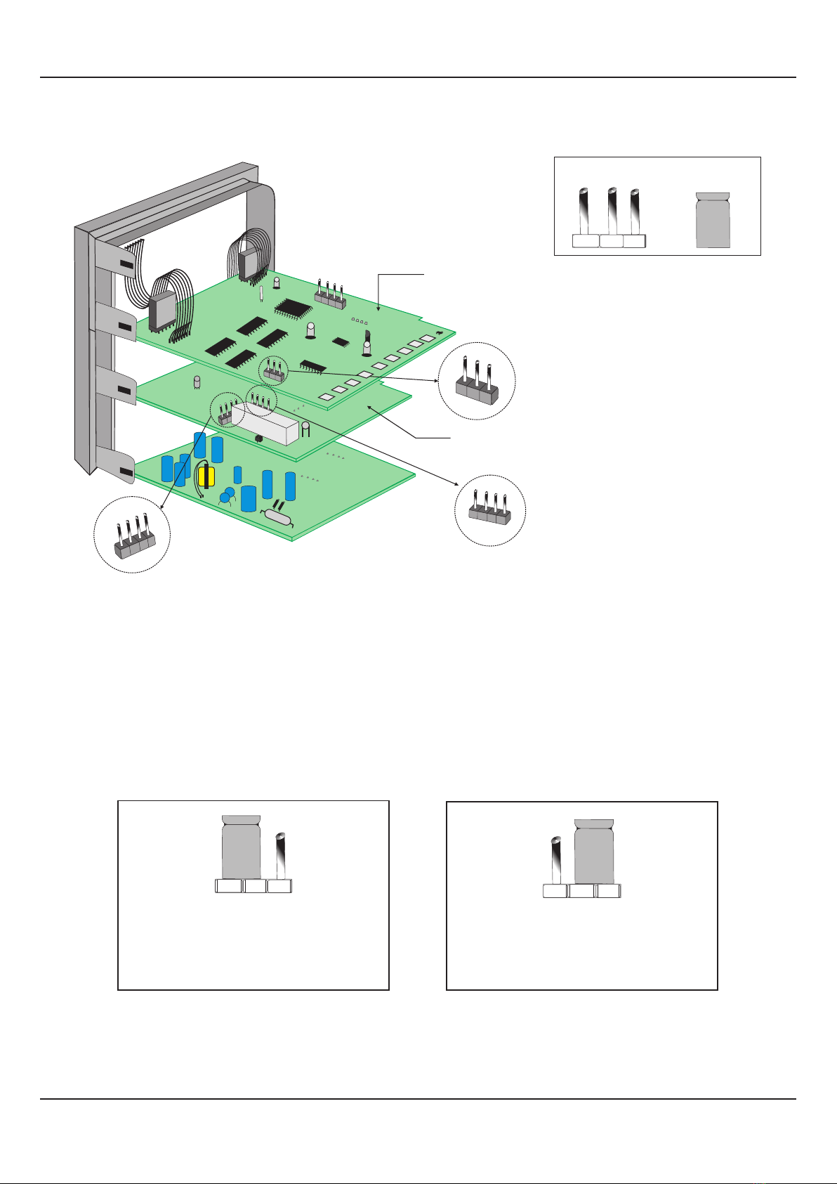
INPUT : Jumper Settings
In addition to parameter settings, the Input Type selection also requires proper jumper settings. For the jumper settings; Pins &
Shorting-Link arrangement, marked ‘A’, is provided on the CPU PCB as shown in Figure 8.3.
For DC Linear mV & V, Short the pins 1 & 2 using Shorting-Link as shown in Figure 8.4 (a).
For DC Linear Current Inputs (0-20 mA or 4-20 mA), short the Pins 2 & 3 using Shorting-Link as shown in Figure 8.4 (b).
Figure 8.4 (a)
For Input Types:
0-50mV, 0-200mV, 0-1.25V,
0-5V, 1-5V & 0-10V
123
Figure 8.4 (b)
For Input Types:
0-20mA & 4-20mA
123
OUTPUT-1 : Jumper Settings
The Output-1 Type is user selectable as Relay or SSR through proper jumper settings. The jumper settings are provided as
Pins & Shorting Link arrangement (marked ‘B’ & ‘C’) on Output PCB, as shown in Figure 8.3 and listed in Table 8.1 below.
Figure 8.3
User Manual
neuro 100 Z
Shorting
Link
Pins
CPU PCB
12 3
A
1 2 34
C
1234
Output PCB
Input
Jumper Settings
Output-1
Jumper Settings
Output-1
Jumper Settings
B
17
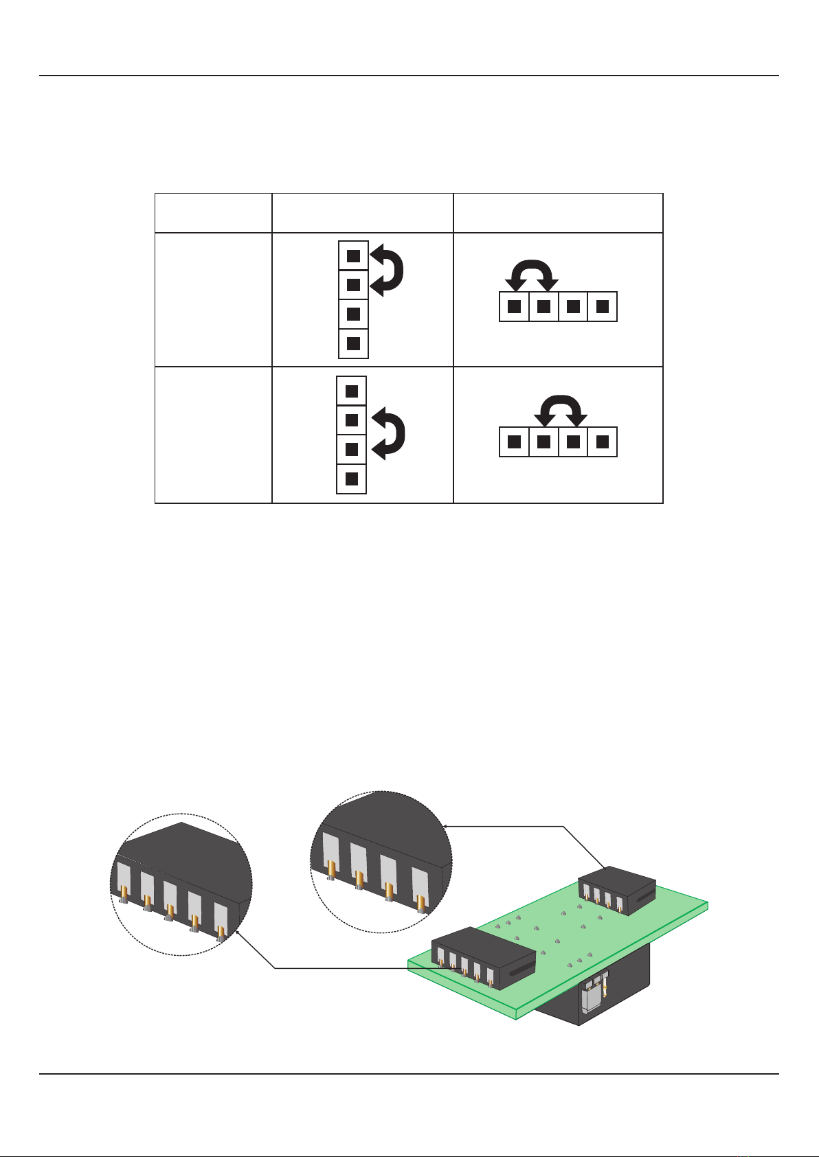
Output-1 Jumper Settings
OUTPUT PLUG-IN MODULES (OP2, OP3, OP4 & OP5)
The indicator supports 3 types of ‘Plug-in Modules’ that can be used as outputs (OP2, OP3, OP4 & OP5).The 3 types are; (a)
Relay /SSR Module, (b) DC Linear Voltage Module and (c)DC Linear Current Module. Each Module is provided with one 4-Pin
& one 5-Pin Female Socket that can directly fit into corresponding male plugs provided on either Output PCB (OP2, OP3 &
OP4) or CPU PCB (OP5). Refer Figure 8.5(a) & 8.5(b). These modules are either pre-fitted while the indicator is shipped from
the factory or can be fitted later by the user.
Table 8.1
5-Pin Female
Socket
4-Pin Female
Socket
Relay/SSR Module - Bottom View
Figure 8.5(a)
User Manual
neuro 100 Z
Relay
SSR Drive
1 2 3 4
1 2 3 4
1
2
3
4
1
2
3
4
Output Type Jumper Setting - C Jumper Setting - B
18
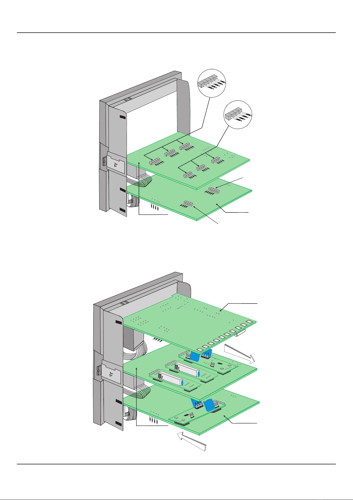
Mounting Parts for Output Modules
Figure 8.5(b)
User Manual
neuro 100 Z
Figure 8.6
Output PCB
5-Pin Male
Plug
4-Pin Male
Plug
OP2
OP3
OP4
5-Pin Male
Plug
4-Pin Male Plug
OP5
CPU PCB
Power-Supply
PCB
Placing Back
CPU PCB
Output PCB
Removal
OP5
OP2
OP3
OP4
Table of contents
Other PPI Measuring Instrument manuals


