PPI HumiTherm-i Pro User manual
User Manual
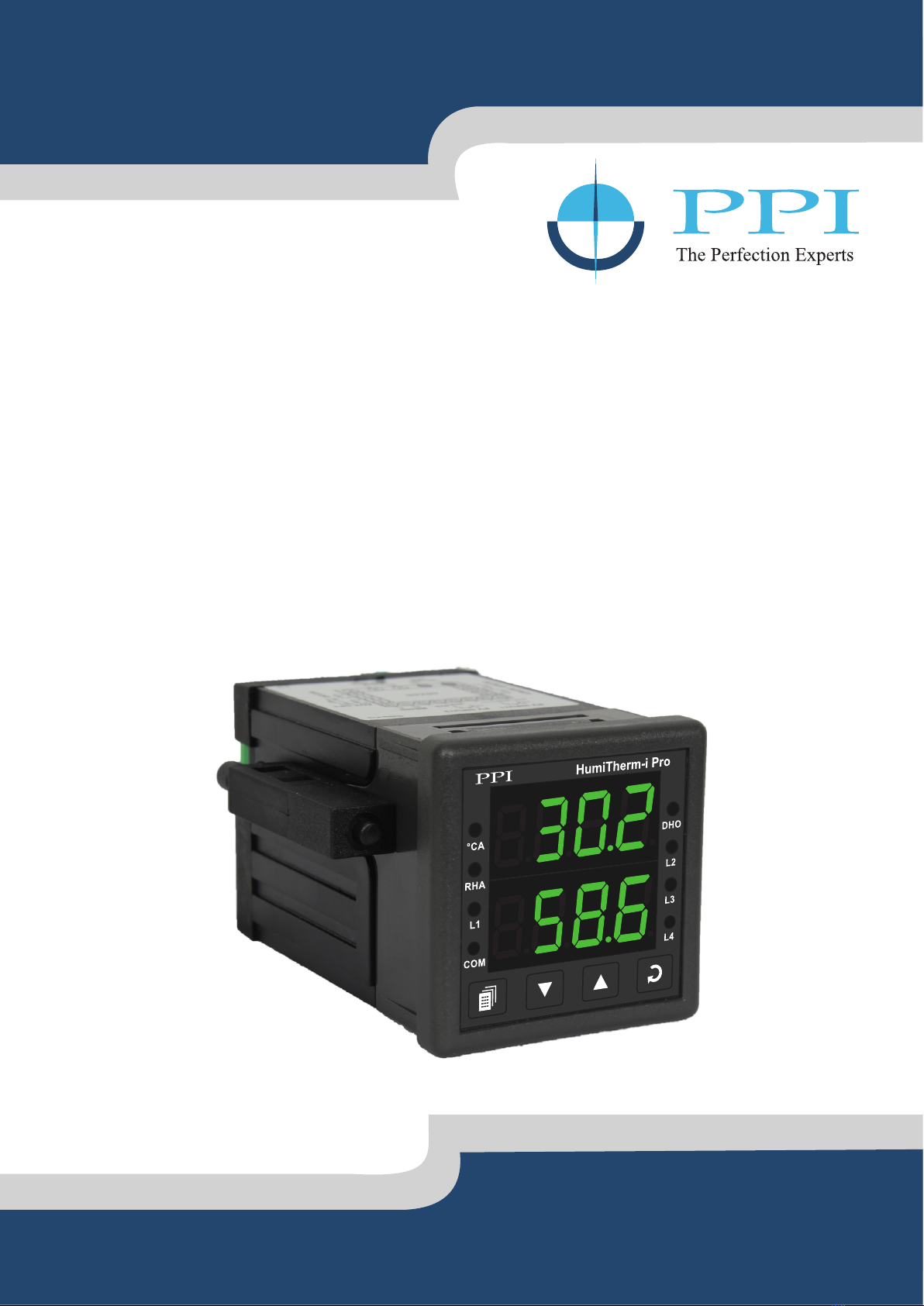
HumiTherm-i Pro
Enhanced
‘Temperature + Humidity’ Indicator
(with Dry/Wet RTD Input Selection)
User Manual
HumiTherm-i Pro

User Manual
HumiTherm-i Pro
CONTENTS
1. FRONT PANEL LAYOUT 1
2. BASIC OPERATION 3
3. SETUP MODE : ACCESS AND OPERATION 6
4. PAGE-10 : TEMPERATURE - ALARM PARAMETERS 8
5. PAGE-11 : RELATIVE HUMIDITY - ALARM PARAMETERS 9
6. PAGE-12 : INPUT CHANNEL CONFIGURATION PARAMETERS 10
7. PAGE-13 : SUPERVISORY PARAMETERS 13
8. PAGE-14 : DE-HUMIDIFIER CONTROL PARAMETER 14
9. MECHANICAL INSTALLATION 15
10. ELECTRICAL CONNECTIONS 17
User Manual
HumiTherm-i Pro
1
Section 1
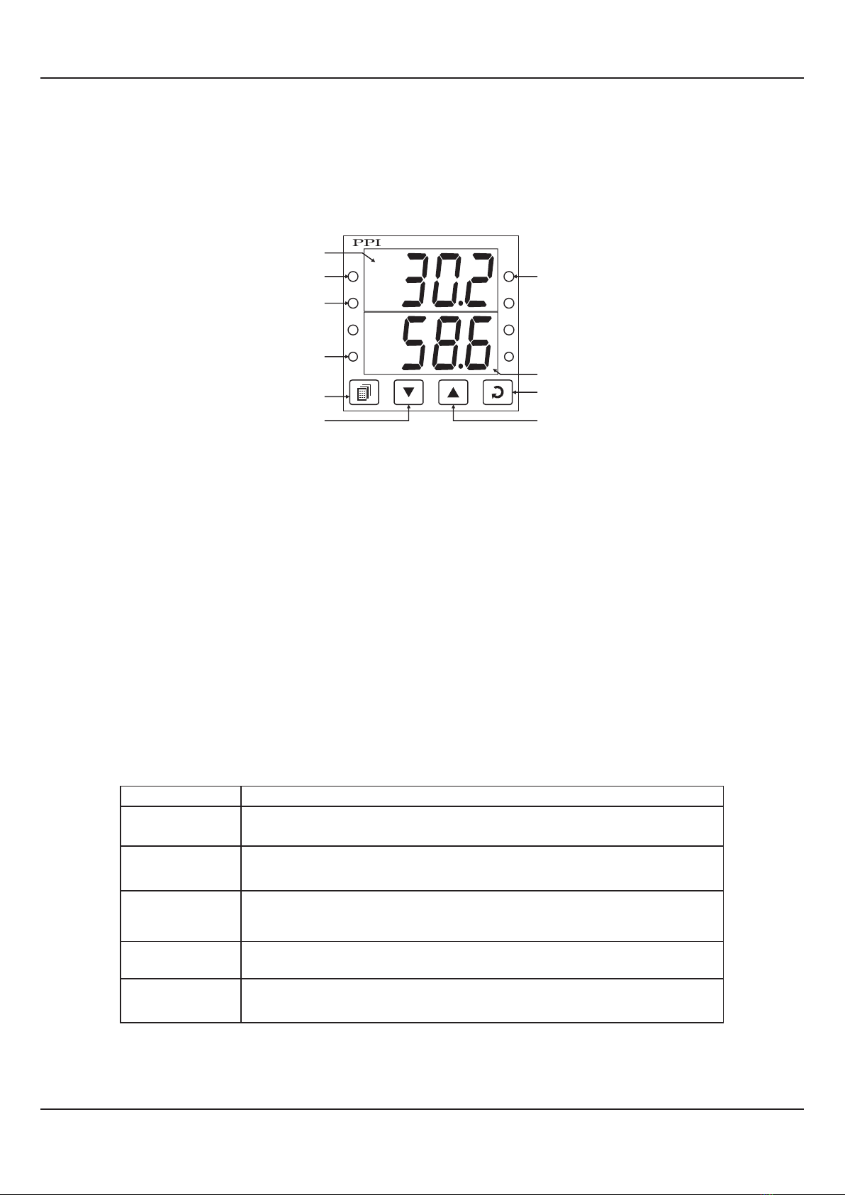
The indicator front panel comprises of digital readouts, LED indicators and membrane keys as shown in Figure 1.1 below.
READOUTS
The Upper Readout is a 4 digit, 7-segment bright green LED display and usually displays the Temperature Value in °C or °F
(depending upon the Unit selected). In Program Mode, the Upper Readout displays parameter values.
The Lower Readout is a 4 digit, 7-segment bright green LED display and usually displays Relative Humidity (RH) Value in %.
For Dry/Wet Configuration, upon holding the UP or DOWN key pressed, the Lower Readout shows the Wet-Bulb Temperature
in °C or °F. In Program Mode, the Lower Readout displays prompts for the parameters.
Table 1.2
Figure 1.1
FRONT PANEL LAYOUT
°CA
RHA
DHO
L2
HumiTherm-i Pro
L1 L3
L4COM
Upper Readout
Lower Readout
ENTER Key
UP Key
DOWN Key
PAGE Key
Serial Comm. Indicator
Temperature Alarm
Indicator
%RH Alarm Indicator
De-Humidifier
Output Indicator
Indicator Function
Temperature Alarm Status. Flashes when temperature alarm is active.
°CA
RHA %RH Alarm Status. Flashes when %RH alarm is active.
DHO
L1, L2,
L3, L4
Shows On/Off Status of de-humidifier control output.
Unused
COM Serial Communication Status. Flashes when data is being exchanged
with Master Device.
INDICATORS
There are 8 front panel red LED indicators (4 are unused). These indicator show various statuses. The Table 1.1 below lists
each LED indicator (identified by the front panel legend) and the associated status it indicates.

User Manual
HumiTherm-i Pro
2
KEYS
There are four tactile keys provided on the front panel for configuring the controller and setting-up the parameter values. The
Table 1.2 below lists each key (identified by the front panel symbol) and the associated function.
Table 1.2
Symbol Key Function
Press to enter or exit set-up mode.
DOWN
UP
ENTER Press to store the set parameter value and to scroll to the
next parameter on the PAGE.
Press to increase the parameter value. Pressing once
increases the value by one count; keeping pressed speeds
up the change.
Press to decrease the parameter value. Pressing once
decreases the value by one count; keeping pressed speeds
up the change.
PAGE
User Manual
HumiTherm-i Pro
3
BASIC OPERATIONS
POWER-UP
Upon power-up, all displays and indicators are lit on for approximately 3 seconds. This is followed by the indication of the
indicator model name (HUm.i) on the Upper Readout and the loaded firmware version on the Lower Readout, for
approximately 1 second.
MAIN DISPLAY MODE
After the Power-up display sequence, the Upper and Lower Readout start showing the measured Temperature Value in °C or
°F and the Relative Humidity in %RH, respectively. If the Indicator is configured for Dry/Wet assembly, the Wet Bulb
Temperature (in °C) can be viewed by holding the UP or DOWN key depressed. This is called the MAIN Display Mode and this
is the one that shall be used most often.
Section 2
PV ERROR INDICATIONS
The indicator flashes the PV error messages for Temperature and RH Values on Upper and Lower Readout, respectively.
§Error Indications for Dry-Bulb Temperature
In case of Dry-Bulb Temperature exceeding the specified Minimum or Maximum Range or in case of input sensor (RTD
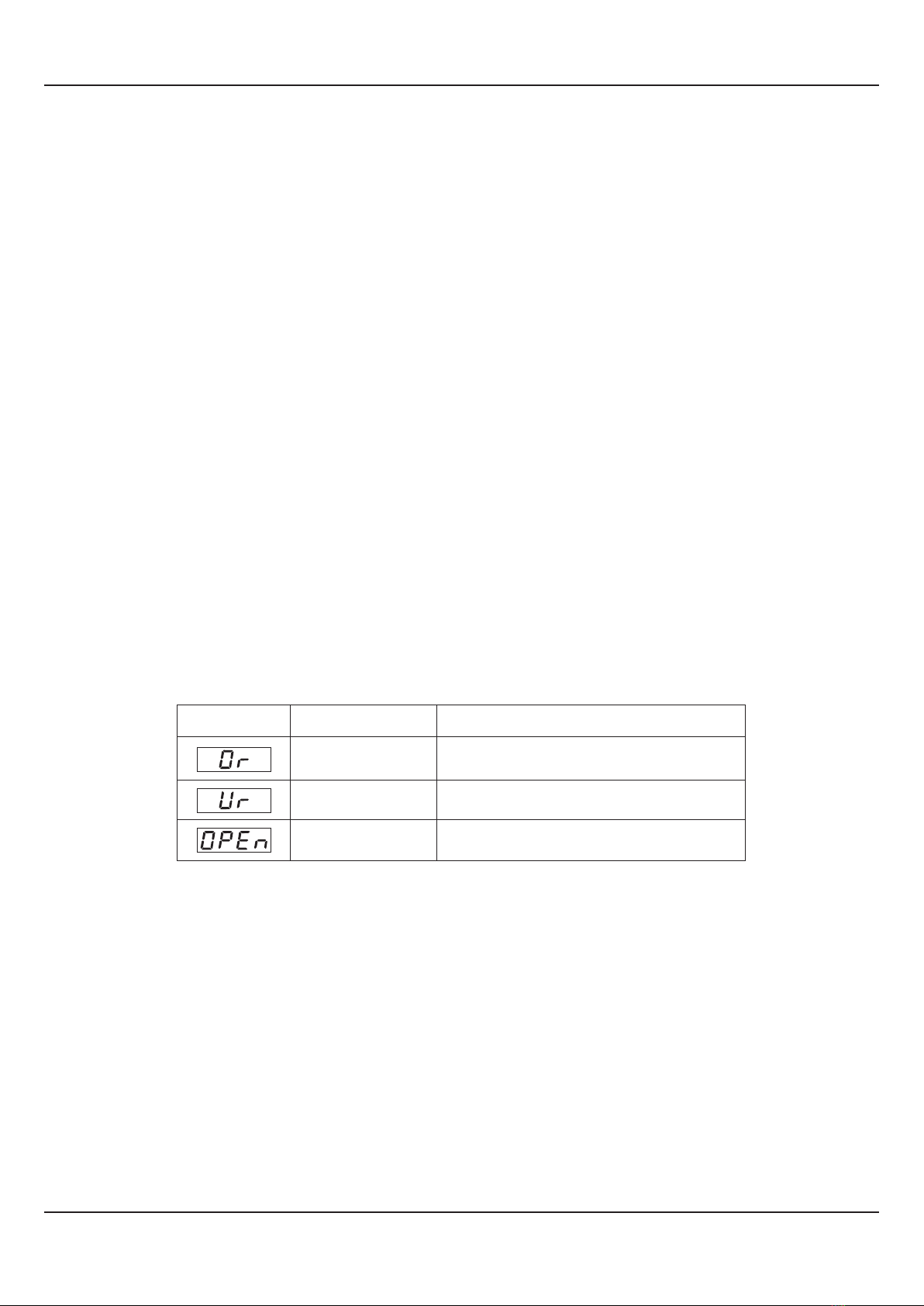
Pt100) open / broken; the Upper Readout flashes the Error Messages as listed in Table 2.1 below.
Table 2.1
Message Error Type Cause
Sensor Open
Under-range
Over-range Dry Bulb Temperature above Max. Range
Dry Bulb Temperature below Min. Range
Dry Bulb Sensor (RTD) Broken / Open
§ Error Indication for Relative Humidity (RH)
If RH transmitter is connected for direct %RH measurement, the signal output is either DC Voltage (e.g. 0 - 5 V, 0 - 10 V,
etc.) or DC Current (e.g. 4 - 20 mA). Thus, an open or broken sensor means either 0 V or 0 mA output. In this case the
indicator reads the %RH that corresponds to this signal output. For example, consider 0-5V signal scaled to display 0.0 to
100.0 %RH. The Upper Readout then shows approximately 0.0 %RH (corresponding to 0 V) upon sensor open / broken.
If Dry/Wet assembly is used for RH measurement and if either Wet-Bulb RTD is open / broken or there is an error condition
while computing %RH value, the Lower Readout flashes the Error Messages as listed in Table 2.2 below.

User Manual
HumiTherm-i Pro
4
Table 2.2
Note:
For both Dry and Wet Bulb, 3-wire RTD sensor input, if the compensating lead is not connected or gets open, the indicator does not indicate
PV error but the measured value is not compensated for the lead resistance.
Message Error Type Cause
Sensor Open
Under-range
Over-range Wet Bulb Temperature above Max. Range
Wet Bulb Temperature below Min. Range
Wet Bulb Sensor (RTD) Broken / Open
RH Error
Display Freezes
To 100.0%
This error is indicated in the following cases :
• Wet-Bulb Temperature exceeds Dry-Bulb Temperature.
• Computed % RH above 100.0%.
Display Freezes
To 0.0% Computed % RH is below 0.0%.
This error is indicated in the following cases :
• Dry Bulb Temperature above 102.0°C.
• Dry Bulb Temperature below -20.0°C.
• Wet Bulb depression beyond:
50.0°C for Dry Bulb Temperature above 0°C
5.6°C for Dry Bulb Temperature below 0°C
OPERATOR PAGE AND PARAMETERS
The indicator provides a separate page, called Operator Page, for the purpose of viewing and / or resetting the stored Min. /
Max. values for Dry- Bulb Temperature and %RH. The parameters on this page are available only if the Min. / Max. feature is
Enabled in Page -13 parameter list.
Accessing Operator Page
Step through the following sequence to open the operator page and to adjust the operator parameter values.
1. Press and release PAGE key. The Lower Readout shows (PAGE) and Upper Readout shows (0).
2. Press ENTER key. The Lower Readout shows prompt for the first available operator parameter and the Upper Readout
shows value for the parameter.
3. Use UP / DOWN keys to adjust the value and then press ENTER key to store the set value and scroll to next parameter.
The indicator automatically reverts to MAIN Display Mode upon scrolling through the last operator parameter. Alternatively,
use PAGE key to return to MAIN Display Mode.
The operator parameters are described in Table 2.3. Note that the parameters are presented only if ‘Min / Max Monitoring’
feature is enabled.

User Manual
HumiTherm-i Pro
5
Table 2.3
Parameter Description Settings
(Default Value)
View Only
MAXIMUM DRY BULB
TEMPERATURE VALUE
This parameter indicates the Maximum value attained by the Dry-
Bulb Temperature. This is a read only value.
View Only
MINIMUM DRY - BULB
TEMPERATURE VALUE
This parameter indicates the Minimum value attained by the Dry-
Bulb Temperature. This is a read only value.
View Only
MAXIMUM %RH VALUE
This parameter indicates the Maximum value attained by the
Relative Humidity. This is a read only value.
View Only
MINIMUM %RH VALUE
This parameter indicates the Minimum value attained by the
Relative Humidity. This is a read only value.
0 to 250
(Default : 0)
RESET PASS - CODE
For Resetting the Min. / Max. values, set the reset command to
‘Yes’ and then set this parameter value to the Pass - Code value
stored at Supervisory level on Page-13.
RESET COMMAND
This feature clears the current Min. / Max. values and starts afresh
monitoring the Process Values for new Min & Max. (Default : No)
No
Yes
User Manual
HumiTherm-i Pro
6
The various parameters are arranged in different groups, called PAGES, depending upon the functions they represent. Each
group is assigned a unique numeric value, called PAGE NUMBER, for its access.
The parameters are always presented in a fixed format: The Lower Readout displays the parameter prompt (Identification
Name) and the Upper Readout displays the set value. The parameters appear in the same sequence as listed in their
respective sections.
SET-UP MODE
The Set-up Mode allows the user to view and modify the parameter values. Follow the steps below for setting the parameter
values:
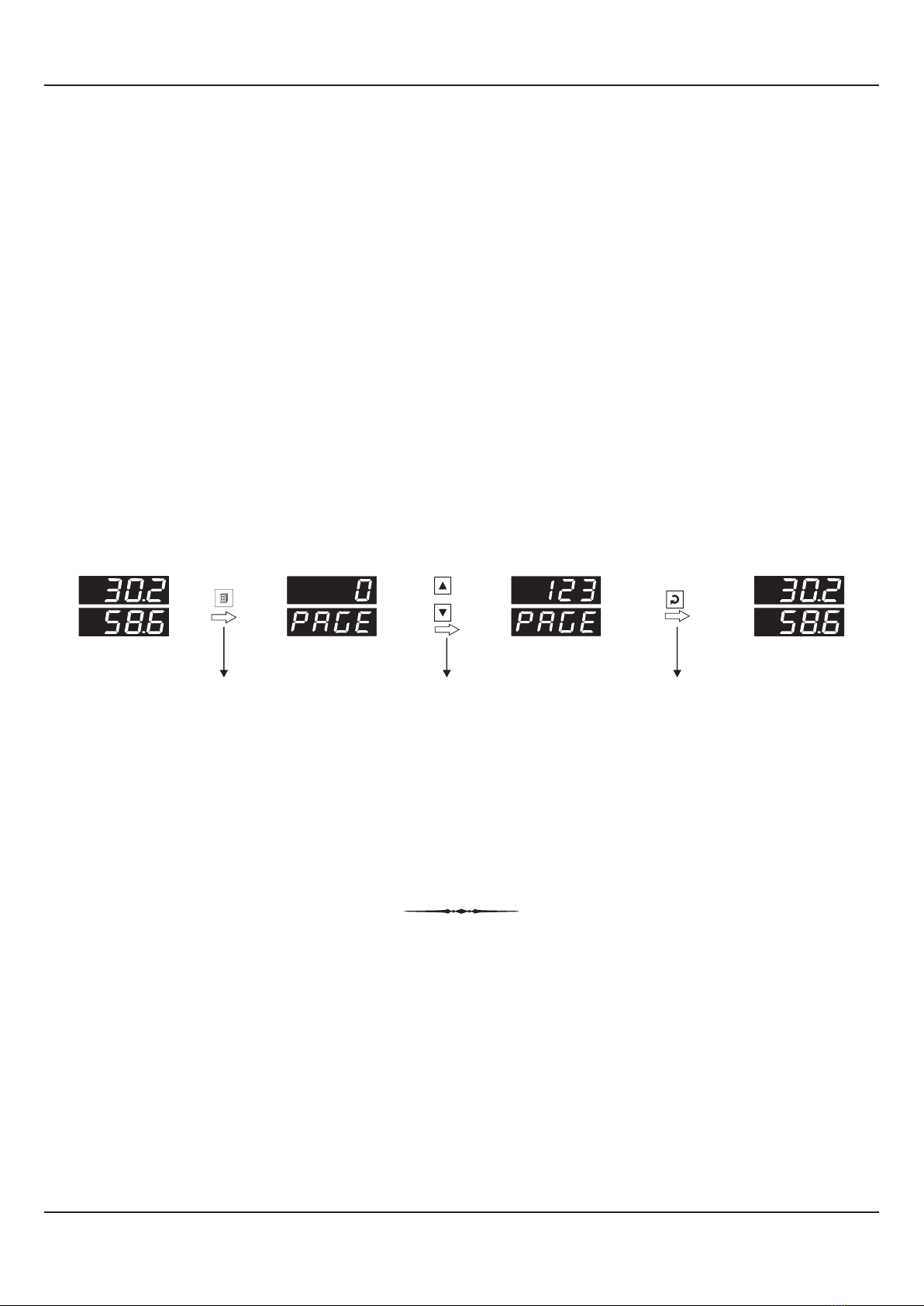
1. Press and release PAGE key. The Lower Readout shows PAGE and the Upper Readout shows page number 0. Refer
Figure 3.1.
2. Use UP / DOWN keys to set the desired PAGE NUMBER.
3. Press and release ENTER key. The Lower Readout shows the prompt for the first parameter listed in the set PAGE and
the Upper Readout shows its current value. If the entered PAGE NUMBER is invalid (contains no parameter list or any
associated function), the indicator reverts to the MAIN Display Mode.
4. Press and release the ENTER key until the prompt for the required parameter appears on the Lower Readout. (The last
parameter in the list rolls back to the first parameter).
5. Use UP / DOWN keys to adjust the parameter value. (The display flashes if UP key is pressed after reaching the maximum
value or DOWN key is pressed after reaching the minimum value).
6. Press and release the ENTER key. The new value gets stored in the indicator’s non-volatile memory and the next
parameter in the list is displayed.
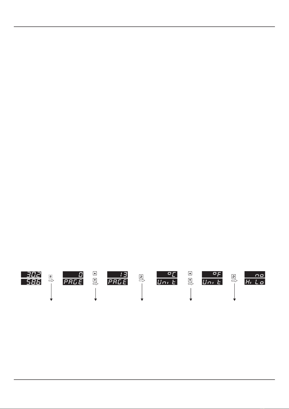
SET-UP MODE : ACCESS AND OPERATION
The Figure 3.1 illustrates the example of altering the value for the parameter ‘Units’ on PAGE-13.
Notes
1. Each page contains a fixed list of parameters that are presented in a pre-determined sequence. Note however that availability of a few
parameters, called Conditional Parameters, depend upon the settings for some other parameters. For example, the parameter ‘Control
Hysteresis’ for Output-1 is available only if, the set value for the parameter ‘Control Action’ is ‘On-Off’.
2. To exit the set-up mode and return to the MAIN Display Mode, press and release PAGE key.
3. If no key is pressed for approximately 30 seconds, the set-up mode times out and reverts to the MAIN Display Mode.
Figure 3.1
Section 3
Press PAGE
key to enter
Set-up Mode
Use UP/DOWN
key to set the
Page Number
Press ENTER
key to open
the Page
Use UP/DOWN
keys to change
the value
Press ENTER
key to store the value &
move to next parameter
or
Main Display
Mode
Default Page Page Number First Parameter
on Page-13
New Parameter
value
Next Parameter
on Page-13
or
User Manual
HumiTherm-i Pro
7
UnLocking
Repeat the Locking procedure twice for unlocking.
MASTER LOCKING
The indicator facilitates locking all the PAGES (except Operator PAGE) by applying Master Lock Code. Under Locking, the
parameters are available for view only and cannot be adjusted. The Master Lock, however does not lock the operator
parameters. This feature allows protecting the rather less frequently used parameters against any inadvertent changes while
making the frequently used operator parameters still available for any editing.
For enabling / disabling the Lock, step through the following sequence:
Locking
1. Press and release PAGE key while the indicator is in the MAIN Display Mode. The Lower Readout shows PAGE and the
Upper Readout shows 0.
2. Use UP / DOWN keys to set the Page Number to 123 on the Upper Readout.
3. Press and release ENTER key. The indicator returns to the MAIN Display Mode with the Lock enabled.
The Figure 3.2 below illustrates the Locking procedure.
Figure 3.2
or
MAIN Display
Mode
Default Page Locking Code MAIN Display
Mode
Press PAGE
key to enter
Set-up Mode
Use UP/DOWN
key to set the
‘Locking Code’
Press ENTER key
to Lock & Return to
Main Mode

User Manual
HumiTherm-i Pro
8
Reverse
Direct
(Default : Direct)
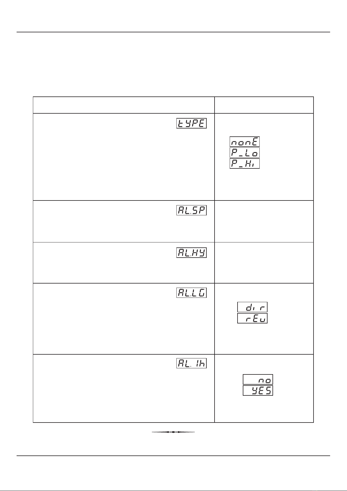
Table 4.1
PAGE-10 : TEMPERATURE - ALARM PARAMETERS
Parameter Description Settings
(Default Value)
-50.0 to 150.0°C or
-58.0 to 302.0°F
(Default :
For Process Low : -50.0
For Process High : 150.0)
(Default : 0.2)
0.1 to 25.0 °C or °F
TEMPERATURE ALARM TYPE
None
Alarm activation is disabled.
Process Low
The Alarm activates when the Temperature Value equals or falls
below the ‘Alarm Setpoint’ value.
Process High
The Alarm activates when the Temperature Value equals or
exceeds the ‘Alarm Setpoint’ value.
TEMPERATURE ALARM SETPOINT
This parameter sets the Process High or Process Low limit for
Alarm.
TEMPERATURE ALARM HYSTERESIS
This parameter sets a differential (dead) band between the ON
and OFF Alarm states. Keep it large enough to avoid frequent
switching of the Alarm relay.
(Default : Yes)
No
Yes
Section 4
TEMPERATURE ALARM INHIBIT
No
The Alarm is not suppressed during the start-up Alarm conditions.
Yes
The Alarm activation is suppressed until the Temperature Value is
within Alarm limits from the time the indicator is switched ON. This
allows suppressing the Alarm during the start-up Alarm
conditions.
(Default : None)
Process High
None
Process Low
TEMPERATURE ALARM LOGIC
Direct
Alarm Relay is energized when the alarm is active; remains de-
energized otherwise.
Reverse
Alarm Relay remains energized as long as the alarm is not active.
The relay de-energized upon alarm activation.
User Manual
HumiTherm-i Pro
9
%RH ALARM INHIBIT
No
The Alarm is not suppressed during the start-up Alarm conditions.
Yes
The Alarm activation is suppressed until the %RH Value is within
Alarm limits from the time the indicator is switched ON. This allows
suppressing the Alarm during the start-up Alarm conditions.
Reverse
Direct
(Default : Direct)
Parameter Description Settings
(Default Value)
0.0 to 100.0%
(Default :
For Process Low : 0.0
For Process High : 100.0)
(Default : 0.2)
0.1 to 25.0%
%RH ALARM TYPE
None
Disable the Alarm.
Process Low
The Alarm activates when the %RH Value equals or falls below the
‘Alarm Setpoint’ value.
Process High
The Alarm activates when the %RH Value equals or exceeds the
‘Alarm Setpoint’ value.
%RH ALARM SETPOINT
This parameter sets the Process High or Process Low limit for
Alarm.
%RH ALARM HYSTERESIS
This parameter sets a differential (dead) band between the ON
and OFF Alarm states. Keep it large enough to avoid frequent
switching of the Alarm relay.
(Default : Yes)
No
Yes
Table 5.1
PAGE-11 : RELATIVE HUMIDITY - ALARM PARAMETERS
Section 5
(Default : None)
Process High
None
Process Low
%RH ALARM LOGIC
Direct
Alarm Relay is energized when the alarm is active; remains de-
energized otherwise.
Reverse
Alarm Relay remains energized as long as the alarm is not active.
The relay de-energized upon alarm activation.

User Manual
HumiTherm-i Pro
10
PAGE-12 : INPUT CHANNEL CONFIGURATION PARAMETERS
Table 6.1
Section 6
SIGNAL HIGH FOR TEMP SENSOR
SIGNAL LOW FOR TEMP SENSOR
Parameter Description Settings
(Default Value)
INPUT TYPE FOR TEMP SENSOR
Select Input type in accordance with the type of Temperature
sensor / transmitter connected.
(Available if temperature input type is mV/V/mA)
The transmitter output signal value corresponding to Range Low
temperature value. Refer Appendix-A : DC Linear Signal Interface
for details.
Input Type Settings Default
0 to 20 mA 0.00 to Signal High 0.00
4 to 20 mA
0 to 1.25 V
0 to 5 V
0 to 10 V
1 to 5 V
4.00 to Signal High
0.000 to Signal High
0.000 to Signal High
0.00 to Signal High
1.000 to Signal High
4.00
0.000
0.000
0.00
1.000
(Default : RTD)
Refer Table 6.1
TEMPERATURE RANGE LOW
(Available if temperature input type is mV/V/mA)
The temperature value corresponding to the Signal Low value
from the temperature transmitter. Refer Appendix-A : DC Linear
Signal Interface for details.
(Available if temperature input type is mV/V/mA)
The transmitter output signal value corresponding to Range High
temperature value. Refer Appendix-A : DC Linear Signal Interface
for details.
Input Type Settings Default
0 to 20 mA
4 to 20 mA
0 to 1.25 V
0 to 5 V
0 to 10 V
1 to 5 V
Signal Low to 20.00 20.00
20.00
1.250
5.000
10.00
5.000
Signal Low to 20.00
Signal Low to 1.250
Signal Low to 5.000
Signal Low to 10.00
Signal Low to 5.000
(Default : 0.0)
-25.0 to 25.0
(Available if temperature input type is mV/V/mA)
The temperature value corresponding to the Signal High value
from the temperature transmitter. Refer Appendix-A : DC Linear
Signal Interface for details.
TEMPERATURE RANGE HIGH
This value is algebraically added to the measured Temperature
Value to derive the final Value that is displayed and compared for
alarm / control. Use this value to nullify any known constant error.
ZERO OFFSET FOR TEMP VALUE
(Default : 100.0)
-199.9 to 999.9
(Default : 0.0)
-199.9 to 999.9

User Manual
HumiTherm-i Pro
11
Parameter Description Settings
(Default Value)
Select Input type in accordance with the type of Humidity sensor /
transmitter connected.
(Available if temperature input type is mV/V/mA)
The transmitter output signal value corresponding to Range Low
%RH value. Refer Appendix-A : DC Linear Signal Interface for
details.
(Default : 0 to 5 V)
Refer Table 6.1
(Available if temperature input type is mV/V/mA)
The transmitter output signal value corresponding to Range High
%RH value. Refer Appendix-A : DC Linear Signal Interface for
details.
SIGNAL HIGH FOR HUMIDITY SENSOR
SIGNAL LOW FOR HUMIDITY SENSOR
INPUT TYPE FOR HUMIDITY SENSOR
(Available if humidity input type is mV/V/mA)
The %RH value corresponding to the Signal Low value from the
humidity transmitter. Refer Appendix-A : DC Linear Signal
Interface for details.
%RH RANGE LOW
(Default : 0.0)
-25.0 to 25.0
(Available if humidity input type is mV/V/mA)
The %RH value corresponding to the Signal High value from the
humidity transmitter. Refer Appendix-A : DC Linear Signal
Interface for details.
%RH RANGE HIGH
(Default : 0.0)
-99.0 to 99.0
(Available for Dry/Wet RTD Assembly only)
This value is algebraically added to the Temperature Value
measured by Wet bulb RTD sensor. Use this value to nullify any
known constant error.
WET-BULB TEMPERATURE ZERO OFFSET
This value is algebraically added to the measured %RH Value to
derive the final Value that is displayed and compared for alarm /
control. Use this value to nullify any known constant error.
%RH ZERO OFFSET
Input Type Settings Default
0 to 20 mA 0.00 to Signal High 0.00
4 to 20 mA
0 to 1.25 V
0 to 5 V
0 to 10 V
1 to 5 V
4.00 to Signal High
0.000 to Signal High
0.000 to Signal High
0.00 to Signal High
1.000 to Signal High
4.00
0.000
0.000
0.00
1.000
Input Type Settings Default
0 to 20 mA
4 to 20 mA
0 to 1.25 V
0 to 5 V
0 to 10 V
1 to 5 V
Signal Low to 20.00 20.00
20.00
1.250
5.000
10.00
5.000
Signal Low to 20.00
Signal Low to 1.250
Signal Low to 5.000
Signal Low to 10.00
Signal Low to 5.000
(Default : 100.0)
-199.9 to 999.9
(Default : 0.0)
-199.9 to 999.9

User Manual
HumiTherm-i Pro
12
Table 6.2
Resolution
Range (Min. to Max.)
-199.9 to 999.9 units
-199.9 to +600.0 °C / -199.9 to 999.9 °F
0.1 °C / °F
0.1
units
Option What it means
0 to 20mA DC current
4 to 20mA DC current
0 to 1.25V DC voltage
0 to 5.0V DC voltage
0 to 10.0V DC voltage
1 to 5.0V DC voltage
3-wire, RTD Pt100
Reserved
(Don't Select)
User Manual
HumiTherm-i Pro
13
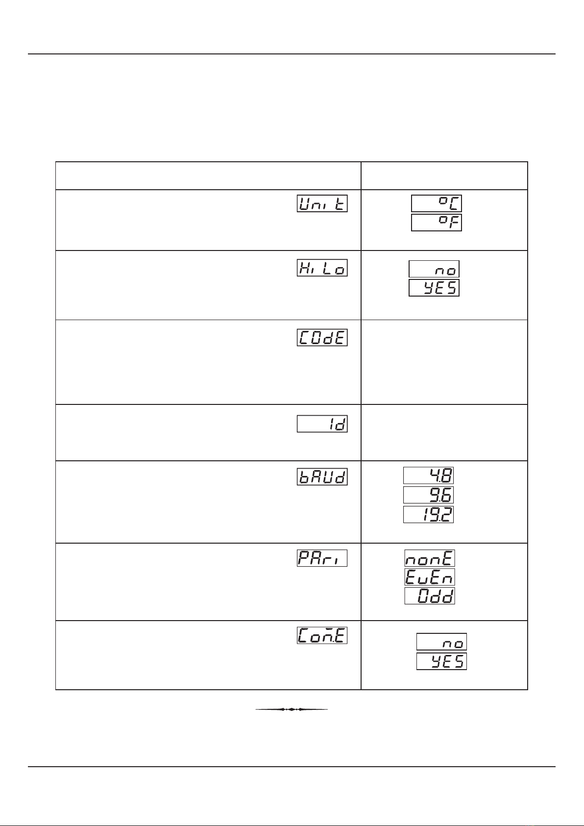
PAGE-13 : SUPERVISORY PARAMETERS
Table 7.1
PASSWORD FOR RESETTING
PV HIGH - LOW
This parameter allows protection against inadvertent resetting of
Min/Max values. That is, the reset command is executed only if the
operator sets the password that matches with this parameter
value.
Set this parameter value to ‘Yes’ for enabling the Dry-Bulb
Temperature and % RH monitoring for Min/Max values.
DRY-BULB TEMPERATURE AND
% RH MIN / MAX MONITORING
UNIT SELECTION FOR TEMPERATURE
Select Temperature Units in °C or °F.
Parameter Description Settings
(Default Value)
°C
°F
(Default : )°C
(Default : 0)
0 to 250
(Default : No)
No
Yes
Section 7
Yes
No
(Default : Yes)
BAUD RATE
Communication speed in ‘Bits per Second’. Set the value to match
with the host baud rate.
(Default : 1)
1 to 127
Communication ID used by host for serial communication.
SLAVE ID
Parity setting for serial communication protocol
PARITY
Setting to ‘No’ disallows the host to set or modify any parameter
values. The parameter values however, are still available for
reading by the host.
COMMUNICATION WRITE ENABLE
(Default : 9600)
4800
9600
19200
(Default : Even)
None
Even
Odd

User Manual
HumiTherm-i Pro
14
PAGE-14 : DE-HUMIDIFIER CONTROL PARAMETERS
Table 8.1
Parameter Description Settings
(Default Value)
Section 8
(Default : Disable)
Disable
Enable
(Default : 0)
0.0 to 100.0
(Default : 2.0)
0.1 to 99.9
DE-HUMIDIFIER CONTROL
Set this parameter to Enable if Humidifier Control is desired. If
enabled, the measured %RH value is compared with the set value
and a relay output is switched.
DE-HUMIDIFIER SETPOINT
If the measured %RH value becomes equal or exceed this
setpoint value, the de-humidifier control output relay is switched-
On.
De-humidifier ON condition :
%RH >= De-humidifier Setpoint
DE-HUMIDIFIER HYSTERESIS
If the measured %RH value becomes equal or falls below the
setpoint minus hysteresis, the de-humidifier control output relay is
switched- Off.
De-humidifier OFF condition :
%RH <= (De-humidifier Setpoint - De-humidifier Hysteresis)
User Manual
HumiTherm-i Pro
15
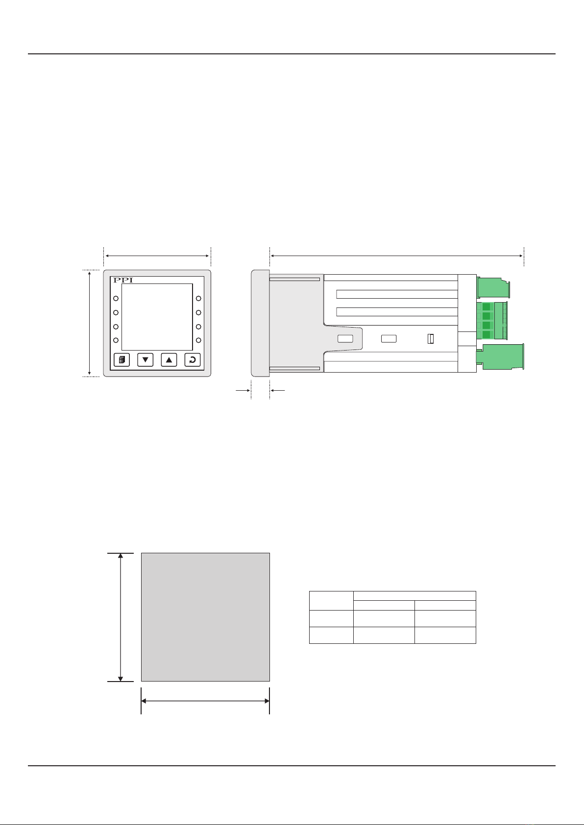
MECHANICAL INSTALLATION
Section 9
OUTER DIMENSIONS AND PANEL CUTOUT
The Figure 9.1 shows the controller outer dimensions.
Figure 9.1
Figure 9.2
94mm
(3.70in)
7mm (0.276in)
Side View
48mm
(1.89in)
48mm
(1.89in)
Front View
°CA
RHA
L1
DHO
L3
HumiTherm-i Pro
L2
COM L4
PANEL CUTOUT
The Figure 9.2 shows the panel cutout requirements for a single controller.
V
H
Parameter Dimensions
mm inches
H
V
45 (-0, +0.5)
45 (-0, +0.5)
1.77 (-0, +0.02)
1.77 (-0, +0.02)
User Manual
HumiTherm-i Pro
16
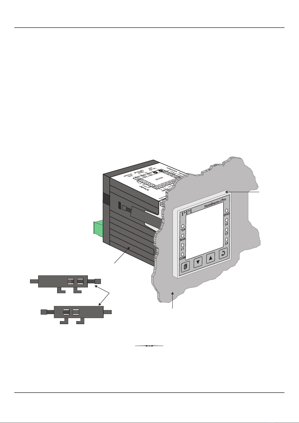
PANEL MOUNTING
Follow the steps below for mounting the controller on panel:
1. Prepare a square cutout to the size shown in Figure 9.2.
2. Remove the Panel Mounting Clamp from the controller Enclosure and insert the rear of the controller housing through the
panel cutout from the front of the mounting panel.
3. Hold the controller gently against the mounting panel such that it positions squarely against the panel wall, see Figure 9.3.
Apply pressure only on the bezel and not on the front label.
4. Insert the mounting clamps on either side of the controller in the slots provided for the purpose. Rotate the screws clock-
wise so that they move forward until they push firmly against the rear face of the mounting panel for secured mounting.
Figure 9.3
Clamps
Bezel
Controller
Mounting Panel with
Square Cutout

User Manual
HumiTherm-i Pro
17
ELECTRICAL CONNECTIONS
WARNING
MISHANDLING / NEGLIGENCE CAN
RESULT IN PERSONAL DEATH OR
SERIOUS INJURY.
Figure 10.1
Section 10
1 2 345
21
20
19
18
10
1112
13
14
1516
17
6
7
8
9
+
-
L N
NO C
EXC
5/12/24V
85~264
VAC
Relay
DE-HUM
B+ B-
RS485
TEMP INPUT
+
RTD
RH INPUT
mA/V
-
+
RTD
TEMP. ALARM
RH ALARM
NOCNC
RLY
+
-
SSR
NOCNC
RLY
SSR
mA/V
-
+
1. The user must rigidly observe the Local Electrical Regulations.
2. Do not make any connections to the unused terminals for making a tie-point for other wires (or for any other reasons) as
they may have some internal connections. Failing to observe this may result in permanent damage to the controller.
3. Run power supply cables separated from the low-level signal cables (like RTD, DC Linear (Voltage) signals, etc.). If the
cables are run through conduits, use separate conduits for power supply cable and low-level signal cables.
4. Use appropriate fuses and switches, wherever necessary, for driving the high voltage loads to protect the controller from
any possible damage due to high voltage surges of extended duration or short-circuits on loads.
5. Take care not to over-tighten the terminal screws while making connections.
6. Make sure that the controller supply is switched-off while making/removing any connections or removing the controller
from its enclosure.
CONNECTION DIAGRAM
The Electrical Connection Diagram is shown on the top side of the enclosure. The diagram shows the terminals viewed from
the REAR SIDE with the controller label upright. The connecters provided for wiring are pluggable male-female type. The
female parts are soldered on the controller PCBs while the male parts are with screws and removable. The rear panel
electrical wiring connection diagram is shown in Figure10.1.
User Manual
HumiTherm-i Pro
18
DESCRIPTIONS
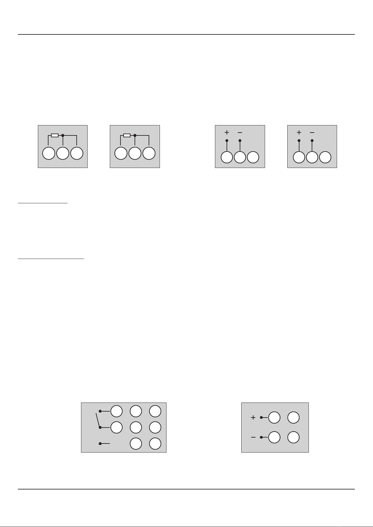
TEMP INPUT : RTD Pt100, 3-Wire / mA / V (Terminals 17, 16, 15)
RH INPUT : RTD Pt100, 3-Wire / mA / V (Terminals 14, 13, 12)
RTD Pt100, 3-wire
Connect single leaded end of RTD bulb to terminal 17 (14) and the double leaded ends to terminal 16 (13) and 15 (12),
interchangeable, as shown in Figure 10.2 (a). Use copper conductor leads of very low resistance ensuring that all 3 leads are
of the same gauge and length. Avoid joints in the cable.
DC Linear Signal (mA/V)
Use a shielded twisted pair with the shield grounded at the signal source for connecting Voltage source. Connect common (-)
to terminal 16 (13) and the signal (+) to terminal 17 (14), as shown in Figure 10.2 (b).The DC Current source (mA) is also
connected in the similar way.
TEMP. ALARM : Relay (Terminals 18, 19, 20)
TEMP. ALARM : SSR (Terminals 18, 19)
RH ALARM : Relay (Terminals 7, 8, 9)
RH ALARM : SSR (Terminals 8, 9)
DE-HUM CONTROL OUTPUT : Relay (Terminals 3, 4)
Figure 10.2 (a) : RTD Input
1516
17
Temperature Input
1213
14
Humidity Input
Figure 10.2 (b) : mA / V Input
1516
17
Temperature Input Humidity Input
1213
14
Figure 10.3
NO
C
NC
9
8
7
3
4
18
19
20
Temp. Alarm / RH Alarm / De-hum Control
Relay
9
8
18
19
Temp. Alarm / RH Alarm
SSR
Table of contents
Other PPI Measuring Instrument manuals


