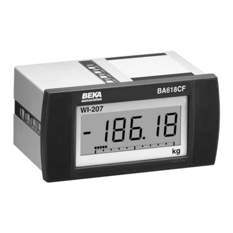
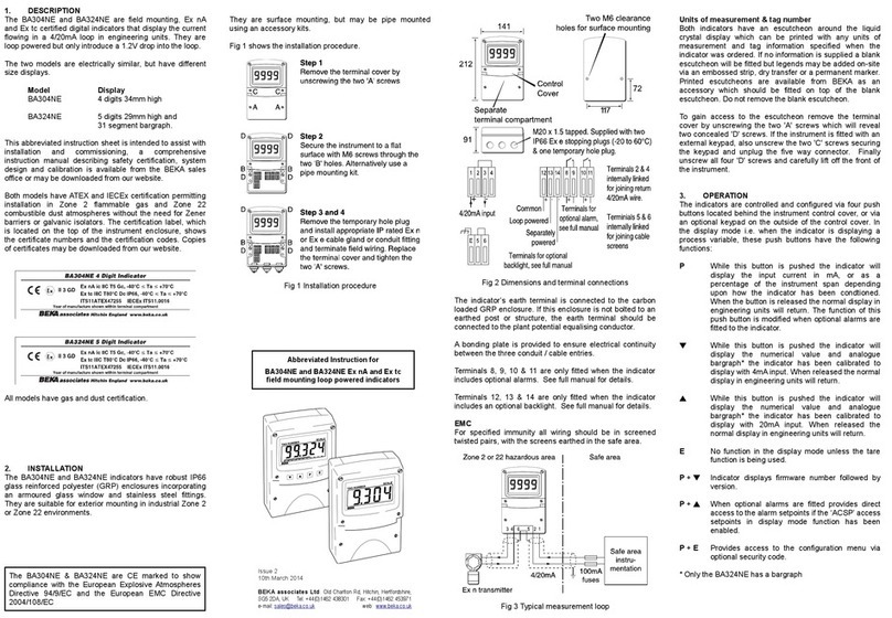
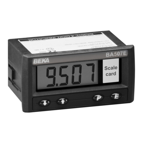
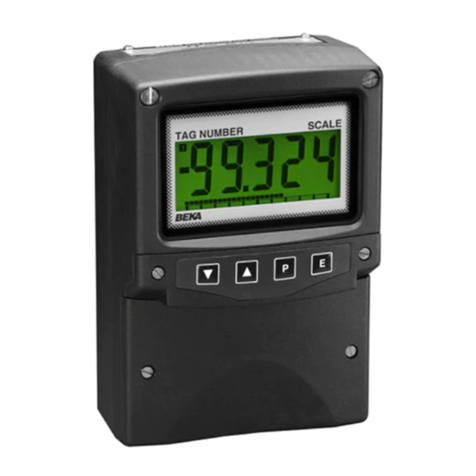
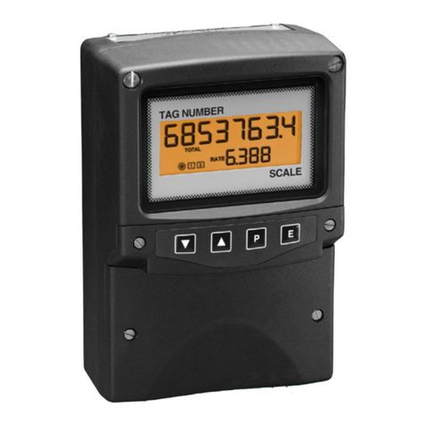
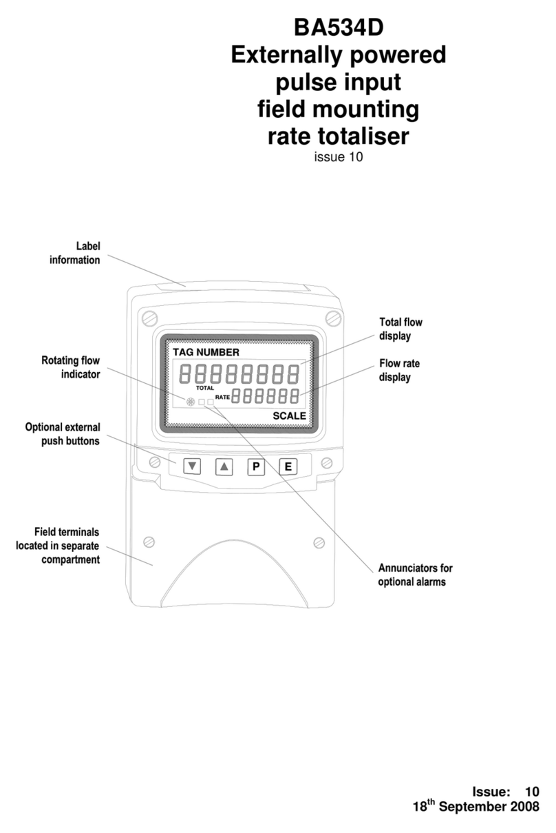
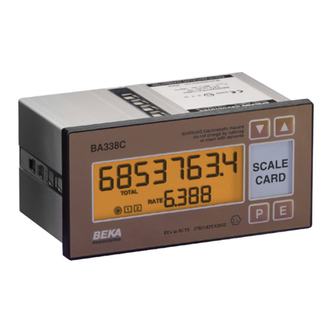
BEKA BA558E User manual

Issue: 3
4th July 2014
BA558E
General Purpose
4/20mA loop-powered
panel mounting
Rate Totaliser
Issue 3

1. Description
2. Operation
2.1 Controls
2.2 Displays
3. Applications
3.1 Flow transmitter loops
3.2 Resetting the total display to zero
3.3 Remote indication
4. Installation
4.1 Location
4.2 EMC
4.3 Installation procedure
4.4 Scale card
5. Configuration and Calibration
5.1 Calibration structure
5.2 Accessing configuration & calibration
functions.
5.3 Summary of configuration
functions.
5.4 Rate totaliser function
5.5 Display resolution
5.6 Display update time
5.7 Upper display
5.8 Lower display
5.9 Position of decimal points
5.10 Calibration of rate display using an
external current source.
5.11 Calibration of rate display using internal
reference.
5.12 Clear grand total
5.13 Timebase
5.14 Function of Ppush button
5.15 Total scale factor
5.16 Clip off
5.17 Local reset of total & grand total
displays.
5.18 Security code
5.19 Reset to factory defaults
5.20 Over-range
6. Lineariser
6.1 Calibration using external current
source.
6.1.1 Example, Adding break-points
to a new Rate Totaliser
6.2 Calibration using internal reference
6.2.1 Example, Adding break-points
to a new Rate Totaliser
6.3 Error messages
6.4 Under and over-range
6.5 Default configuration
7. Calibration Examples
7.1 Using an external current source
7.2 Using the internal reference
8. Maintenance
8.1 Fault finding during commissioning
8.2 Fault finding after commissioning
8.3 Servicing
8.4 Routine maintenance
8.5 Guarantee
8.6 Customer comments
9.Accessories
9.1 Scale card
9.2 Tag information
9.3 Alarms
9.3.1 Solid state output
9.3.2 Configuration and adjustment
9.3.3 Alarm enable
9.3.4 Type of alarm
9.3.5 Setpoint adjustment
9.3.6 Alarm function
9.3.7 Alarm output status
9.3.8 Hysteresis
9.3.9 Alarm delay
9.3.10 Alarm silence time
9.3.11 Flash display when alarm
occurs.
9.3.12 Access setpoint
9.3.13 Adjusting alarm setpoints
from display mode.
9.4 Display backlight
9.4.1 Loop powered
9.4.2 Separately powered
22
CONTENTS
The BA558E is CE marked to show compliance with the European EMC Directive 2004/108/EC

1. DESCRIPTION
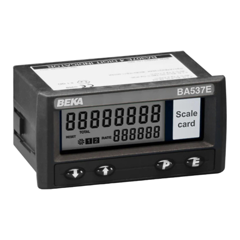
The BA558E is a panel mounting general purpose
4/20mA loop-powered Rate Totaliser primarily
intended for use with flowmeters. The instrument
simultaneously displays the rate of flow and the
total flow in engineering units on two separate
displays. The BA558E only introduces a 1.2V
drop, which allows it to be installed into almost any
4/20mA flow loop. No additional power supply or
battery is required.
2. OPERATION
Fig 1 shows a simplified block diagram of a
BA558E. The 4/20mA input current flows through
resistor R1 and forward biased diode D1. The
voltage developed across D1, which is relatively
constant, is multiplied by a switch mode power
supply and used to power the instrument. The
voltage developed across R1, which is proportional
to the 4/20mA input current, provides the input
signal for the analogue to digital converter.
Each time a 4/20mA current is applied to the
instrument, initialisation is performed. After a short
delay the following display sequence occurs which
takes about twelve seconds:
All segments of the display are activated
Loading message displayed
Configuration message displayed
Model and firmware version displayed
The BA558E Rate Totaliser starts
functioning, using configuration information
stored in the instrument’s permanent
memory. Unless total and grand total
displays have been reset to zero, new flow
will be added to the existing totals.
If the 4/20mA current is disconnected during
operation the latest total and grand total are stored
in permanent memory.
Fig 1 Simplified block diagram of BA558E
2.1 Controls
The BA558E is controlled and calibrated via four
front panel push buttons located below the display.
In the operating mode i.e. when the instrument is
displaying rate and total flow the push button
functions are:
Summary of Push Button Functions
PDisplays input current in mA or as a
percentage of span. Modified when
optional alarms are fitted.
▼Shows rate display calibration at 4mA
input.
▲Shows rate display calibration at
20mA input.
EShows time since instrument was
powered or total display was reset.
E+▼Grand total –
displays least significant 8 digits
E+▲Grand total –
displays most significant 8 digits.
▼+▲Resets total display
configurable function.
P+▼Shows firmware version
P+▲Alarm setpoint access
P+E Access to configuration menu
configurable function,
3

Full Description of Push Button Functions
PWhile this button is pushed the rate
display will show the input current in
mA, or as a percentage of the
instrument span depending upon how
the instrument has been configured.
When the button is released the normal
display in engineering units will return.
The function of this push button is
modified when optional alarms are fitted
to the instrument.
▼While this button is pushed the
instrument will show the calibrated rate
display with 4mA*input - usually zero
for flow applications. When the button
is released the flow rate will again be
displayed.
▲While this button is pushed the
instrument will show the calibrated rate
display with 20mA*input. When the
button is released the flow rate will
again be displayed.
EWhile this button is pushed the Rate
Totaliser will display the time in hours,
minutes and seconds since the
instrument was powered or the total
display was reset. The elapsed time is
not saved when power is removed.
E+▼While these buttons are pushed the
total display will show the least
significant eight digits of the grand total,
and the grand total annunciator will be
activated.
E+▲While these two buttons are pushed the
total display will show the most
significant eight digits of the grand total
and the grand total annunciator will be
activated.
After the two buttons have been pushed
for ten seconds ‘CLr no’ with the ‘no’
flashing will be displayed. If no action
is required, pressing Ewill return the
instrument to the operating mode.
Operating the ▼or ▲button will toggle
the display to ‘CLr YE5’ with ‘YE5’
flashing, operating the E button will then
clear the grand total and ‘Gt CLrd’ will
be displayed to confirm the operation.
The instrument will then automatically
return to the operating mode.
Selectable function in the configuration
menu. See section 5.17
Note: Totalisation will continue until
‘CLr no’ or ‘CLr YE5’ are displayed.
▼+▲Resets the total display to zero
when these two push buttons are
operated simultaneously. Selectable
function in the configuration menu.
See section 5.17
P+E Provides access to the configuration
menu via optional security code.
Note: *If the Rate Totaliser has been
calibrated using the CAL function,
calibration points may not be 4 and
20mA.
2.2 Displays
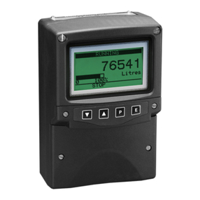
The BA558E has two digital displays and
associated annunciators, plus a flow indicator as
shown on page 1.
Upper Shows the flow rate on the five digit
display plus sign 12mm high display.
Lower Shows the total flow on the eight digit
display (seven with negative sign) 18mm high
display which may be reset to zero by
operating the ▼+ ▲instrument push
buttons or by an external contact
closure.
The rate and total displays may be interchanged,
see section 6.7
Flow This disc on the lower left hand
indicator side of the display rotates when the
input current exceeds 4.000mA,
indicating that flow is being detected by
the Rate Totaliser. For bi-directional
flow, the disc rotates when flow
exceeds ±0.05% of span.
Annunciators
Reset Activated when total display is reset to
zero by operating the ▼+ ▲buttons
simultaneously or by connecting the
reset terminals together.
Hold Activated when flow rate falls below the
clip-off value and totalisation is
inhibited.
4
3. APPLICATIONS
3.1 Flow transmitter loops
A BA558E Rate Totaliser may be connected in
series with almost any 4/20mA flow loop and
calibrated to display the rate of flow and total flow.
Fig 2 illustrates a typical applications in which a
BA558E Rate Totaliser is connected in series with
a 2-wire flow transmitter.
Fig 2 Typical flow loop
3.2 Resetting the total display to zero
The BA558E total display may be reset to zero by
momentarily connecting the reset terminals RS1
and RS2 together with a resistance of less than
1kΩas shown in Fig 2.
Note:
The negative reset terminal RS2 is internally
connected to the negative 4/20mA input
terminal 3.
The total display may also be reset to zero by
operating the totalisers ▲and ▼push buttons
simultaneously for more than two seconds. See
section 5.17
3.3 Remote flow indication
A BA558E may be driven from any 4/20mA signal
to provide a remote indication of rate and total flow.
Again it is necessary to ensure that the voltage
capability of the 4/20mA signal is sufficient to drive
the Rate Totaliser which requires 1.2V rising to 5V
if the optional backlight is loop powered.
Fig 3 shows a typical application.
Fig 3 BA558E providing remote display
of rate & total flow.
5

4. INSTALLATION
4.1 Location
The BA558E has a robust glass reinforced
modified PPO enclosure with a toughened glass
window. The front of the Rate Totaliser has IP66
protection and a gasket seals the joint between the
instrument enclosure and the panel. The rear of
the instrument has IP20 protection.
The BA558E will function at ambient temperatures
between –40ºC and +70ºC, but the display only
functions at ambient temperatures between –20ºC
and +70ºC,
Fig 4 shows the overall BA558E Rate Totaliser
dimensions together with the recommended panel
cut-out dimensions. To achieve an IP66 seal
between the instrument enclosure and the
instrument panel the smaller tolerance aperture
must be used, and the Rate Totaliser must be
secured with four panel mounting clamps.
Although the Rate Totaliser front panel provides
IP66 protection it should be shielded from direct
sunlight and severe weather conditions.
Fig 4 BA558E dimensions
4.2 EMC
The BA558E Rate Totaliser complies with the
requirements of the European EMC Directive
2004/108/EC. For specified immunity all wiring
should be in screened twisted pairs, with the
screens earthed at one point.
4.3 Installation Procedure
a. Cut the specified aperture in the panel. To
achieve an IP66 seal between the instrument
enclosure and the instrument panel the
aperture must have the tighter tolerances
specified in Fig 4.
b. Slide the gasket over the body of the Rate
Totaliser before inserting the instrument into
the panel aperture.
c. Firstly ensure that all the panel mounting
clamps are closed by turning the knurled
screws fully anti clockwise until the two pips
in the clamp foot align with holes in the clamp
body.
d. Place a clamp in the recess on each side of
the Rate Totaliser, pulling gently to slide it
onto the dovetail as shown in Fig 5. Push
the knurled screw slightly forward to engage
the thread and tighten by turning clockwise
until it is just finger tight. When all four
clamps are fitted ensure that the gasket
behind the front panel bezel is correctly
positioned before fully tightening the clamps
to secure the instrument. The maximum
recommended clamp tightening torque is
22cNm (1.95 lbf in) which is approximately
equivalent to finger-tight plus one half turn.
Do not over tighten.
e. Connect the panel wiring to the rear terminal
block(s) as shown in Figs 4. To simplify
installation, the terminals are removable so
that the panel wiring can be completed
before the instrument is installed.
Fig 5 Fitting panel mounting clamps
6

4.4 Scale card
The Rate Totaliser’s units of measurement are
shown on a printed scale card in a window at the
right hand side of the display. The scale card is
mounted on a flexible strip that is inserted into a
slot at the rear of the instrument as shown in Fig 6.
Thus the scale card can easily be changed without
removing the BA558E Rate Totaliser from the
panel or opening the instrument enclosure.
New instruments are supplied with a printed scale
card showing the requested units of measurement,
if this information is not supplied when the Rate
Totaliser is ordered a blank card will be fitted.
A pack of self-adhesive scale cards printed with
common units of measurement is available as an
accessory from BEKA associates. Custom printed
scale cards can also be supplied.
To change a scale card, unclip the protruding end
of the flexible strip by gently pushing it upwards
and pulling it out of the enclosure. Peel the
existing scale card from the flexible strip and
replace it with a new printed card, which should be
aligned as shown below. Do not fit a new scale
card on top of an existing card.
Install the new scale card by gently pushing the
flexible strip into the slot at the rear of the
instrument, when it reaches the internal end-stop
secure it by pushing the end of the flexible strip
downwards so that the tapered section is held by
the rear panel.
Align the self-adhesive
printed scale card onto the
flexible strip and insert the
strip into the Rate
Totaliser as shown below.
Fig 6 Inserting flexible strip carrying scale card
into slot at the rear of Rate Totaliser.
7

5. CONFIGURATION AND CALIBRATION
The BA558E is configured and calibrated via the
four front panel push buttons that are located
below the display.
All the configuration functions are contained in an
easy to use menu that is shown diagrammatically
in Fig 8. Each function is summarised in section
5.3 which includes references to more detailed
information. Although this simple menu driven
system enables most adjustments to be made
without repeated reference to this manual, it is
recommended that at least the summary of the
configurable functions in section 5.3 is read before
attempting configuration or recalibration.
When the instrument is fitted with alarms, the basic
menu is expanded to include the alarm functions
that are described in section 9.3 of this manual.
Note:
While the instrument is being configured or
calibrated totalisation is suspended, any flow
occurring during this time will not be
recorded.
5.1 Calibration structure
Fig 7 shows the BA558E calibration structure. The
4/20mA input current, which in flow applications
represents flow rate, is usually displayed on the six
digit plus sign rate display. If necessary this flow
signal may be linearised using the square root
extractor or the 16 segment lineariser which are
selectable in the instrument’s ‘FunC’ block. The
rate display may then be calibrated using the
'CAL' or 'SEt' functions to show the flow rate in the
required linear engineering units. Both the zero
(display at 4mA) and the span (display at 20mA)
are adjustable, although for flow application the
display at 4mA is usually zero. The position of
the decimal point in the rate display is defined by
the ‘dP’ function. To simplify calibration the
BA558E uses floating point arithmetic, moving the
rate display decimal point position will therefore
affect totalisation.
For bi-directional flow applications zero flow will be
represented by an input current other than 4mA.
When one of the two bi-direction functions in the
‘FunC’ sub-menu is selected, input currents below
that representing zero flow will be shown as a
negative flow rate and the total flow display will
count down. For input currents above that
representing zero flow will be shown as a positive
flow rate and the total flow display will count up.
The BA558E total display is calculated from the
rate display using two serial factors: the timebase
't-bA5E' and the total scaling factor '5CALE-t'. The
timebase divides the rate display according to
whether the rate display represents flow per
second, per minute or per hour. The total scaling
factor '5CALE-t' is a wide range configurable
dividing factor allowing the rate and total displays
to be in different units.
For example, if a BA558E is displaying rate in litres
per minute, setting '5CALE-t' to 4.5461 produces a
total display in UK gallons. Alternatively, setting
'5CALE-t' to 4546.1 will produce a total display in
thousands of UK gallons.
The total is calculated and the display updated
once per second, which defines the resolution of
the total flow display. When total alarms are used
for batching applications, this resolution may define
the accuracy of the system.
Fig 7 Calibration structure
8

5.2 Accessing the configuration and
calibrations functions.
Throughout this manual push buttons are shown
as P, E,▼or ▲, and legends displayed by the
Rate Totaliser are shown within inverted commas
e.g. 'CAL' and ' ALr2'.
Access to the configuration menu is obtained by
operating the Pand Epush buttons
simultaneously. If the Rate Totaliser’s security
code is set to the default 0000 the first parameter
'FunC' will be displayed. If a security code other
than the default code 0000 has already been
entered, the Rate Totaliser will display 'CodE'.
Pressing the Pbutton will clear this prompt
allowing each digit of the code to be entered using
the ▲and ▼push buttons and the Pbutton to
move control to the next digit. When the correct
four digit code has been entered pressing Ewill
cause the first parameter 'FunC' to be displayed.
If the code is incorrect, or a button is not pressed
within twenty seconds, the Rate Totaliser will
automatically return to the display mode.
Once within the configuration menu the required
parameter can be reached by scrolling through the
menu using the ▲and ▼push buttons as shown
in Fig 8. When returning to the display mode
following recalibration or a change to any function,
the Rate Totaliser will display ‘dAtA’ followed by
‘SAVE’ while the new information is stored in non-
volatile memory.
All new Rate Totalisers are supplied calibrated as
requested at the time of ordering. If calibration is
not requested, Rate Totalisers will be supplied with
the following default configuration:
Default Configuration
Access code ‘CodE’ 0000
Function ‘FunC’ ‘5td’ Linear
Rate display at 4mA ‘Zero’ 0.00
Rate display at 20mA ‘5PAn’ 100.00
Resolution ‘rE5n’ 1 digit
Pbutton in display mode ‘C—P’ %
Local reset of total ‘t-rE5Et’ off
Local reset of grand total ‘Gt-rE5Et’ off
Clip off ‘CLIP oFF’ 000.00
Timebase ‘t-bA5E’ 1
Total scale factor ‘5CALE-t’ 1.00
Upper display ‘di5P-1’ Total
Update time ‘uPdAtE’ 1
5.3 Summary of configuration functions
This section summarises each of the main
configuration functions and includes a cross
reference to a more detailed description. Fig 8
illustrates the location of each function within the
configuration menu. The lineariser and the
optional factory fitted alarms are described
separately in sections 6 and 9.3 of this manual.
Display Summary of function
'FunC' Rate Totaliser function
Defines the relationship between the
4/20mA input current and the
instruments rate display.
For uni-directional flow may be set
to:
‘5td’ Standard linear relationship
‘root’ Square root extraction
‘Lin’ 16 segment adjustable
lineariser – see section 6
For bi-directional flow may be set
to:
‘bi-5td’ Standard linear relationship
‘bi-Lin’ 16 segment adjustable
lineariser – see section 6
See section 5.4
'rE5n' Display resolution
Defines the resolution of the least
significant rate display digit. May be
set to ‘1’, ‘2’, ‘5’ or ‘10’ digits.
See section 5.5
‘uPdAtE’ Update
Defines the interval between
updates. May be set to ‘1’, ‘2’, ‘3’,
‘4’ or ‘5’ seconds.
See section 5.6
‘di5P-1’ Upper display
Defines whether ‘totAL’ or ‘rAtE’ is
shown on the upper eight digit
display.
See section 5.7
‘di5P-2’ Lower display
Turns lower six digit display ‘on’ or
‘oFF’.
See section 5.8
'dP' Decimal points
Positions the decimal point in the
‘rAtE’ and ‘totAL’ displays.
See section 5.9
9

Display Summary of function
'CAL' Calibration of the rate display
using an external current source.
Enables the zero and span of the
rate display to be adjusted using an
external current source such as a
calibrator. When used with an
accurate traceable calibrator this is
the preferred method of calibration.
See section 510
'5Et' Calibration of rate display using
internal references.
Enables the zero and span of the
rate display to be adjusted without
the need for an accurate input
current or disconnection from the
4/20mA loop.
See section 5.11
‘Clr.Gtot’ Clear grand total
Resets the sixteen digit grand total
to zero when ‘Clr.YES’ is selected
and ‘5urE’ is entered digit by digit to
confirm the instruction.
Note: Once cleared a grand total
can not be recovered.
See section 5.12
‘t-bA5E’ Timebase
Selectable divisor to display flow
rate in units per second, per minute
or per hour.
Select:
‘tb-01’ for flow / second
‘tb-60’ for flow / minute
‘tb-3600’ for flow / hour
See section 5.13
'C - - P' Function of P push button
The Rate Totaliser may be
configured to display the input
current in milliamps, or the input
current as a percentage of the
4/20mA input when the Ppush
button is operated in the display
mode.
Select:
‘PC’ % of 4/20mA input
‘4-20’ Current in mA
Note: ‘PC’ is not available with
lineariser.
See section 5.14
Display Summary of function
‘5CALE-t’ Total scale factor
Defines the arithmetic relationship
between the rate and total displays.
May be adjusted between 0.0001
and 99999
5CALE-t = Units of rate display
Units of total display
To calculate 5CALE-t the required
units of measurement for the total
display must be converted to the
units of measurement used for the
rate display.
See section 5.15 and Fig 6.
'CLiP-oFF' Clip off
To prevent the totalisation of very
low flow rates, this function defines
the flow rate below which totalisation
is inhibited and the ‘HOLD’
annunciator activated.
See section 5.16
'LoC.r5Et' Local reset of total and grand
total.
Contains two independent functions
‘t-rE5et’ and ‘Gt-rE5Et’.
‘t-rE5Et’ enables the total display to
be reset to zero when ▼and ▲
push buttons are operated
simultaneously for more than 2
seconds.
‘Gt-rE5Et’ enables the grand total to
be reset to zero when Eand ▲push
buttons are operated simultaneously
for more than 10 seconds.
See section 5.17
'CodE' Security code
Defines a four digit numeric code
that must be entered to gain access
to the configuration menu. Default
code 0000 disables this security
function and allows unrestricted
access to all conditioning functions.
See section 5.18
10

Display Summary of function
'r5Et' Reset Rate Totaliser to factory
defaults.
Contains two sub-functions,
Select:
‘ConF’ Returns instrument to
default configuration
shown in section 5.2
‘LtAb’ Returns lineariser to
defaults shown in
section 6.5
Both instructions must be confirmed
by entering ‘5urE’ digit by digit
before they will be executed.
See section 5.19
11

12

5.4 Rate Totaliser function: ‘FunC’
This configuration function defines the relationship
between the Rate Totaliser’s 4/20mA input current
and the instruments’s rate display. Three
alternatives are available for uni-direction flow and
two for bi-direction flow.
For uni-directional flow:
‘5td’ Standard linear relationship
‘root’ Square root extraction
‘Lin’ 16 segment adjustable lineariser
For bi-directional flow:
‘bi-5td’ Standard linear relationship
‘bi-Lin’ 16 segment adjustable lineariser
To reveal the existing instrument function select
'FunC' from the configuration menu and press P.
If the function is set as required, press Eto return
to the menu, or press the ▲or ▼button to change
the setting, followed by the Ebutton to return to the
configuration menu.
‘5td’ Linear
Provides a linear relationship between the
4/20mA Rate Totaliser input current and
the instruments rate display for
uni-directional flow.
‘root’ Square root extraction
Primarily intended to linearise the square
law 4/20mA output from differential
flowmeters.
For reference, the following table shows
the output current from a non-linearised
differential flowmeter.
% of full flow Current output mA
2.5 4.01
10.0 4.16
25.0 5.00
50.0 8.00
75.0 13.00
100.0 20.00
When the root function is selected the Rate
Totaliser will display flow in linear units for
uni-directional flow.
‘Lin’ 16 segment adjustable lineariser
May be adjusted to compensate for
flowmeter non-linearity with uni-directional
flow. Use of the lineariser is described in
section 6 of this instruction manual.
‘bi-5td’ Linear
Provides a linear relationship between the
4/20mA Rate Totaliser input current and
the instruments rate display for
bi-directional flow.
‘bi-Lin’ 16 segment adjustable lineariser
May be adjusted to compensate for
flowmeter non-linearity with bi-directional
flow. Use of the lineariser is described in
section 6 of this instruction manual.
5.5 Display resolution: ‘rE5n’
This function defines the resolution of the least
significant display digit of the rate display.
Decreasing the display resolution can improve the
readability of a noisy signal. Select ''rE5n' from
the menu and press Pwhich will reveal the current
display resolution. To change the resolution press
the ▲or ▼button to select 1, 2, 5 or 10 digits,
followed by the Ebutton to enter the selection and
return to the configuration menu.
5.6 Display update time: ‘uPdAtE’
If the rate display is likely to change rapidly,
extending the time between display updates will
make the display easier to read. Five different
intervals between readings are selectable, 1, 2, 3,
4 or 5 seconds.
To reveal the existing update time select 'uPdAtE'
from the configuration menu and press P. If the
time is set as required, press Eto return to the
menu, or press the ▲or ▼button to change the
time, followed by the Ebutton to return to the
configuration menu.
This function only changes the interval between
successive display updates, it does not change the
instrument accuracy.
5.7 Upper display: ‘di5P-1’
The Rate Totaliser has two numeric displays:
Upper
8 digit 18mm high intended for showing total flow
display range –9999999 to 99999999
Lower
6 digits 12mm high intended for showing flow rate
display range –99999 to 99999
This function interchanges the rate and total
displays when the flow rate is required to be
predominant, resulting in a 5 digit plus sign upper
rate display and a 6 digit lower total display, or 5
digits plus sign when negative.
To reveal the existing upper display function select
'di5P-1' from the configuration menu and press P.
If set as required, press Eto return to the
configuration menu, or press the ▲or ▼button to
toggle the function between ‘totAL’ and ‘rAtE’.
When set as required press Eto enter the
selection and to return to the configuration menu.
13

5.8 Lower display: ‘di5P-2’
When only one display is required this function
allows the lower display to be disabled. To reveal
if the lower display is activated select 'di5P-2' from
the configuration menu and press P. If set as
required, press Eto return to the configuration
menu, or press the ▲or ▼button to toggle the
function between ‘on’ and ‘oFF’. When set as
required press Eto enter the selection and to
return to the configuration menu.
5.9 Position of the decimal points: ‘dP’
This function defines the position of the decimal
point in both the rate and total displays.
Rate display
The rate display can have up to five digits plus
sign, the decimal point may be positioned
between any of the digits, or may be omitted.
The BA558E uses floating point arithmetic so
moving the position of the rate display decimal
point will affect totalisation.
Total display
The total display can have up to eight digits or
seven digits with a negative sign, the decimal
point may be positioned with up to five digits
after it, or it may be omitted.
Notes:
a. The position of the decimal point in the
Grand Total will be the same as that
selected for the Total Display.
b. If the total display decimal point can’t be
moved to the left it is likely that the existing
display will be over-ranged by the
adjustment. The total display should be
reset to zero, which should allow the decimal
point to be positioned as required.
c. If the decimal point is moved to the right, the
existing total display will be truncated, not
rounded, the lost precision can not be
recovered.
Positioning the decimal points
To adjust the position of either the rate or total
display decimal point select 'dP' from the
configuration menu and press P. The upper
display defined as the rate or total display by
function ‘di5P-1’ (section 5.7) will be activated
and identified. The decimal point can be
positioned by operating the ▼or ▲push
button, when set as required enter the setting
and return to the conditioning menu by
operating the Ebutton. Alternatively, to position
the lower display decimal point press the P
button which will display and identify the lower
display variable, but on the larger upper display.
The position of the decimal point can be
positioned in the same way by operating the ▼
and ▲push buttons, when set as required
enter the setting and return to the conditioning
menu by operating the Ebutton.
5.10 Calibration of the rate display using an
external current source: ‘CAL’
This function enables the zero and span of the rate
display to be adjusted using an external calibrated
current source. When used with an accurate
traceable current source this is the preferred
method of calibration.
Zero rate display with 4mA input
Span rate display with 20mA input
To calibrate the rate display select 'CAL' from the
configuration menu and press P.The BA558E will
display 'ZEro' which is a request for a 4mA input
current. Adjust the external current calibrator to
4.000mA and again press Pwhich will reveal the
current zero rate display. The flashing digit of the
display can be changed by pressing the ▲or ▼
buttons, when set as required pressing Pwill
transfer control to the next digit. When all the
digits have been adjusted, press Eto enter the
new zero and return to the 'ZEro' prompt .
Pressing the ▲button will cause the BA558E to
display '5PAn' which is a request for a 20mA input
current. Adjust the external current calibrator to
20.000mA and again press Pwhich will reveal the
existing span rate display. The flashing digit of the
display can be changed by pressing the ▲or ▼
buttons, when set as required pressing Pwill
transfer control to the next digit. When all the
digits have been adjusted press Eto enter the new
rate span and return to the '5PAn' prompt. Finally
press Eagain to return to the configuration menu.
Notes:
a. The Rate Totaliser input current must be
adjusted to the required value before the zero
and span functions are entered by pressing the
P button.
b. Rate Totalisers may be calibrated at currents
other than 4 and 20mA, within the range 3.8 to
21.0mA providing the difference between the
two currents is greater than 4mA. If these
conditions are not complied with, the
instrument displays ‘FaiL’ and aborts the
calibration.
c. If the zero current is greater than the span
current the instrument will be reverse acting
i.e. an increasing input current will cause the
display to decrease.
14

5.11 Calibration of the rate display using
internal reference: ‘5Et’
Using the ‘5Et’ function the rate display can be
calibrated without the need to know the value of
the 4/20mA input current, or to disconnect the
BA558E Rate Totaliser from the 4/20mA loop.
When using the ‘5Et’ function the instrument’s
internal reference is used to simulate a 4mA and
20mA input current.
Zero rate display with a simulated 4mA input
Span rate display with a simulated 20mA input
To calibrate the rate display select '5Et' from the
configuration menu and press P. The Rate
Totaliser will display 'ZEro', pressing Pagain will
reveal the current rate display at 4mA. The
flashing digit can be adjusted by pressing the ▲or
▼buttons, when set as required pressing Pwill
transfer control to the next digit. When all the
digits have been adjusted, press Eto return to the
'ZEro' prompt.
To adjust the rate display at 20mA, press the ▲
button which will cause the Rate Totaliser to
display '5PAn', pressing Pwill then reveal the
existing rate display at 20mA. The flashing digit
can be adjusted by pressing the ▲or ▼buttons,
when set as required pressing Pwill transfer
control to the next digit. When all the digits have
been adjusted press Etwice to return to the '5PAn'
prompt followed and then to the ‘5Et’ prompt in the
configuration menu.
5.12 Clear grand total: ‘Clr.Gtot’
The grand total is a separate sixteen digit counter
which duplicates the total display but is not zeroed
when the total display is reset to zero. The grand
total may be viewed in the operating mode in two
eight digit sections as described in section 2.1 of
this manual. The following table illustrates how
grand totals are displayed.
Grand total High display Low display
1234567890123456 12345678 90123456
-1234 -1234
-12345678 - 12345678
-1234567890 -12 32567890
-123456789012345 -1234567 89012345
The grand total counter can be reset to zero from
the 'CLr.Gtot' function in the configuration menu, or
from the operating mode if the local grand total
reset has been activated, see section 5.17.
To zero the grand total from within the
configuration menu select 'Clr.Gtot' and press P
which will cause the instrument to display 'Clr.no'.
Press the ▼or ▲button until 'CLr.YE5' is
displayed and then press Pwhich will result in a
'0000' prompt. Using the ▼and ▲buttons and
the Pbutton to move to the next digit, enter '5urE'
digit by digit to confirm the instruction. Pressing E
will then reset the grand total counter to zero,
briefly displaying ‘Gt CLrd’ to confirm that the
instruction has been performed and return the
instrument to the 'CLr.Gtot' prompt in the
configuration menu.
CAUTION
After resetting the original grand
total can not be recovered.
5.13 Timebase: t-bA5E
Together with the total scale factor '5CALE-t', this
function defines the arithmetic relationship
between the rate and total displays. The
timebase divides the rate display by 1, 60 or 3,600
depending upon whether the BA558E rate display
represents flow per second, per minute or per
hour. See Fig 6.
To check or change the timebase select 't-bA5E'
from the configuration menu and press Pwhich will
reveal the current setting. Pressing the ▼or ▲
button will index though the following three options.
BA558E
Rate display
Represents
flow
Select
in
t-bA5E
menu
Total display
= rate display
divided by
Per second ‘tb – 1’ 1
Per minute ‘tb – 60’ 60
Per hour ‘tb – 3600’ 3600
After selecting the required divisor, press Eto
return to the ‘t-bA5E’ prompt in the configuration
menu.
5.14 Function of the Ppush-button: ‘C - - P’
When the Rate Totaliser is in the operating mode,
operating the Ppush button will display the input
current in milliamps, or the displayed flow rate as a
percentage of the difference between the displayed
flow rate at 4mA and 20mA inputs.
To check or change the function of the Ppush
button select 'C - -P' from the configuration menu
and press Pto reveal the current setting. Pressing
the ▲or ▼button will toggle the setting between
'4-20' the current display in milliamps and 'PC' the
percentage display. When set as required press
Eto return to the ‘C - - P’ prompt in the
configuration menu.
Note: The percentage option ‘PC’ is not available
when the sixteen segment lineariser is selected
see section 5.4.
15

5.15 Total scale factor: ‘5CALE-t’
Together with the timebase 't-bA5E', this is a
dividing factor that defines the arithmetic
relationship between the rate and total displays.
When the flow rate and the total flow are required
in the same units 5CALE-t = 1.0
The total scale factor may be set to any value
between 0.0001 and 99999 allowing the total flow
and rate of flow to be displayed in different
engineering units.
5CALE-t = Units of rate display
Units of total display
When calculating 5CALE-t the required units of
measurement for the total display must be
converted to those used for the rate display as
shown in the following example:
The BA558E rate display represents litres per
second but the total flow display is required in UK
gallons. There are 4.5461 litres in a UK gallon.
5CALE-t = Units of rate display
Units of total display
= 1 litre
1 gallon
= 1 litre
1 / 4.5461 litres
5CALE-t = 4.5461
Alternatively, if the total display is required in
thousand of UK gallons
= 1 litre
1 / 4546.1 litres
5CALE-t = 4546.1
The total scale factor 5CALE-t is not dependent on
the rate display units of time. i.e. flow units per
second, minute or per hour. The timebase t-bA5E
accounts for these differences.
To check or change the total scale factor select
'5CALE-t' from the configuration menu and press P
to reveal the existing setting, one digit will be
flashing. The value of the flashing digit may be
changed by pressing the ▼or ▲button. When
this digit is set as required pressing Pwill transfer
control to the next digit, which may be adjusted in
the same way.
To position the decimal point, repeatedly operate
the Pbutton until the decimal point starts flashing.
The decimal point can then be positioned by
pressing the ▼or ▲button.
When the required total scale factor has been set,
press Eto enter the number and return to the
‘5CALE-t’ prompt in the configuration menu.
5.16 Clip-off: ‘CLiP-oFF’
To prevent totalisation of very low flow rates, which
over long periods may result in significant
totalisation errors, the BA558E rate display can be
conditioned to stop totalisation when the flow rate
falls below a specified clip-off threshold. Clip-off
is an absolute value, for bi-direction flow systems it
inhibits totalisation for flow rates between +clip-off
and –clip-off.
Clip-off is shown in the same units as the
instruments rate display. To check or change the
clip-off threshold select 'CLiP-oFF' from the
configuration menu and press Pto reveal the
current level, one digit will be flashing. The value
of the flashing digit may be changed by pressing
the ▼or ▲button. When this digit is set as
required pressing Pwill transfer control to the next
digit, which may be adjusted in the same way.
When set as required, press the Ebutton to enter
the revised threshold and return to the ‘CliP-oFF’
prompt in the configuration menu.
For uni-directional flow when the flow rate falls
below the clip-off threshold, totalisation is inhibited,
the hold annunciator is activated but the flow
indicator continues to rotate until the input current
falls below 4mA.
For bi-directional flow when the positive or
negative flow rate is less than the absolute clip-off
threshold, totalisation is inhibited and the hold
annunciator is activated. The flow indicator
continues to rotate until the low rate is less than
±0.05% of flow rate display span.
5.17 Local reset of total and grand total.
‘LoC. R5Et’
This function contains two sub-functions ‘t-rE5Et’
and ‘Gt-rE5Et’ which allow the total display and the
grand total to be independently reset using the
instrument push buttons without access to the
configuration menu from the operating mode.
16

When enabled, ‘t-rE5Et’ allows an operator to reset
the BA558E total display to zero by operating the
▼and ▲push buttons simultaneously for at least
two seconds. To check the status of ‘t-rE5Et’
select 'LoC.r5Et'' from the configuration menu and
press P. Using the ▼or ▲button select ‘t-rE5Et’
and press Pwhich will reveal if the function is
turned 'on' or 'oFF'. Operating the ▼or ▲button
will toggle the display between the two conditions.
When set as required pressing the Ebutton will
enter the selection and return the display to the
‘t-rE5Et’ sub-function. The remote reset facility
described in section 3.2 of this manual is not
affected by the status of this local reset function.
When enabled, ‘Gt-rE5Et’ allows an operator to
reset the BA558E grand total to zero by operating
the Eand ▲push buttons simultaneously for at
least ten seconds. To check the status of ‘t-rE5Et’
select 'LoC.r5Et'' from the configuration menu and
press P. Using the ▼or ▲button select
‘Gt-rE5Et’ and press Pwhich will reveal if the
function is turned 'on' or 'oFF'. Operating the ▼or
▲button will toggle the display between the two
conditions. When set as required pressing the E
button will enter the selection and return the
display to the ‘Gt-rE5Et’ sub-function.
5.18 Security code: ‘CodE’
Access to the instrument configuration menu may
be protected by a four digit security code which
must be entered to gain access. New instruments
are configured with the default security code 0000
which allows unrestricted access to all
configuration functions.
To enter a new security code select 'CodE' from
the configuration menu and press Pwhich will
cause the Rate Totaliser to display the existing
security code with one digit flashing. The flashing
digit can be adjusted using the ▲and ▼push
buttons, when set as required operating the P
button will transfer control to the next digit. When
all the digits have been adjusted press Eto return
to the ‘CodE’ prompt in the configuration menu.
The revised security code will be activated when
the Rate Totaliser is returned to the display mode.
Please contact BEKA associates sales department
if the security code is lost.
5.19 Reset to factory defaults: ‘r5Et’
This function enables the Rate Totaliser and the
lineariser to be quickly returned to the factory
default configurations shown in sections 5.2 and
6.5
To reset the Rate Totaliser or lineariser select
‘r5Et’ from the configuration menu and press P, the
Rate Totaliser will display one of the reset options
‘ConF’ or ‘LtAb’.
‘ConF’ Resets the Rate Totaliser to defaults
‘LtAb’ Resets the lineariser to defaults
Using the ▲or ▼push button select the required
sub-function and press P. To prevent accidental
resetting the request must be confirmed by
entering ‘5urE’. Using the ▲button set the first
flashing digit to ‘5’ and press Pto transfer control
to the second digit which should be set to ‘u’.
When ‘5urE’ has been entered pressing the E
button will reset the selected configuration menus
and return the display to the ‘r5Et’ function in the
configuration menu.
5.20 Over-range
Numerical over-range of the rate or total displays is
indicated by all the digits displaying ‘9’ and all the
decimal points flashing.
When the total display exceeds 99999999 or
-9999999 it will not automatically roll-over to zero
and continue counting, but the grand total will
continue to count. If it is likely that the total will
exceeds 99999999 or -9999999 the grand total,
which has a capacity of 1016 and –1015 counts,
should be reset to zero at the start of the operation.
If the total display exceeds 99999999 or -9999999
when the BA558E has been configured for bi-
directional flow, the total display will be locked and
will not record flow in the opposite direction to the
over-range, although the grand total will continue
to function.
17

6. LINEARISER
A sixteen segment, seventeen break-point (0 to 16)
lineariser may be selected in the ‘FunC’ section of
the configuration menu. The position of each
break-point is fully adjustable so that the slope of
the straight line between break-points can be set to
compensate for a non-linear flow meter. Each
break-point must occur at a current greater than
the preceding break-point and less than the
following break-point, in the range 3.8 to 21.0mA.
If this requirement is not observed when
configuring the lineariser the Rate Totaliser will
display 'FaiL' and the configuration adjustment
which produced the error message will be ignored.
Fig 9 shows a typical linearised Rate totaliser
characteristic.
Fig 9 shows a typical linearising characteristic
Selecting ‘Lin’ or 'bi-Lin' in the ‘FunC’ section of the
configuration menu activates the lineariser, this
does not change the configuration menu shown in
Fig 8, but the 'CAL' and 'SEt' functions are
extended as shown in Fig 10. As with a linear
Rate Totaliser, calibration may be performed with
an external current source using the 'CAL' function,
or with the internal reference using the 'SEt'
function.
The lineariser calibration is retained irrespective of
how the Rate Totaliser function ‘FunC’ is
subsequently changed. It is therefore possible to
select and deselect the lineariser without having to
reconfigure it each time.
The lineariser calibration may be reset to the
factory default settings without changing the Rate
Totaliser configure using the 'LtAb' function
described in section 5.19.
6.1 Lineariser calibration using an external
current source.
This method allows direct calibration of the
lineariser with an external current source and is the
preferred method when traceability is required. If
the exact system non-linearity is unknown, this
method also allows direct calibration from the
variable to be displayed.
The number of break-point required should first be
entered using the 'Add' and 'dEL' functions. In
both these sub-functions the Rate Totaliser initially
displays the current break-point and the total
number of break-points being used as shown
below.
Display Description of function
'Add' Add a break-point
Adds a new break-point before the
displayed break-point. The calibration
of existing break-points is not changed,
but the identification number of all
subsequent break-points is increased
by one.
'dEL' Remove a break-point
Removes the displayed break-point and
joins the preceding break-point to the
following break-point with a straight
line. The identification number of all
subsequent break-points is decreased
by one.
To add a break-point use the ▲or ▼button to
select 'CAL' from the configuration menu and press
Pwhich will result in the 'Add' sub-function prompt
being displayed. To enter the sub-function press P
which will reveal the current break-point and the
total number of break-points which have already
been entered. When adding a break-point the
insertion position can be selected using the ▲and
▼push buttons followed by Ppush button to
insert the additional break-point. In previously
uncalibrated linearisers each new break-point
should be added in front of the highest existing
break-point, if this sequence is not followed a 'FaiL'
message will occur in the 'Pt5' function. See
example in section 6.1.1.
18

19

The delete break-point sub-function 'dEL' operates
in exactly the same way as the 'Add' sub-function
described above. Once within the ‘dEL’ sub-
function each time the Pbutton is pressed a break-
point is removed. When deleting a break-point
from a calibrated Rate Totaliser, the break-point to
be deleted can be selected using the ▲and ▼
push buttons. The minimum number of break-point
is 2, break-points '0:1' and '1:1'.
When the required number of linearising break-
points has been entered, return to the linearisation
sub-menu by pressing E. The Rate Totaliser will
display the 'Add' or 'dEL' prompt depending upon
the last function used. Using the 'Pts' sub-
function the input current at which each break-point
occurs and the corresponding rate display may
now be defined.
Using the ▲or ▼button select the 'PtS' function
in the sub-menu and press Pto enter the function
which will display the first break-point '0:n', where n
is the total number of linearising break-points
entered – see Fig 9. The selected linearising
break-point can be changed using the ▲and ▼
buttons. When the required linearising break-point
has been selected set the Rate Totaliser input
current to the exact value at which the break-point
is required and press P*. Using the ▲and ▼
buttons and the Pbutton to move between digits,
enter the required Rate display at this break-point.
When set as required, press the Epush button to
enter the required rate display and return to the
sub-menu from which the next beak-point can be
selected.
When all the break-points have been calibrated
pressing Etwice will return the Rate Totaliser to
the ‘CAL’ function in the configuration menu.
Note: * The Rate Totaliser input current must be
adjusted to the required value before the
Pbutton is operated to enter the required
indicator display.
Error message
If during calibration the Rate Totaliser
displays a 'FAiL' error message the
current at which the selected break-point
is being set is not above the proceeding
break-point or is not below the following
break-point.
6.1.1 Example, Adding break-points to a new
Rate Totaliser
When adding break-points to a new Rate Totaliser,
or to a lineariser following resetting to the factory
defaults using the 'LtAb' function described in
section 6.19, each additional break-point should be
added before the highest existing breakpoint.
The first additional break-point should be added
before the default break-point '1:1' which will result
in a display of '1:2'. If more new break-points are
required, using the ▲button select the new
highest break-point '2:2' and add the second
additional break-point by operating the Ppush
button which will result in a display of '2:3'. Repeat
the sequence until the required number of break-
points has been entered.
The input current and at which each break-point
occurs and the corresponding indicator display
may now be entered as described above.
6.2 Lineariser calibration using the internal
reference.
The ‘SEt’ function enables the lineariser to be
calibrated without the need for an accurate
external current source. Throughout the calibration
the indicator input current may be any value
between 4 and 20mA.
The ‘SEt’ functions contains four sub-functions.
Display Description of function
'Add' Add a break-point
Adds a new break-point before the
displayed break-point. The calibration
of existing break-points is not changed,
but the identification number of all
subsequent break-point is increased by
one.
'dEL' Remove a break-point
Removes the displayed break-point
and joins the preceding segment to the
following segment with a straight line.
The identification number of all
subsequent break-points is decreased
by one.
'in' Defines the current at which break-
point occurs.
Enables the required current at each
break-point to be defined without
having to input an accurate input
current to the indicator.
'diSP' Defines indicator display at break-
point.
Enables the indicator display at each
break-point to be defined.
The number of break-point required should first be
entered using the 'Add' and 'dEL' sub-functions.
In both these sub-functions the indicator initially
displays the current break-point and the total
number of break-point being used as shown below.
20
Table of contents
Other BEKA Measuring Instrument manuals

BEKA
BEKA BA327C User manual

BEKA
BEKA BA304NC User manual

BEKA
BEKA Advisor A75 User manual

BEKA
BEKA BA338C User manual

BEKA
BEKA FOUNDATION BA444NDF-F User manual

BEKA
BEKA BA354E User manual

BEKA
BEKA BA307E User manual

BEKA
BEKA BA526C User manual

BEKA
BEKA BA427E-SS User manual

BEKA
BEKA Advisor A90-SS User manual