PRASTEL CNCR EURO/SER User manual

EURO/SER
______________________________________________________________________________________________________________________________________________________________________________________________________________________________________________________________________________________________________________________________________________________________________________________________________________________________________________________________
PRASTEL S.r.l.
Via del Vetraio, 7 40138 Bologna Italy - Tel. +39-051-6023311 Fax +39-051-538460
E-mail: info@prastel.com - Web site: http://www.prastel.com
EURO/SER IT 03_1999 1
MEMBER OF
DIRETTIVA MACCHINE 98/37/CE, BASSA TENSIONE 73/23/CEE, EMC 89/336/CEE
ITALIANO
1. INFORMAZIONI GENERALI
La centralina EURO/SER è stata ideata, progettata e costruita con lo scopo di gestire nella massima sicurezza
possibile un accesso automatizzato; l’uso particolare per il quale questa centralina è stata studiata riguarda il
comando ed il controllo di una serranda automatica
La conformità ai rigidi standard Europei di riferimento (CE) è inoltre garanzia di qualità e di affidabilità del prodotto.
2. CARATTERISTICHE PRINCIPALI
• Comando e controllo di accessi automatizzati quali serrande ad 1 motore (monofase 1 HP)
• Facile programmazione delle funzioni tramite un dip-switch 10 vie binary, un trimmer ed 1 pulsante.
• Ricevitore 433 MHz monocanale Rolling code con memoria di 200 codici
Conforme alle seguenti norme tecniche Europee
- Raccomandazione CEPT T/R 01-04
- I-ETS 300 220
• Conforme alle Direttive Europee di riferimento:
Direttiva Macchine 98/37/CE
Bassa Tensione 73/23/CEE
Compatibilità Elettromagnetica (EMC) 89/336/CEE
•Conforme alla norma UNI 8612
3. CARATTESTICHE TECNICHE
Alimentazione: 230 Vac ± 10%
Uscita motore: Monofase 1 HP
Corrente motore: Max 5 Ampere protetta da fusibile
Accensione motore A TRIAC in serie al comune di alimentazione motore con relè a doppio scambio
Passo morsettiere 7,62 mm per la parte di potenza (fissa); 5,08 mm per la parte di comando (estraibile)
Ricevitore radio Integrato con riconoscimento dei codici univoci Multipass o Rolling code
Frequenza di Ricezione : 433 MHz
Stabilità frequenza: ± 100 KHz
Sensibilità: 1,4 µV
Banda passante: > 25 KHz
N° codici memorizzabili: 200
Temperatura di immagazzinamento: - 40 °C / + 55°C
N° canali selezionabili: 3. Il 4° canale comanda la chiusura centralizzata
Alim. accessori: 24 Vdc - 350 mA protetta da fusibile
Temp. funzionamento: -15°C / + 55 °C
Parametri di riferimento: memorizzati in EE-PROM
Gestore delle funzioni: microprocessore fornito di watch-dog
Dimensioni: 255 x 177 x 95 mm
Peso 1100 gr

EURO/SER
______________________________________________________________________________________________________________________________________________________________________________________________________________________________________________________________________________________________________________________________________________________________________________________________________________________________________________________________
PRASTEL S.r.l.
Via del Vetraio, 7 40138 Bologna Italy - Tel. +39-051-6023311 Fax +39-051-538460
E-mail: info@prastel.com - Web site: http://www.prastel.com
EURO/SER IT 03_1999 2
MEMBER OF
4. COLLEGAMENTO E MESSA IN FUNZIONE DELLA CENTRALINA
•Prima di eseguire l’installazione della centralina EURO/SER leggere le
“Avvertenze generali per la sicurezza”
.
•Fissare il box tramite gli appositi fori di fissaggio.
•Prevedere sulla rete di alimentazione un interuttore / sezionatore come previsto dalle vigenti normative di riferimento.
•Togliere l’alimentazione prima di collegare i cavi di potenza.
•Fissare i passacavi in dotazione (PG 7) e fare passare i cavi tenendo separati quelli di potenza a 230 Vac da quelli di comando a 24 Vdc
(schema di pag. 6).
•Collegare i cavi di potenza e di comando come indicato nella schema di pag. 6 tenendo presente i seguenti punti:
•Collegare i dispositivi previsti per la migliore sicurezza possibile sulla automazione su cui viene installata la centralina
Il collegamento al morsetto 41 si effettua solo se si installano dispositivi con funzione di autotest incorporata (dispositivi Prastel
FOTO/30SDE, FOTOTEST/2, FOTO/35SDE, etc…).
•Il pulsante di STOP collegato dovrà essere del tipo a sblocco manuale.
•Prima di dare tensione bloccare il pulsante di STOP; è ora possibile realizzare delle manovre, dette ad “UOMO PRESENTE”, tramite i
contatti di APRE e CHIUDE (contatti NA da collegare sui morsetti 1 e 4 (chiude) ed 1 e 3 (apre) della morsettiera di comando; vedi
schema di pag. 6). L’apertura e la chiusura avvengono con il mantenimento della chiusura dei contatti suddetti.
N.B. durante le manovre ad uomo presente è attivo solo il dispositivo di sicurezza fotocellula (collegamento sui morsetti 1-8)
•Sbloccare il pulsante di STOP
•Selezionare tramite gli appositi dip-switch le opzioni di funzionamento desiderate
•Programmare uno o più trasmettitori, secondo le modalità indicate nel paragrafo 6.1 “Programmazione e cancellazione dei codici”, ed
eseguire tutte manovre di comando possibili via radio o manuali (morsetti 1-4, 1-3).
Morsettiera fissa di potenza Morsettiera estraibile
di comando
Dip-switch ON
OFF
1 2 3 4 5 6 7 8 9 10
T1 P1
RADI
O
LD1
LD2
Fig. 1

EURO/SER
______________________________________________________________________________________________________________________________________________________________________________________________________________________________________________________________________________________________________________________________________________________________________________________________________________________________________________________________
PRASTEL S.r.l.
Via del Vetraio, 7 40138 Bologna Italy - Tel. +39-051-6023311 Fax +39-051-538460
E-mail: info@prastel.com - Web site: http://www.prastel.com
EURO/SER IT 03_1999 3
MEMBER OF
5. DISPOSITIVI DI SICUREZZA
5.1 FOTOCELLULE
Sicurezza “bassa” (fotocellula) Modalità di intervento selezionabile tramite dip-switch tra:
•inversione senso di marcia in chiusura
•stop in entrambi i sensi
Sicurezza “alta” (costa per
sicurezza in apertura)
Modalità di intervento:
•inversione senso di marcia in apertura
Autotest Selezionabile tramite dip-switch tra:
•abilita autotest a tutte le sicurezze
•disabilita autotest a tutte le sicurezze
La funzione di autotest consiste nell’inviare un impulso positivo (24 Vdc- sul morsetto 41) all’ingresso di test dei dispositivi di sicurezzache ne
sono dotati e nel rilevare la risposta sul corrispondente contatto di uscita. Quindi, nel caso che sia selezionata l’esecuzione dell’autotest su
tutte le sicurezze, queste dovranno essere tutte presenti e con funzione di autotest incorporata (es. fotocellule Prastel modello FOTO/30
SDE, FOTOTEST/2, FOTO/35SDE, etc…).
5.2 PROTEZIONI DELLA CENTRALE
Protezione del motore Il motore ed i circuiti di potenza sono protetti da fusibile da 5A rapido (formato 5x20).
Protezione del Triac dalle sovratensioni tramite MOV
Protezione del trasformatore Il secondario del trasformatore è protetto da un fusibile da 1 A rapido, (formato 5x20).
Protezione dalle sovratensioni tramite MOV su primario e secondario del trasformatore.
Reset automatico Nel caso di funzionamento anomalo del microprocessore, un circuito indipendente di reset
automatico (watch-dog), ripristina il controllo della centralina riportandola alle condizioni iniziali di
accensione.
6. PROGRAMMAZIONE DELLA CENTRALE
La programmazione della centrale è suddivisa in due parti:
•Programmazione e cancellazione tramite il pulsante P1, dei codici trasmessi via radio (Fig. 1)
•Programmazione del funzionamento tramite il trimmer T1 ed il dip-switch binary a 10 vie (Fig. 1)
6.1 Programmazione e cancellazione dei codici via radio
Tramite il ricevitore integrato nella centrale, si possono compiere le operazioni di inserimento in memoria di codici Multipass (codici fissi) o di
codici Rolling code (codici variabili), utilizzando l’unico pulsante P1 (Fig. 1)
Codifica Rolling
Lo scopo di questa codifica è quello di impedire la possibilità di violazione del codice per cattura e ritrasmissione. La codifica rolling comporta
la trasmissione di una trama di bit, diversa per ogni trasmettitore, composta una parte che varia ad ogni trasmissione in modo pseudo-random
(codice rolling) secondo un algoritmo proprietario, cioè la configurazione di questi bit varia tra due trasmissioni successive in modo non
prevedibile. Il ricevitore memorizza per autoapprendimento il codice di ogni trasmettitore aggiornandolo ad ogni trasmissione. Il trasmettitore
viene riconosciuto solo se invia un codice rolling corrispondente alle 255 configurazioni successive, ma non consecutive, all’ultima
trasmissione riconosciuta. Consente, tuttavia, il riallineamento e riconoscimento di un trasmettitore precedentemente memorizzato che fosse
uscito dall’intervallo consentito (ad esempio per un eccesso di trasmissioni effettuate lontano dall’automazione o alla sostituzione delle pile di
alimentazione solò su certi modelli), premendo e rilasciando il pulsante di apprendimento del trasmettitore: viene in tal modo analizzata la
correttezza del codice, mantenendo i vantaggi della codifica variabile.
Gestione tramite terminale portatile GT/BASER
E’ possibile realizzare tutte le programmazioni possibili con il terminale portatile GT/BASER ad esclusione dell’inserimento della password

EURO/SER
______________________________________________________________________________________________________________________________________________________________________________________________________________________________________________________________________________________________________________________________________________________________________________________________________________________________________________________________
PRASTEL S.r.l.
Via del Vetraio, 7 40138 Bologna Italy - Tel. +39-051-6023311 Fax +39-051-538460
E-mail: info@prastel.com - Web site: http://www.prastel.com
EURO/SER IT 03_1999 4
MEMBER OF
6.1.1 Programmazione
•Alimentare correttamente il ricevitore
•Premere il pulsante P1: il led rosso si accende a segnalare che la programmazione è in corso
•Effettuare una trasmissione premendo uno qualsiasi dei pulsanti del trasmettitore
•Il codice è inserito in memoria. Durante l’inserimento il led lampeggia. Al termine il led torna allo stato di accensione fissa, per segnalare
che è possibile inserire un nuovo codice
•Memorizzare tutti i trasmettitori effettuando una trasmissione con ognuno di essi con un’intervallo massimo di 10 sec.
•Al termine dell’operazione premere di nuovo il pulsante P1 per uscire dalla procedura. Il led si spegne. L’uscita dalla procedura avviene
comunque in modo automatico dopo 10 sec. di inattività.
•Anche togliendo alimentazione al ricevitore i codici restano in memoria
6.2 Cancellazione totale dei codici
•Premere e mantenere premuto il pulsante P1 fino a che il led rosso comincia a lampeggiare (circa 3 sec)
•Premere nuovamente il pulsante P1 entro 6 sec. per confermare la cancellazione. La conferma viene segnalata da un lampeggio del led a
frequenza più elevata.
6.3 Abilitazione nuovi trasmettitori di tipo “Rolling Code” a distanza
Per abilitare un nuovo trasmettitore senza intervenire sul ricevitore è necessario disporre di un trasmettitore già abilitato.
1. Premere e rilasciare il pulsante di apprendimento raggiungibile attraverso il piccolo foro posto nella parte posteriore del trasmettitore.
Eseguire tale manovra entro la portata massima di ricezione.
2. Effettuare una trasmissione premendo uno dei pulsanti di canale del trasmettitore da abilitare.
3. Abilitare tutti gli eventuali nuovi trasmettitori premendo un pulsantedi canale di ognuno di essi.
4. Uscire dalla fase di abilitazione premendo un pulsante di canale del trasmettitore usato per entrare nella procedura. In caso contrario
l’uscita avviene 10 sec dopo l’ultima trasmissione.
5. Verificare l’avvenuta programmazione dei trasmettitori eseguendo una manovra d’apertura con ognuno di essi
6.4 Anomalie di funzionamento dei trasmettitori
A) In caso di mancato funzionamento verificare l’accensione del LED di segnalazione. Il mancato funzionamento del LED potrebbe essere
indice di batteria scarica. Cambiare la batteria e verificare il funzionamento del trasmettitore.
B) I trasmettitori con codifica Rolling potrebbero perdere l’allineamento con il ricevitore della centrale nei seguenti casi:
- Più di 256 attivazioni del trasmettitore al di fuori della portata massima del ricevitore della centrale.
- Cambio della batteria di alimentazione
Per riallineare i trasmettitori operare come segue:
1. Premere e rilasciare il pulsante di apprendimento raggiungibile attraverso il piccolo foro posto nella parte posteriore del trasmettitore,
attivando la fase di abilitazione a distanza.
1. Per uscire dalla modalità di programmazione, premere uno dei pulsanti di canale del trasmettitore oppure aspettare 10 sec che l’uscita
avvenga automaticamente.
C) Se il trasmettitore continua a non funzionare, verificare che altri trasmettitori abilitati funzionino correttamente in quanto il problema di
funzionamento potrebbe riguardare la centrale.
6.5 Programmazione del funzionamento tramite il dip-switch binary a 10 vie (Fig. 1)
N° FUNZIONAMENTO OFF ON
1 Sequenza di apertura pulsante APRE Apre Apre-Stop-Chiude-Stop
2 Sequenza di apertura via radio Apre-Chiude Apre-Stop-Chiude-Stop
3 Autotest Disabilitato Abilitato per tutte le sicurezze
4 Modalità sicurezza in chiusura Stop in entrambi i sensi Inversione del senso di marcia in chiusura
5 Canale 1 (*) Disattivato Attivo
6 Canale 2 (*) Disattivato Attivo
7 Canale 3 (*) Disattivato Attivo
8 Non connesso
9 Non connesso
10 Non connesso

EURO/SER
______________________________________________________________________________________________________________________________________________________________________________________________________________________________________________________________________________________________________________________________________________________________________________________________________________________________________________________________
PRASTEL S.r.l.
Via del Vetraio, 7 40138 Bologna Italy - Tel. +39-051-6023311 Fax +39-051-538460
E-mail: info@prastel.com - Web site: http://www.prastel.com
EURO/SER IT 03_1999 5
MEMBER OF
(*) Il canale 4 è sempre “Attivo”.E’ possibile ad esempio eseguire, con un’unico comando, la chiusura centralizzata e contemporanea ad
esempio di serrande automatiche installate all’interno della portata massima consentita dal trasmettitore.
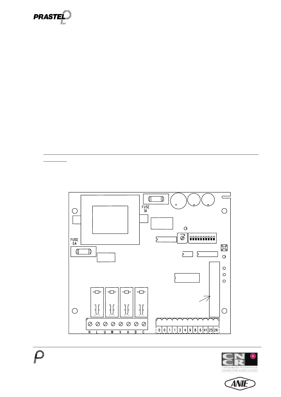
6.6 Programmazione del funzionamento della centrale tramite il trimmer T1 (Fig. 1)
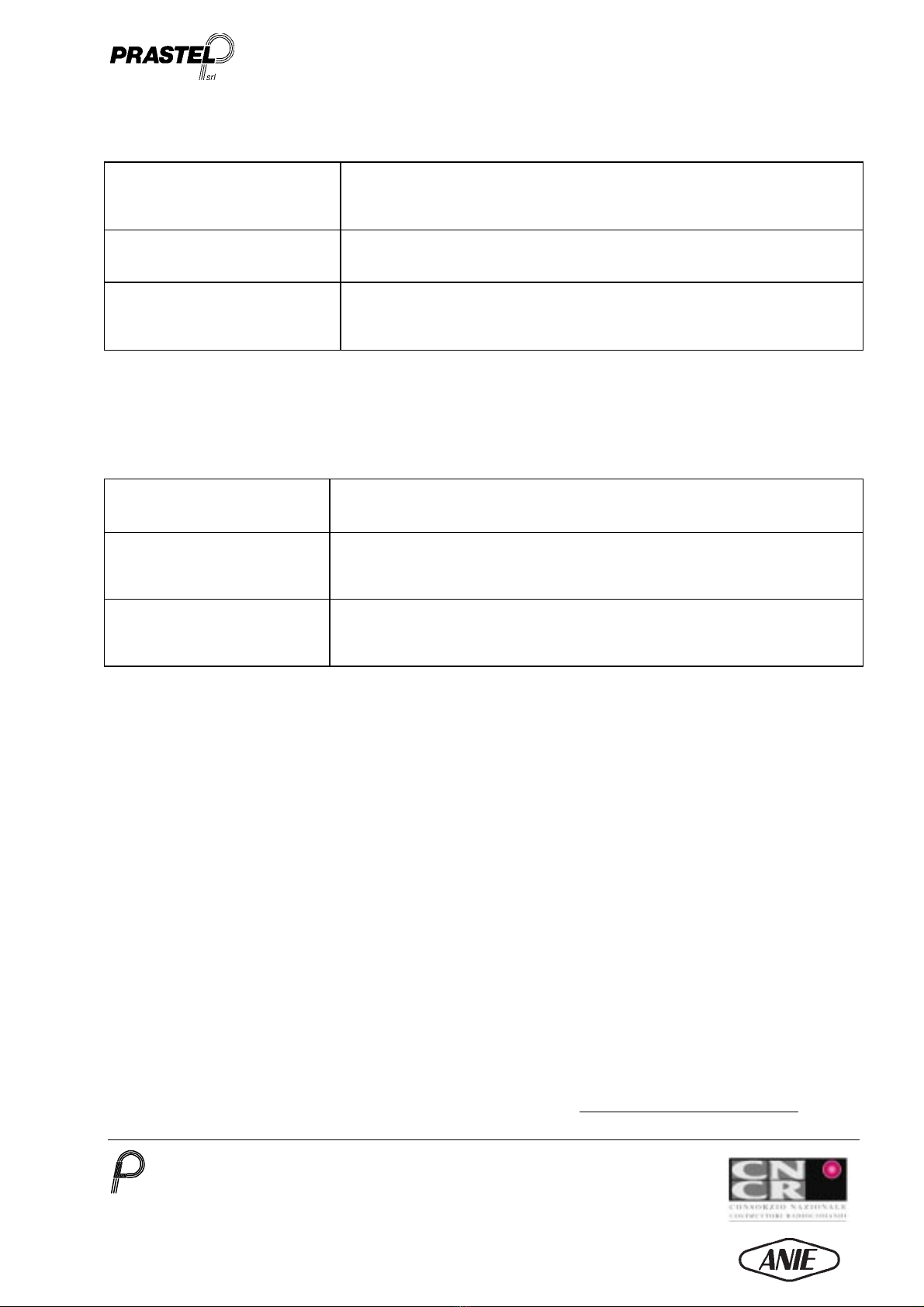
Impostazione del tempo di lavoro: 3 ÷ 45 sec
7. FUNZIONI FISSE DELLA CENTRALE
Lampeggiatore Frequenza di 2 Hz prefissata via software
Prelampeggio 2 sec in apertura e chiusura
Luce di Cortesia 3 min. rinnovabili ad ogni manovra
Ritardo d’inversione del senso di marcia del motore 1,5 sec
8. DESCRIZIONE DEL FUNZIONAMENTO DELLA CENTRALE
8.1 Generalità
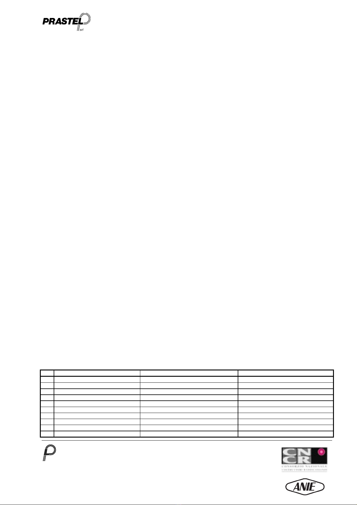
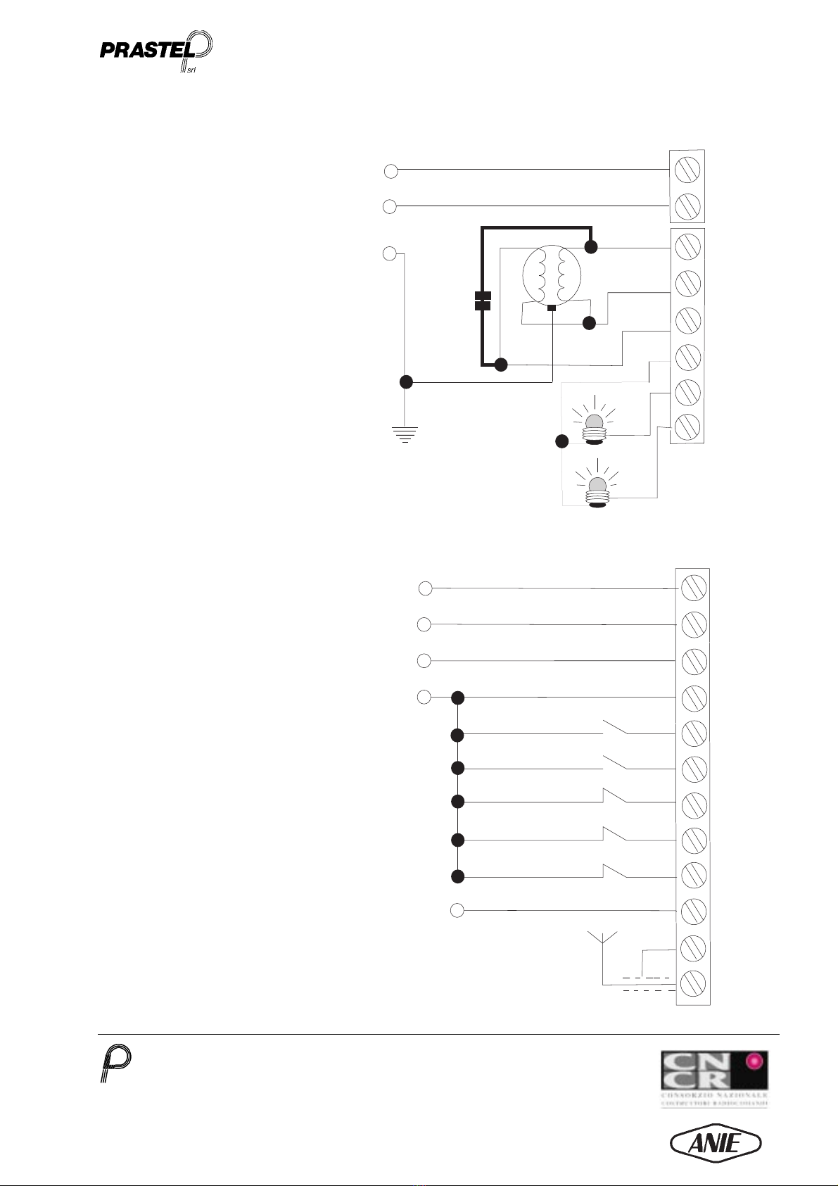
L’apparecchiatura è alimentata dalla tensione di rete (230 Vac evidenziata dall’accensione del LED 1 – fig.1), e fornisce sulla morsettiera di
potenza la tensione per l’alimentazione del motore dell’automazione. Sono disponibili, oltre al comune di alimentazione, due uscite per pilotare
separatamente i due versi di rotazione del motore.
N.B. Quando la centrale viene accesa, non viene eseguita alcuna manovra se non dopo il ricevimento di un comando volontario da parte
dell’utilizzatore
8.2 Comandi contrastanti
In presenza di comandi contrastanti contemporanei, la centrale non ne esegue nessuno.
8.3 Arresto motore
Può avvenire nei seguenti casi:
•Mancanza di alimentazione
•Intervento di una della sicurezza bassa (fotocellula), configurata per lo stop in entrambi i sensi di marcia (dip-switch 4 in
posizione ON)
•Fine del tempo massimo di lavoro impostato con il trimmer T1.
•Arresto prima di ogni manovra d’inversione per protezione motore (pre-impostato a 1.5 sec)
•Attivazione del pulsante di STOP (apertura del contatto N.C. di stop)
In questo caso per ripristinare il movimento, sbloccare il pulsante
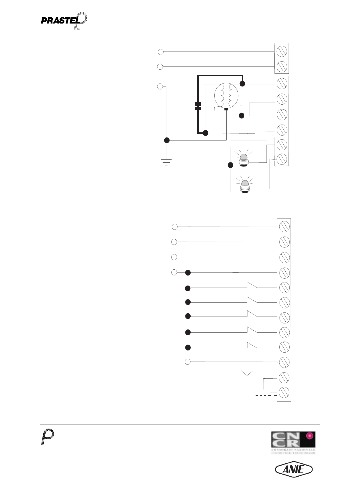
di Stop e dare un ulteriore comando via Radio o “APRE” o “CHIUDE” (morsetti 1-4 “CHIUDE” e 1-3 “APRE”).
•Comandi di STOP effettuati via Radio o tramite il comando “APRE” (morsetti 1 e 3) impostati con funzionamento passo-passo
(rispettivamente dip-switch 1 e 2 in posizione ON), o chiusura centralizzata tramite il 4° canale.
8.4 Manovra a uomo presente
•Premere il pulsante di STOP (apertura del contatto N.C. sui morsetti 1 e 9). A questo punto la centrale può eseguire la funzione ad
“Uomo presente” che prevede l’apertura e la chiusura dell’accesso automatizzato tramite due contatti esterni N.O. (morsetti 1-3,1-4 della
morsettiera di comando). Tali comandi (chiusura dei contatti N.O.) devono essere mantenuti volontariamente dall’operatore.
N.B. Durante la manovra a “Uomo presene” resta attiva solo la sicurezza “Bassa” (fotocellula).
N.B. E’ sempre necessario che il contatto di Stop sia chiuso per permettere il funzionamento automatico della centralina.
8.5 Manovra d’apertura
1. Fornire il comando, via radio o tramite comando APRE (morsetti 1 e 3)
2. Si attiva il prelampeggio, del segnalatore luminoso, della durata di 2 sec e l’eventuale luce di cortesia collegata alimentate direttamente
dalla centrale (max. 60 W per ognuna).
3. Se abilitato con il dip-switch 3 in posizione ON, viene effettuato automaticamente il test della sicurezza in apertura (sicurezza“Alta”)
4. Il motore resta in funzione per un tempo pari al tempo di lavoro configurato tramite il trimmer T1, mentre il lampeggiante continua a
lampeggiare alla frequenza di 2 Hz e l’eventuale luce di cortesia rimane accesa per un tempo fisso di 3 min.
8.6 Manovra di chiusura
1. Fornire il comando, via radio solo in modalità passo-passo o tramite comando CHIUDE (morsetti 1 e 4).
2. Si attiva il prelampeggio del segnalatore luminoso, della durata di 2 sec e l’eventuale luce di cortesia collegata alimentate direttamente
dalla centrale (max. 60 W per ognuna).
3. Se abilitato con il dip-switch 3 in posizione ON, viene effettuato automaticamente il test della sicurezza in chiusura (sicurezza”Bassa”)

EURO/SER
______________________________________________________________________________________________________________________________________________________________________________________________________________________________________________________________________________________________________________________________________________________________________________________________________________________________________________________________
PRASTEL S.r.l.
Via del Vetraio, 7 40138 Bologna Italy - Tel. +39-051-6023311 Fax +39-051-538460
E-mail: info@prastel.com - Web site: http://www.prastel.com
EURO/SER IT 03_1999 6
MEMBER OF
4. Il motore resta in funzione per un tempo pari al tempo di lavoro configurato tramite il trimmer T1, mentre il lampeggiante continua a
lampeggiare alla frequenza di 2 Hz e l’eventuale luce di cortesia rimane accesa per un tempo fisso di 3 min.

EURO/SER
______________________________________________________________________________________________________________________________________________________________________________________________________________________________________________________________________________________________________________________________________________________________________________________________________________________________________________________________
PRASTEL S.r.l.
Via del Vetraio, 7 40138 Bologna Italy - Tel. +39-051-6023311 Fax +39-051-538460
E-mail: info@prastel.com - Web site: http://www.prastel.com
EURO/SER IT 03_1999 7
MEMBER OF
LINEA 230 Vac (L)
LINEA 230 Vac (N)
TERRA (Verde/Giallo)
(0) COMUNE ALIMENTAZIONE
-
(1) USCITA ALIMENTAZIONE + 24 Vdc-350 mA
(3) PULSANTE APRE
(4) PULSANTE CHIUDE
(6) INGRESSO SICUREZZA IN APERTURA
(8) INGRESSO FOTOCELLULA
(9) PULSANTE STOP DI EMERGENZA
(25) MASSA ANTENNA RADIO
(26) CENTRALE ANTENNA RADIO
(41) USCITA COMANDO FOTOTEST +24Vdc
(0) COMUNE ALIMENTAZIONE
-
(1) USCITA ALIMENTAZIONE + 24 Vdc-350 mA
A
0
L
N
U
W
V
A
0
1
3
4
9
8
6
41
25
26
APRE
COMUNE
CHIUDE
LAMPADINA per
lampeggiatore
230 Vac (max 60 W)
B
C
LUCE DI CORTESIA
230 Vac (max 60 W)
0
1

EURO/SER
______________________________________________________________________________________________________________________________________________________________________________________________________________________________________________________________________________________________________________________________________________________________________________________________________________________________________________________________
PRASTEL S.r.l.
Via del Vetraio, 7 40138 Bologna Italy - Tel. +39-051-6023311 Fax +39-051-538460
E-mail: info@prastel.com - Web site: http://www.prastel.com
EURO/SER IT 03_1999 8
MEMBER OF
MACHINE DIRECTIVE 98/37/CE, LOW VOLTAGE 73/23/CEE, EMC 89/336/CEE
ENGLISH
1. GENERAL INFORMATION
The EURO/SER control unit was conceived, designed and constructed for automated access control with the maximum
possible safety; the particular use for which this control unit was designed concerns the command and control of an
automatic shutter.
Compliance with the strict European reference standards (CE) is also a guarantee of the product's quality and
reliability.
2. MAIN CHARACTERISTICS
• Command and control of automated access points such as shutters with 1 motor (single-phase 1 HP)
• Easy programming of the functions by means of a 10-way binary dip-switch, a trimmer and a pushbutton.
• 433 MHz single-channel Rolling code receiver with 200 code memory
Complies with the following European technical standards
- Recommendation CEPT T/R 01-04
- I-ETS 300-220
• Complies with the European reference Directives:
Machine Directive 98/37/CE
Low Voltage 73/23/CEE
Electromagnetic Compatibility (EMC) 89/336/CEE
•Complies with the standard UNI 8612
3. TECHNICAL CHARACTERISTICS
Power supply: 230 Vac ± 10%
Motor output: Single-phase 1 HP
Motor current: Max 5 Amperes with fuse protection
Motor ignition TRIAC in series at the motor common power supply with double exchange relay
Terminal board pitch 7.62 mm for the power part (fixed); 5.08 mm for the command part (extractable)
Radio receiver Integrated with recognition of the univocal Rolling code or Multipass codes
Reception frequency : 433 MHz
Frequency stability: ± 100 KHz
Sensitivity: 1.4 µV
Passband: > 25 KHz
No. of codes that can be memorised: 200
Storage temperature: - 40 °C / + 55°C
No. of channels that can be selected: 3. The 4th channel commands the centralised
closing
Accessory power supply: 24 Vdc - 350 mA with fuse protection
Working temperature: -15°C / + 55 °C
Reference parameters: memorised in EE-PROM

EURO/SER
______________________________________________________________________________________________________________________________________________________________________________________________________________________________________________________________________________________________________________________________________________________________________________________________________________________________________________________________
PRASTEL S.r.l.
Via del Vetraio, 7 40138 Bologna Italy - Tel. +39-051-6023311 Fax +39-051-538460
E-mail: info@prastel.com - Web site: http://www.prastel.com
EURO/SER IT 03_1999 9
MEMBER OF
Function handler: microprocessor equipped with watch-dog
Dimensions: 255 x 177 x 95 mm
Weight 1100 gr

EURO/SER
______________________________________________________________________________________________________________________________________________________________________________________________________________________________________________________________________________________________________________________________________________________________________________________________________________________________________________________________
PRASTEL S.r.l.
Via del Vetraio, 7 40138 Bologna Italy - Tel. +39-051-6023311 Fax +39-051-538460
E-mail: info@prastel.com - Web site: http://www.prastel.com
EURO/SER IT 03_1999 10
MEMBER OF
4. CONNECTION AND START-UP OF THE CONTROL UNIT
•Before installing the EURO/SER control unit read the
“General safety warnings”
.
•Fix the box by means of the relative fixing holes.
•Provide a switch / disconnector on the mains power supply as foreseen by the current reference standards.
•Disconnect the power supply before connecting the power cables.
•Fix the cable glands provided (PG 7) and insert the cables, keeping the 230 Vac power cables separate from the 24 Vdc command
cables (diagram on page 6).
•Connect the power and command cables as shown in the diagram on page 6, bearing the following points in mind:
•Connect the devices provided for the best possible safety on the automated access point on which the control unit is installed.
The connection to terminal 41 is only necessary if devices with built-in autotest function are installed (Prastel devices FOTO/30SDE,
FOTOTEST/2, FOTO/35SDE, etc.).
•The STOP pushbutton must be the manual release type.
•Before switching on block the STOP pushbutton; it is now possible to carry out the maneuvers, known as "OPERATOR PRESENT", by
means of the OPEN and CLOSE contacts (N.O. contacts to be connected to the terminals 1 and 4 (close) and 1 and 3 (open) on the
command terminal board; see diagram on page 6). Opening and closing take place when the aforesaid contacts are closed..
N.B. during the operator present maneuvers only the photocell security device is activated (connection on terminals 1-8)
•Release the STOP pushbutton
•Select the required functioning options by means of the relative dip-switches
•Programme one or more transmitters, according to the procedures indicated in paragraph 6.1 "Code programming and cancelling", and
carry out all the command maneuvers possible by radio or manually (terminals 1-4, 1-3).
Fixed power terminal board Extractable command
terminal board
Dip-switch ON
OFF
1 2 3 4 5 6 7 8 9 10
T1 P1
RADIO
LD1
LD2
Fig. 1

EURO/SER
______________________________________________________________________________________________________________________________________________________________________________________________________________________________________________________________________________________________________________________________________________________________________________________________________________________________________________________________
PRASTEL S.r.l.
Via del Vetraio, 7 40138 Bologna Italy - Tel. +39-051-6023311 Fax +39-051-538460
E-mail: info@prastel.com - Web site: http://www.prastel.com
EURO/SER IT 03_1999 11
MEMBER OF
5. SAFETY DEVICES
5.1 PHOTOCELLS
“Low” safety (photocell)
Intervention mode selectable bydip-switch between:
•direction reversal during closing
•stop in both directions
“High” safety (barrier for
opening safety)
Intervention mode:
•direction reversal during opening
Autotest
Selected by dip-switch between:
•autotest on all the safety devices enabled
•autotest on all the safety devices disabled
The autotest function consists of sending a positive impulse (24 Vdc- on terminal 41) to the test input of the safety devices installed and
detecting the response on the output contact. Therefore, if autotest on all the safety devices is selected, these must all be present and have
built-in autotest function (e.g. Prastel photocells model FOTO/30 SDE, FOTOTEST/2, FOTO/35SDE, etc…).
5.2 CONTROL UNIT PROTECTION
Motor protection
The motor and the power circuits are protected by a 5A rapid fuse (format 5x20).
Protection of the Triac against overvoltage by means of MOV
Transformer protection
The secondary winding of the transformer is protected by a 1A rapid fuse, (format 5x20).
Protection against overvoltage by means of MOV on the primary and secondary windings of the
transformer.
Automatic reset
In the event of irregular microprocessor functioning, an independent automatic reset circuit (watch-
dog) resets unit control, restoring it to the initial conditions at switching on.
6. CONTROL UNIT PROGRAMMING
Control unit programming is divided into two parts:
•Programming and cancelling by means of the pushbutton P1, of the radio-transmitted codes (Fig. 1)
•Functioning programming by means of the trimmer T1 and the 10-way binary dip-switch (Fig. 1)
6.1 Programming and cancelling of the codes via radio
By means of the built-in receiver it is possible to memorise the Multipass codes (fixed codes) or the Rolling codes (variable codes) using the
single pushbutton P1 (Fig. 1)
Rolling Code
The purpose of this code is to prevent the possibility of code violation by capture and retransmission. The rolling code involves the
transmission of a frame of bits, different for each transmitter, consisting of a part that varies in a pseudo-random way (rolling code) with each
transmission according to a proprietary algorithm, i.e. the configuration of these bits varies in an unpredictable way from one transmission to
the next. The receiver memorises the code of each transmitter by self-learning, up-dating it at each transmission. The transmitter is
recognised only if it sends a rolling code corresponding to the 255 configurations subsequent, but not consecutive, to the last transmission
recognised. It does, however, allow re-alignment and recognition of a previously memorised transmitter that has gone outside the allowed
range (for example, due to an excess of transmissions made a long way from the automated access or on replacement of the batteries only on
certain models), by pressing and releasing the transmitter learning pushbutton: the correctness of the code is analysed, maintaining the
advantages of the variable code.
Management by means of the GT/BASER portable terminal
All the programming can be carried out with the GT/BASER portable terminal except for insertion of the password

EURO/SER
______________________________________________________________________________________________________________________________________________________________________________________________________________________________________________________________________________________________________________________________________________________________________________________________________________________________________________________________
PRASTEL S.r.l.
Via del Vetraio, 7 40138 Bologna Italy - Tel. +39-051-6023311 Fax +39-051-538460
E-mail: info@prastel.com - Web site: http://www.prastel.com
EURO/SER IT 03_1999 12
MEMBER OF
6.1.1 Programming
•Power up the receiver
•Press the pushbutton P1: the red LED lights up indicating that programming is in progress
•Carry out a transmission by pressing any of the transmitter buttons
•The code is inserted in the memory. During insertion the LED flashes. On completion, the LED returns to steadystate, indicating that a
new code can be inserted.
•Memorise all the transmitters, carrying out a transmission with each of them with a maximum interval of 10 sec.
•On completion of the operation, press the pushbutton P1 again to exit from the procedure. The LED goes out. Exit from the procedure
takes place in any case automatically after 10 sec. of non-activity.
•Even if the receiver is disconnected from the power supply, the codes remain in the memory
6.2 Total cancelling of the codes
•Press and hold down the pushbutton P1 until the red LED starts to flash (approx. 3 sec)
•Press the pushbutton P1 again within 6 sec. to confirm cancelling. Confirmation is indicated bythe LED flashing at the highest
frequency.
6.3 Remote enabling of new “Rolling Code” transmitters
To enable a new transmitter without intervening on the receiver, it is necessary to use an already enabled transmitter.
1. Press and release the learning pushbutton, accessible through the small hole on the rear of the transmitter. Carry out this operation within
the maximum reception range.
2. Carry out a transmission by pressing one of the channel pushbuttons on the transmitter to be enabled.
3. Enable all the new transmitters by pressing a channel pushbutton on each of them.
4. Exit from the enabling phase by pressing a channel pushbutton on the transmitter used to enter the procedure. The procedure will in any
case be exited 10 sec. after the last transmission.
5. Check that the transmitters have been programmed by carrying out opening of the access point with each of them.
6.4 Functioning irregularities of the transmitters
A) In the event of non-functioning, check whether the indicator LED lights up. Non-functioning of the LED could indicate that the battery is
flat. Change the battery and check the functioning of the transmitter.
B) The transmitters with Rolling codes could lose alignment with the control unit receiver in the following cases:
- Enabling of the transmitter outside the maximum range of the receiver more than 256 times .
- Battery change.
To re-align the transmitters, proceed as follows:
1. Press and release the learning pushbutton, accessible through the small hole on the rear of the transmitter, activating the remote
enabling phase.
2. To exit from the programming mode, press one of the channel pushbuttons or wait 10 sec. to exit automatically.
C) If the transmitter still does not function, check that other enabled transmitters are functioning correctly since the problem could be in the
control unit.
6.5 Functioning programming by means of the 10-way binary dip-switch (Fig. 1)
N° FUNCTIONING OFF ON
1 OPEN pushbutton opening sequence Open Open-Stop-Close-Stop
2 Opening sequence via radio Open-Close Open-Stop-Close-Stop
3 Autotest Disabled Enabled for all safety devices
4 Closing safety mode Stop in both directions Inversion of direction in closing
5 Channel 1 (*) Disabled Enabled
6 Channel 2 (*) Disabled Enabled
7 Channel 3 (*) Disabled Enabled
8 Not connected
9 Not connected
10 Not connected

EURO/SER
______________________________________________________________________________________________________________________________________________________________________________________________________________________________________________________________________________________________________________________________________________________________________________________________________________________________________________________________
PRASTEL S.r.l.
Via del Vetraio, 7 40138 Bologna Italy - Tel. +39-051-6023311 Fax +39-051-538460
E-mail: info@prastel.com - Web site: http://www.prastel.com
EURO/SER IT 03_1999 13
MEMBER OF
(*) Channel 4 is always "Enabled". It is, for example, possible, with a single command, to carry out centralised and simultaneous closing
of several automatic shutters installed within the maximum permitted range of the transmitter.

EURO/SER
______________________________________________________________________________________________________________________________________________________________________________________________________________________________________________________________________________________________________________________________________________________________________________________________________________________________________________________________
PRASTEL S.r.l.
Via del Vetraio, 7 40138 Bologna Italy - Tel. +39-051-6023311 Fax +39-051-538460
E-mail: info@prastel.com - Web site: http://www.prastel.com
EURO/SER IT 03_1999 14
MEMBER OF
6.6 Programming of the control unit functioning by means of the trimmer T1 (Fig. 1)
Setting of the working time: 3 - 45 sec
7. FIXED FUNCTIONS OF THE CONTROL UNIT
Flashing light Frequency of 2 Hz preset via software
Pre-flashing 2 sec in opening and closing
Courtesy light 3 min. renewable at each maneuver
Inversion delay in the motor running direction 1.5 sec
8. FUNCTIONING DESCRIPTION OF THE CONTROL UNIT
8.1 General
The device is powered by the mains power supply (230 Vac indicated by lighting up of the LED 1 – fig. 1), and provides power to the
automated access point motor through the power terminal board. In addition to the common power supply, two outputs are available for
separate control of the two rotation directions of the motor
N.B. When the control unit is switched on, no maneuver is carried out until a voluntary command is received from the user.
8.2 Conflicting commands
In the event of simultaneous conflicting commands, the control unit does not carry out anycommand
8.3 Motor stop
This may occur in the following cases:
•Power supply failure
•Intervention of one of the low safetydevices (photocell) configured for the stop in both directions (dip-switch 4 in position ON)
•End of the maximum working time set with the trimmer T1.
•Stop before every inversion maneuver for motor protection (pre-set at 1.5 sec)
•Activation of the STOP pushbutton (opening of theN.C. stop contact).
In this case to reset the movement, release the Stop pushbutton
and activate another "OPEN" or "CLOSE" command via Radio (terminals 1-4 “CLOSE” e 1-3 “OPEN”).
•STOP command given via Radio or by means of the “OPEN” command (terminals 1 and 3) set with step functioning (respectively dip-
switches 1 and 2 in position ON), or centralised closing by means of channel 4.
8.4 Maneuver with operator present
•Press the STOP pushbutton (opening of the N.C. contact on the terminals 1 and 9). At this point the control unit can carry out the
"Operator present" function which allows opening and closing of the automated access point by means of two external N.O. contacts
(terminals 1-3,1-4 of the control terminal board). These commands (closing of the N.O. contacts) must be maintained voluntarily by the
operator.
N.B. During the "Operator present" maneuver, only the "Low" safety device (photocell) remains activated.
N.B. It is always necessary for the Stop contact to be closed to allow automatic functioning of the control unit.
8.5 Opening maneuver
1. Give the command via radio or by means of the OPEN command (terminals 1 and 3)
2. Pre-flashing of the luminous indicator, lasting for 2 sec., is activated and the courtesy light if fitted powered directly by the control unit
(max. 60 W for each one).
3. If enabled with thedip-switch 3 in position ON, the test of the opening safetydevices is carried out automatically (“High” safety).
4. The motor remains in operation for a time equal to the working time set by means of the trimmer T1, while the indicator continues to flash
at a frequency of 2 Hz and the courtesy light remains on for a fixed time of 3 min.
8.6 Closing maneuver
1. Give the command via radio only in step mode or by means of the CLOSE command (terminals 1 and 4).
2. Pre-flashing of the luminous indicator, lasting for 2 sec., is activated and the courtesy light if fitted powered directly by the control unit
(max. 60 W for each one).
3. If enabled with thedip-switch 3 in position ON, the test of the closing safetydevices is carried out automatically (“Low” safety”)
4. The motor remains in operation for a time equal to the working time set by means of the trimmer T1, while the indicator continues to flash
at a frequency of 2 Hz and the courtesy light remains on for a fixed time of 3 min.

EURO/SER
______________________________________________________________________________________________________________________________________________________________________________________________________________________________________________________________________________________________________________________________________________________________________________________________________________________________________________________________
PRASTEL S.r.l.
Via del Vetraio, 7 40138 Bologna Italy - Tel. +39-051-6023311 Fax +39-051-538460
E-mail: info@prastel.com - Web site: http://www.prastel.com
EURO/SER IT 03_1999 15
MEMBER OF
LINE 230 Vac (L)
LINE 230 Vac (N)
GROUND (Green/Yellow )
(0) COMMON POWER SUPPLY
-
(1) POWER SUPPLY OUTPUT + 24 Vdc-350 mA
(3) OPEN PUSH BUTTON
(4) CLOSE PUSH BUTTON
(6) OPENING SAFETY DEVICE INPUT
(8) PHOTOCELL INPUT
(9) EMERGENCY STOP PUSH BUTTON
(25) RADIO ANTENNA EARTH
(26) RADIO ANTENNA POWER UNIT
(41) FOTOTEST COMMAND OUTPUT +24Vdc
(0) COMMON POWER SUPPLY
-
(1) POWER SUPPLY OUTPUT + 24 Vdc-350 mA
A
0
L
N
U
W
V
A
0
1
3
4
9
8
6
41
25
26
OPEN
COMMON
CLOSE
FLASHING LIGHT
230 Vac (max 60 W)
B
C
COURTESY LAMP
230 Vac (max 60 W)
0
1

EURO/SER
______________________________________________________________________________________________________________________________________________________________________________________________________________________________________________________________________________________________________________________________________________________________________________________________________________________________________________________________
PRASTEL S.r.l.
Via del Vetraio, 7 40138 Bologna Italy - Tel. +39-051-6023311 Fax +39-051-538460
E-mail: info@prastel.com - Web site: http://www.prastel.com
EURO/SER IT 03_1999 16
MEMBER OF
DIRECTIVE MACHINES 98/37/CE, BASSE TENSION 73/23/CEE, EMC 89/336/CEE
FRANÇAIS
1. INFORMATIONS GENERALES
La centrale EURO/SER a été conçue, projetée et réalisée pour gérer de la manière la plus sûre possible un accès
automatisé ; cette centrale a été étudiée pour la commande et le contrôle d'un volet automatique.
La conformité aux sévères standards européens de référence (CE) est en outre la garantie de la qualité et de la fiabilité
du produit.
2. CARACTERISTIQUES PRINCIPALES
• Commande et contrôle d'accès automatisés tels que les volets à un moteur (monophasé 1 HP)
• Programmation facile des fonctions à l'aide d'un commutateur binaire à 10 voies, d'un trimmer et d'un bouton.
• Récepteur 433 MHz monocanal Rolling code avec une mémoire de 200 codes
Conforme aux normes techniques européennes suivantes :
- Recommandation CEPT T/R 01-04
- I-ETS 300-220
• Conforme aux directives européennes de référence :
Directive Machines 98/37/CE
Basse Tension 73/23/CEE
Compatibilité électromagnétique (EMC) 89/336/CEE
•Conforme à la norme UNI 8612
3. CARACTERISTIQUES TECHNIQUES
Alimentation : 230 Vac ± 10%
Sortie moteur : Monophasé 1 HP
Courant moteur : Max. 5 Ampères protégé par un fusible
Allumage moteur : A TRIAC en série au neutre d'alimentation moteur avec relais à double échange
Pas boîte à bornes : 7,62 mm pour la partie puissance (fixe) ; 5,08 mm pour la partie commande (amovible)
Récepteur radio : Intégré avec reconnaissance des codes univoques Multipass ou Rolling code
Fréquence de réception : 433 MHz
Stabilité fréquence : ± 100 KHz
Sensibilité : 1,4 µV
Bande passante : > 25 KHz
N.bre de codes mémorisables : 200
Température de stockage : - 40 °C / + 55°C
N.bre de canaux sélectionnés : 3. Le 4ème commande la fermeture centralisée.
Alim. accessoires : 24 Vdc - 350 mA protégée par un fusible
Temp. fonctionnement : -15°C / + 55 °C
Paramètres de référence : mémorisables en EE-PROM
Gestionnaire fonctions : microprocesseur muni de chien de garde
Dimensions : 255 x 177 x 95 mm

EURO/SER
______________________________________________________________________________________________________________________________________________________________________________________________________________________________________________________________________________________________________________________________________________________________________________________________________________________________________________________________
PRASTEL S.r.l.
Via del Vetraio, 7 40138 Bologna Italy - Tel. +39-051-6023311 Fax +39-051-538460
E-mail: info@prastel.com - Web site: http://www.prastel.com
EURO/SER IT 03_1999 17
MEMBER OF
Poids : 1100 g

EURO/SER
______________________________________________________________________________________________________________________________________________________________________________________________________________________________________________________________________________________________________________________________________________________________________________________________________________________________________________________________
PRASTEL S.r.l.
Via del Vetraio, 7 40138 Bologna Italy - Tel. +39-051-6023311 Fax +39-051-538460
E-mail: info@prastel.com - Web site: http://www.prastel.com
EURO/SER IT 03_1999 18
MEMBER OF
4. RACCORDEMENT ET MISE EN FONCTION DE LA CENTRALE
•Avant d'installer la centrale EURO/SER, lire les "
Mises en garde générales concernant la sécurité
"-
•Fixer le boîtier à l'aide des orifices de fixage prévus à cet effet.
•Installer un interrupteur / disjoncteur sur le réseau d'alimentation, conformément aux normes de référence en vigueur.
•Couper l'alimentation avant de raccorder les câbles de puissance.
•Fixer les serre-câbles fournis (PG 7) et faire passer les câbles en séparant les câbles de puissance à 230 Vac de ceux de commande à
24 Vdc (schéma page 6).
•Raccorder les câbles de puissance et de commande conformément aux indications du schéma de la page 6 en respectant les points
suivants :
•Raccorder les dispositifs prévus pour une sécurité maximale sur l'automation où sera installée la centrale. La borne 41 ne doit être
raccordée qu'en cas d'installation de dispositifs avec fonction d'autotest incorporée (dispositifs Prastel FOTO/30SDE, FOTOTEST/2,
FOTO/35SDE, etc.).
•Le bouton de STOP relié doit être à déblocage manuel.
•Avant de mettre l'installation sous tension, bloquer le bouton de STOP ; vous pouvez maintenant effectuer les manœuvres, dites de
l'"HOMME PRESENT", à l'aide des contacts OUVRE et FERME (contacts N.O. à relier aux bornes 1 et 4 (ferme) et 1 et 3 (ouvre) de la
boîte à bornes de commande (voir schéma page 6). L'ouverture et la fermeture se font en maintenant la fermeture des contacts
susmentionnés.
N.B.
Pendant les manœuvres d'homme présent, seul le dispositif de sécurité de la cellule photoélectrique (raccordement aux bornes 1
à 8) est activé.
•Débloquer le bouton de STOP.
•Sélectionner les options de fonctionnement souhaitées à l'aide des commutateurs prévus à cet effet.
•Programmer un ou plusieurs émetteurs selon les modalités figurant au paragraphe 6.1 "Programmation et effaçage des codes" et
effectuer toutes les manœuvres de commande possible par radio ou manuellement (bornes 1-4, 1-3).
Bornier fixe de puissance Bornier amovible de
commande
CommutateurON
OFF
1 2 3 4 5 6 7 8 9 10
T1 P1
RADIO
LD1
LD2
Fig. 1

EURO/SER
______________________________________________________________________________________________________________________________________________________________________________________________________________________________________________________________________________________________________________________________________________________________________________________________________________________________________________________________
PRASTEL S.r.l.
Via del Vetraio, 7 40138 Bologna Italy - Tel. +39-051-6023311 Fax +39-051-538460
E-mail: info@prastel.com - Web site: http://www.prastel.com
EURO/SER IT 03_1999 19
MEMBER OF

EURO/SER
______________________________________________________________________________________________________________________________________________________________________________________________________________________________________________________________________________________________________________________________________________________________________________________________________________________________________________________________
PRASTEL S.r.l.
Via del Vetraio, 7 40138 Bologna Italy - Tel. +39-051-6023311 Fax +39-051-538460
E-mail: info@prastel.com - Web site: http://www.prastel.com
EURO/SER IT 03_1999 20
MEMBER OF
5. DISPOSITIFS DE SECURITE
5.1 CELLULES PHOTOELECTRIQUES
Sécurité “basse ” (cellule photo.) Modalité d'intervention sélectionnable à l'aide du commutateur entre :
•inversion du sens de la marche en fermeture
•stop dans les deux sens
Sécurité “élevée” (barrière de
sécurité en ouverture)
Modalité d'intervention :
•inversion du sens de la marche en ouverture
Autotest Sélectionnable à l'aide du commutateur entre :
•habilite l'autotest de toutes les sécurités
•déshabilite l'autotest de toutes les sécurités
La fonction d'autotest consiste à envoyer une impulsion positive (24 Vdc- à la borne 41) à l'entrée de test des dispositifs de sécurité qui en
sont munis et à détecter la réponse sur le contact de sortie correspondant. Par conséquent, si l'on choisit d'effectuer l'autotest sur toutes les
sécurités, celles-ci devront toutes être présentes et avec fonction d'autotest incorporée (ex. cellule photoélectrique Prastel modèle FOTO/30
SDE, FOTOTEST/2, FOTO/35SDE, etc.).
5.2 PROTECTION DE LA CENTRALE
Protection du moteur Le moteur et les circuits de puissance sont protégés par un fusible de 5A rapide (format 5x20).
Protection du Triac contre les surtensions à l'aide du MOV.
Protection du transformateur Le secondaire du transformateur est protégé par un fusible de 1 A rapide, (format 5x20).
Protection contre les surtensions à l'aide du MOV sur le primaire et le secondaire du
transformateur.
Réarmement automatique En cas de fonctionnement anormal du microprocesseur, un circuit indépendant de réarmement
automatique (chien de garde) rétablit le contrôle de la centrale en la ramenant aux conditions
initiales d'allumage.
6. PROGRAMMATION DE LA CENTRALE
La programmation de la centrale est divisée en deux parties :
•Programmation et effaçage, à l'aide du bouton P1, des codes transmis par radio (Fig. 1)
•Programmation du fonctionnement à l'aide du trimmer T1 et du commutateur binaire à 10 voies (Fig. 1)
6.1 Programmation et effaçage des codes par radio
Lerécepteur intégréà lacentrale permet de mémoriser des codes Multipass (codes fixes) ou des codes Rolling (codes variables) à l'aide du
seul bouton P1 (Fig. 1)
Codification Rolling
Cette codification a pour but d'empêcher toute violation du code pour capture et retransmission. La codification rolling comporte la
transmission d'une trame de bit, différente pour chaque émetteur, composée d'une partie qui varie à chaque transmission en mode pseudo-
random (code rolling) en fonction d'un algorithme propriétaire, c'est-à-dire que la configuration de ces bits change d'une transmission à l'autre
de manière imprévisible. Le récepteur mémorise le code de chaque émetteur par auto-apprentissage en le mettant à jour à chaque
transmission. L'émetteur est reconnu uniquement s'il envoie un code rolling correspondant aux 255 configurations successives, mais non
consécutives, à la dernière transmission reconnue. Cela permet toutefois le réalignement et la reconnaissance d'un émetteur mémorisé
précédemment hors de l'intervalle autorisé (en raison, par exemple, d'un excès de transmissions effectuées loin de l'automatisation ou du
remplacement des piles d'alimentation, uniquement sur certains modèles), en enfonçant puis en relâchant le bouton d'auto-apprentissage de
l'émetteur : la justesse du code est ainsi analysée tout en maintenant les avantages de la codification variable.
Gestion à l'aide d'un terminal portable GT/BASER
Le terminal portable GT/BASER permet de réaliser toutes les programmations possibles à l'exception de la saisie du mot de passe.
Table of contents
Languages:
Other PRASTEL Control Unit manuals

PRASTEL
PRASTEL EASY-PAD User manual

PRASTEL
PRASTEL MT15000/EXT-IO Owner's manual

PRASTEL
PRASTEL M2000PE User manual

PRASTEL
PRASTEL M1000 User manual

PRASTEL
PRASTEL FSTYLE25A User manual

PRASTEL
PRASTEL UNIK3I-V4 Safety guide

PRASTEL
PRASTEL M1000E User manual

PRASTEL
PRASTEL GT+ User manual

PRASTEL
PRASTEL UNIK1E User manual

PRASTEL
PRASTEL MT15000/2 Owner's manual
Popular Control Unit manuals by other brands

Cavli Wireless
Cavli Wireless C16QS Hardware manual

ITW Gema
ITW Gema EasyTronic Operating instructions and spare parts list

wtw
wtw IQ SENSOR NET MIQ/A operating manual

Biamp
Biamp IMPERA ECHO installation manual

Panasonic
Panasonic HIT VBHN340SA17E General installation manual

Pentair
Pentair FLECK 5812 XTR2 Service manual