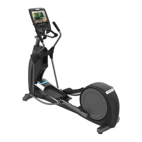
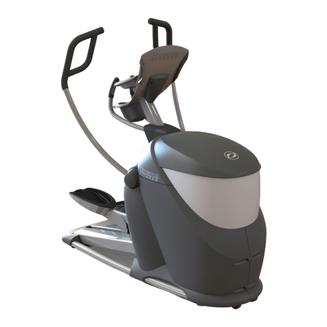
Precor Discovery Series User manual
Other Precor Elliptical Trainer manuals
Precor
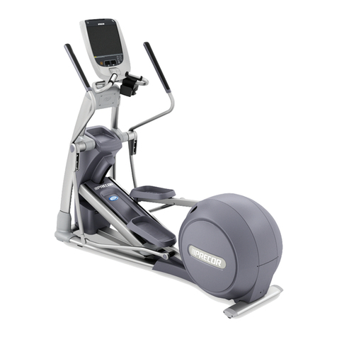
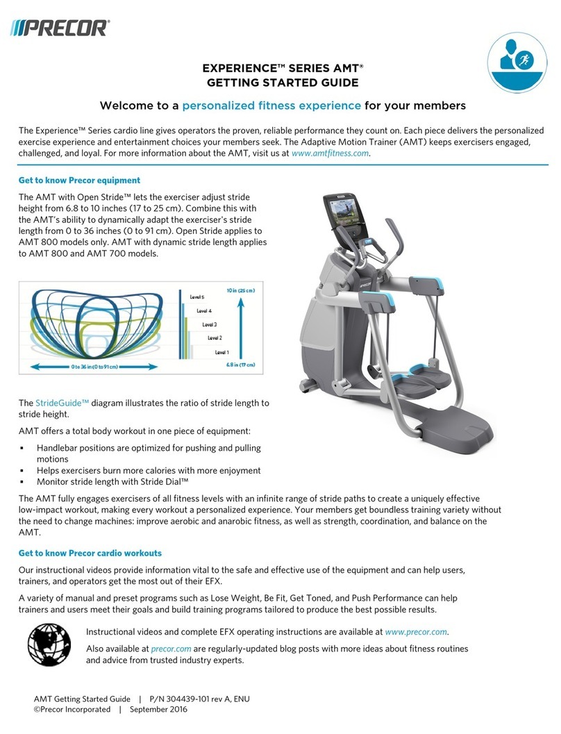
Precor Experience 700 line Series User manual
Precor
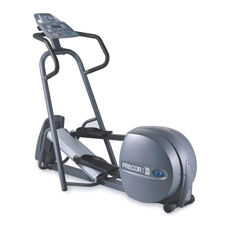
Precor EFX 5.17i User manual
Precor
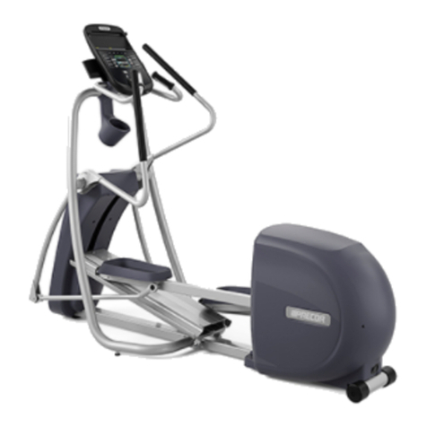
Precor Precision 400 Series User manual
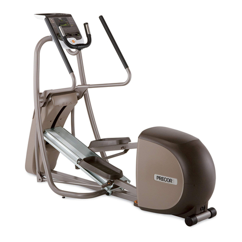
Precor
Precor EFX5.31 User manual
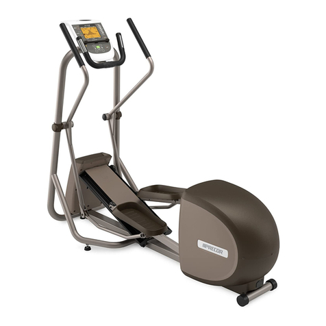
Precor
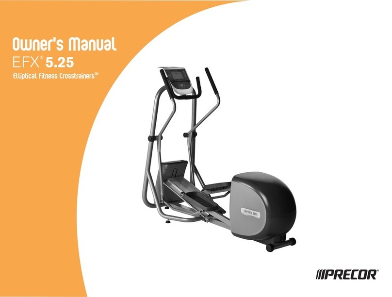
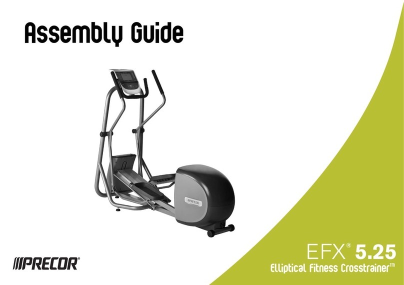
Precor Elliptical Fitness Crosstrainer EFX 5.25 User manual
Precor
Precor C532i User manual
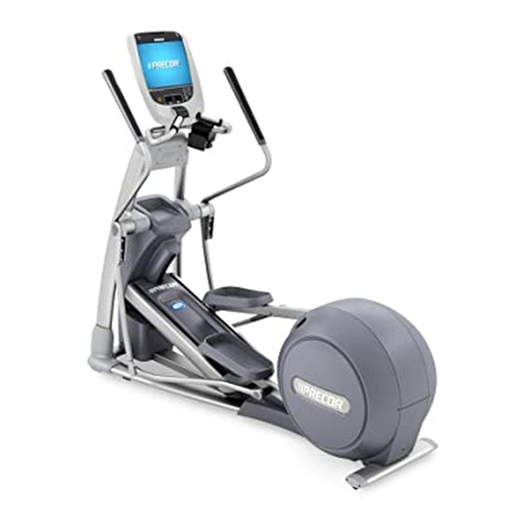
Precor
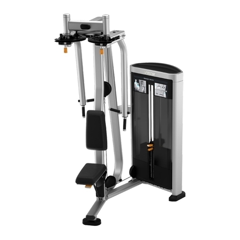
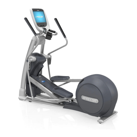
Precor EFX 885 Assembly Instructions
Precor
Precor Resolute RSL 505 User manual
Precor
Precor Elliptical Fitness Crosstrainer EFX 5.25 User manual

Precor
Precor C546i User manual
Precor
Precor EFX 883 Assembly Instructions
Precor
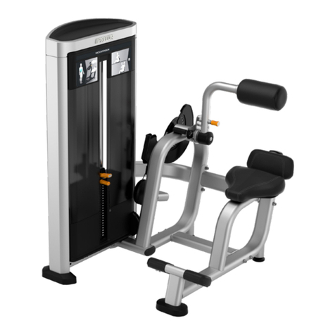
Precor Experience Sereis User manual
Precor
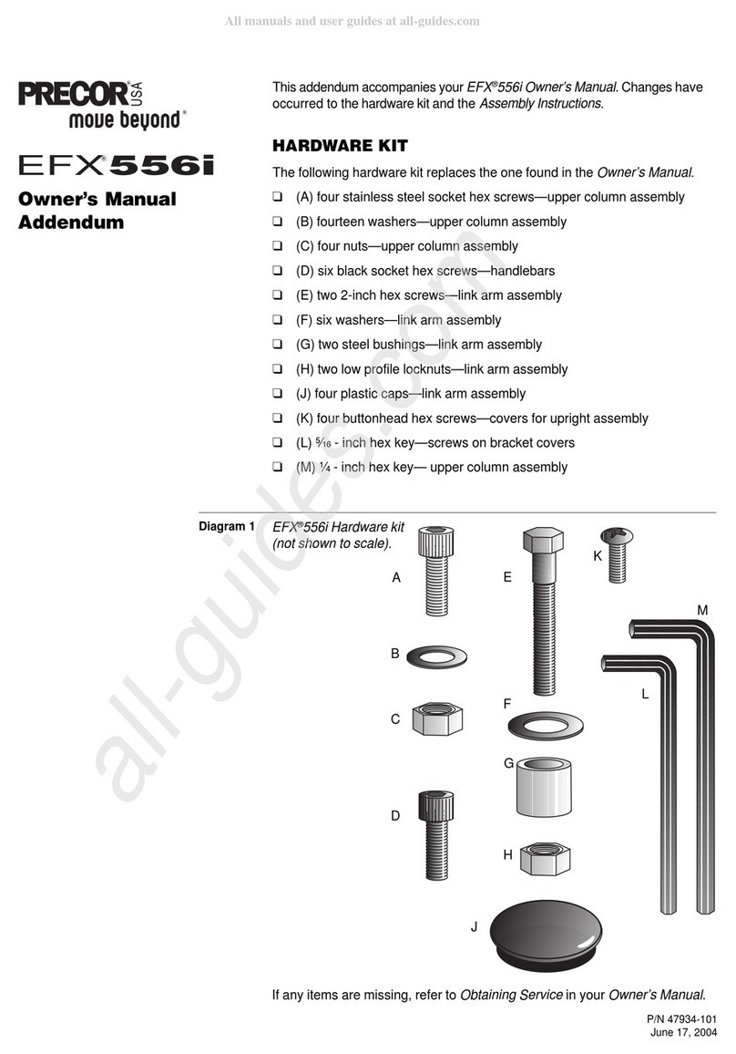
Precor Resolute RSL 313 User manual
Precor
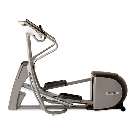
Precor EFX 556i Installation and operating instructions
Precor
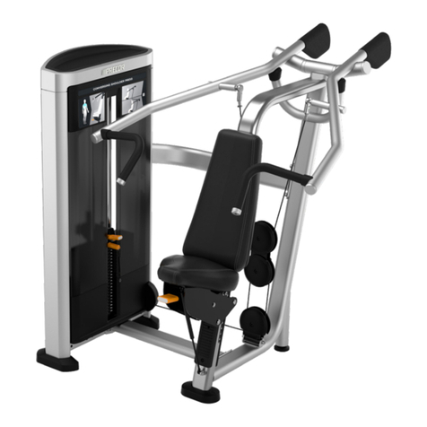
Precor 5.37 User manual
Precor
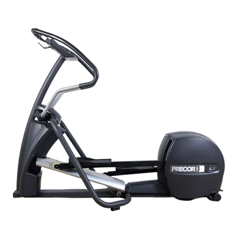
Precor Resolute RSL 515 User manual
Precor
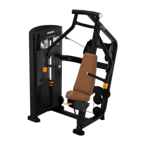
Precor EFX 5.21i User manual
Precor
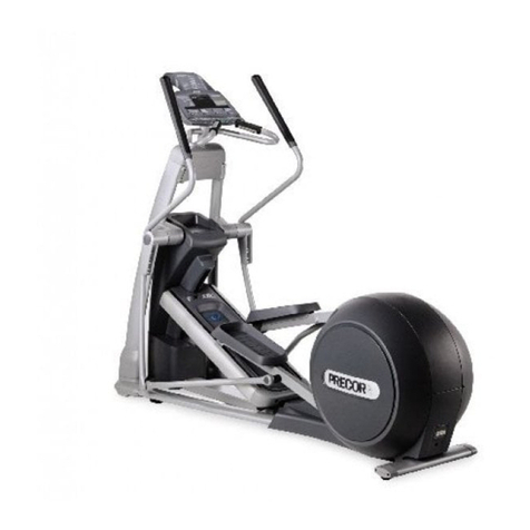
Precor Resolute RSL 414 User manual
Precor
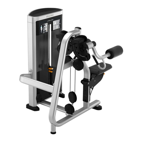
Precor HANDBOEK EFX 556i User manual
Precor
Precor Resolute RSL 504 User manual
Popular Elliptical Trainer manuals by other brands

Bonn Germany
Bonn Germany Concept 2.2 user manual
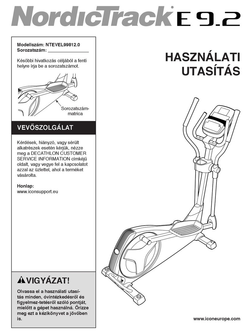
NordicTrack
NordicTrack E 9.2 Elliptical HASZNALATI UTASITAS

Vision Fitness
Vision Fitness X6600iNetTV Assembly guide

Matrix
Matrix MX-A5x owner's manual

SportsArt Fitness
SportsArt Fitness ECO-NATURAL Elite E874 owner's manual

Sears
Sears FREE SPIRIT C249 30737 0 owner's manual
