Premier 580 COUPLING Operating manual

Document #10006328
Installation, Inspection, Operation
& Maintenance Guide
THE FIRST NAME IN QUALITY COUPLINGS
IMPORTANT
Read these instructions completely before installing, using or
attempting to repair this product. If you have any questions,
call Premier at (800) 255-5387 or (503) 234-9202
MODEL 580 COUPLING PART #10001193
MODEL 580J COUPLING PART #10001196

SELECTING THE RIGHT EQUIPMENT
Whatever your application, selecting the proper equipment for the job is very important. Proper selection along with regular inspection
and maintenance will help keep operating costs minimal while providing long life to each component. Below are general guidelines for
selecting Premier Coupling and Drawbar Eyes. If you feel that your application is unique, please give Premier a call so that we may help
you through the selection process.
Follow these four steps to ensure proper selection of Premier Couplings and Drawbar Eyes.
Page 2 1-800-255-5387 • www.premier-mfg.comPREMIER MANUFACTURING
For “Double Trailer” configurations, only the rear trailer is considered when selecting
your Premier Coupling or Drawbar Eye. In this example, a Coupling and Drawbar Eye with
a “Gross Trailer Weight” rating of 40,000 lbs. (18,143 kg) would be the minimum rating
acceptable for normal, over-the-road applications (see Tongue Weight section below).
For “Triple Trailers”, only the two most rearward trailers are considered in selecting
your Premier Coupling or Drawbar Eye. In this example, a Coupling and Drawbar Eye
with a “Gross Trailer Weight” rating of 80,000 lbs (36,287 kg) would be the minimum
acceptable for normal, over-the-road applications. (See Tongue Weight section below).
STEP 1:
Determine “Gross
Trailer(s) Weight”
(GVWR(s) of towed trailers)
STEP 2:
Determine “Tongue
Weight Capacity”
(Maximum occurring
tongue weight)
STEP 3:
Add Margin of Safety
(Dependent upon your
equipment and operating
environment)
STEP 4:
Browse Premier
Product Catalog
(Based on Steps 1-3)
STEP 1: Determine “Gross Trailer(s) Weight”
“Gross Trailer(s) Weight” is usually determined by the Gross Vehicle Weight Rating (GVWR). This information is attached to the trailer by
the trailer manufacturer.
STEP 3: Consider Operating Conditions and Environments
Environments such as rough uneven roads or off-road use can dramatically increase shock loads to both drawbar eyes and couplings. In
general, increasing the “Gross Trailer Weight” (Step 1:) and “Tongue Weight Capacity” (Step 2:) by a minimum of 25% will be sufficient
for many applications. Even if an application is used off-road occasionally, the minimum increase necessary for Gross Trailer and Tongue
Weight is 25%. Certain types of equipment and/or operating practices can also dramatically increase loads through equipment binding
and/or improper loading practices. Of special concern is high tongue weight. However, each application is unique and every environment
different, therefore your application may require more than 25%.
Once both “Gross Trailers(s) Weight” (Step 1:) and “Tongue Weight Capacity” (Step 2:) have been determined, evaluate your operating
conditions and apply an appropriate margin of safety.
STEP 4: Browse Premier Product Catalog
Browse the Premier Product Catalog and refer to the “Specifications” section of each product. Be sure to review the “Understanding
Premier Load Specifications” sections and “Coupling to Drawbar Eye Cross-Reference” sheet on the next couple of pages.
STEP 2: Determine “Tongue Weight Capacity”
“Tongue Weight Capacity” is the maximum expected weight at the drawbar eye.
If a hinged drawbar is used, the maximum weight will be approximately 1/2 the
overall drawbar weight. If a non-hinged drawbar is used and the actual tongue
weight is not known, you can approximate the weight by multiplying the GVWR
of the towed trailer by 15%. However, each application is unique and the best
practice is to weigh the tongue when the trailer is loaded to GVWR.
Double Trailer Configuration
Triple Trailer Configuration
Example only, each application may vary and should be considered unique.

SAMPLE ONLY
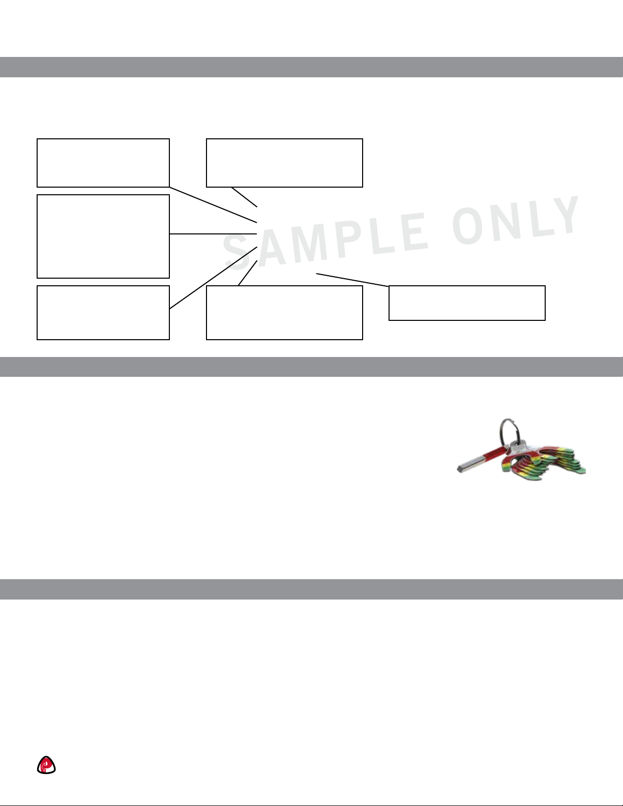
Maximum Gross Trailer Weight:
Maximum Tongue Weight:
Ultimate Latch/Upward Vertical Capacity:
Maximum Eye X-Section:
Minimum Eye Opening:
Unit Weight:
30,000 lbs.
4,500 lbs.
5,000 lbs.
1 13/16 in.
2 in.
12.6 lbs.
(13,607 kg)
(2,041 kg)
(2,267 kg)
(46 mm)
(51 mm)
(5.7 kg)
Understanding Premier Load Specifications
Each Premier product undergoes extensive design and testing prior to being introduced. We use the latest in Computer Aided Design and
Analysis Software as well as physical destructive tests. Premier’s published load specifications are the maximum load a given product or
part will withstand without failure. Premier’s testing procedures closely follow the Society of Automotive Engineers (SAE) guidelines of
Recommended Practice for testing Couplings and Drawbar Eyes (SAE J847 & J849).
SELECTING THE RIGHT EQUIPMENT
Maximum load on latch or
upper coupling surface
containing drawbar eye.
Latches and upper coupling
surfaces are not designed for
sustained load at this stated
capacity.
Maximum occurring tongue
weight. Static as well as
dynamic loads.
Weight of Trailer(s) being towed
(see “Selecting Premier Couplings
& Drawbar Eyes”).
The largest x-section in
eyelet portion of eye. Used to
determine compatibility
with coupling.
Minimum inside diameter
of eyelet portion of eye. Used to
determine compatibility with
coupling.
Weight of unit or pair of
units without accessories.
Page 3 1-800-255-5387 • www.premier-mfg.comPREMIER MANUFACTURING
Importance of Inspection and Maintenance
Whether you use Premier Jacks, Couplings, Drawbar Eyes, Hinge Assemblies or any other Premier product, regular inspection and
maintenance are essential for proper function, keeping repair costs to a minimum and above all, safe and efficient operation.
To determine wear limits, Premier created Wear Gages that help judge the useful life of couplings and
drawbar eyes (details in catalog). In accordance with Premier and the Federal Motor Carrier Safety
Regulations, these were designed to identify wear at the critical percentages of 18% and 20%, by
measuring the cross-section of coupling hooks (horn) and drawbar eye loops. 18% wear indicates that
the product should be replaced as soon as possible. At 20% wear, the product is no longer in usable
condition and must be taken out of service immediately and replaced. The latch gage bar measures the
gap space between the top of the coupling hook and the closed latch. If the 3/8” latch gage bar can
pass between this region, then the latch components should be considered worn past safe limits and replaced. Please note that these wear
gage specifications are in accordance with Premier Mfg. and the Federal Motor Carrier Safety Regulations (refer to other manufacturer’s
specifications for wear limits on their products).
Premier also provides Installation Guides for each of our major products. These help guide you through installation, inspection, routine
maintenance and part replacement. Another resource is our website at www.premier-mfg.com. Here you will find Installation Guides,
Service Guides, distributor locations, online catalogs, product information, trade show schedules and links to trucking resources.
Additional Product Resources at Your Fingertips
Customer Service: We are always here to support you. Do you need additional information or assistance? Your phone calls are greeted by
our courteous receptionist, during business hours. We have exceptional, personable Customer Service Reps for you to rely on. If you have
product questions or want to place an order, you can speak directly with one of our experienced and knowledgeable Customer Service
Representatives.
Sales Representatives: Would you like on site training or assistance? Contact one of our veteran Premier Sales Reps for more information
about product training for your staff. Or be sure to visit with them at a Trade Show (see website for schedule).
www.premier-mfg.com: Our website is an informative resource at your fingertips. In addition to our Installation and Service Guides, you
will find Territory Manager contact information, distributor locations, product specifications, product selectors, cross-reference forms,
digital product catalog, trade show schedule, and links to trucking resources.

Page 4 1-800-255-5387 • www.premier-mfg.comPREMIER MANUFACTURING
Model 580 / 580J Coupling
Specifications and Load Capacities
580 Standard Installation Drawing
580J Standard Installation Drawing
Gross Trailer Weight:
Maximum Tongue Weight:
Ultimate Latch Capacity:
Maximum Eye X-Section:
Minimum Eye Opening:
Unit Weight:
Gross Trailer Weight:
Maximum Tongue Weight:
Ultimate Latch Capacity:
Maximum Eye X-Section:
Minimum Eye Opening:
Unit Weight:
Model 580 Model 580J
70,000 lbs. (31,751 kg)
14,000 lbs. (6,350 kg)
30,000 lbs. (13,607 kg)
1 13/16 in. (46 mm)
2 in. (51 mm)
21.3 lbs. (9.7 kg)
90,000 lbs. (40,823 kg)
18,000 lbs. (8,164 kg)
30,000 lbs. (13,607 kg)
1 13/16 in. (46 mm)
2 3/8 in. (60 mm)
25.3 lbs. (11.5 kg)
580
PREMIER
6 1/2
8 1/4
11/16
6 19/32
8 29/32
6 27/32
5 1/4
1 3/8
3
1
5 3/8
5 1/81 3/4
4 X
25/32
2 11/16
4 7/16
11/32
1 29/32
580J
PREMIER
1 1/8
1 5/8
1 3/8
1 1/2
5 5/8
6 1/2
7 1/2
5 1/4
2 1/4
6 X
25/32
7
4 13/16
3/4
2
9 3/8
2 3/8
5 9/32
9 3/8
2 15/16
7 9/32
2 1/8
SAFETY WARNING
This product is designed for towing under normal conditions within the stated gross trailer weight.
Do not overload or abuse this product. Overloading or abuse may lead to property damage, severe injury, or death.

Replacement Part Information
Model 580 / 580J Coupling
Accessories
Parts
Optional Accessories:
580:
- 14008 Wear Gage (#10000056) (1 3/4in.): To determine hook wear limits.
- 14026 Latch Gage (#10000071): To determine latch gap limit.
- 507 Bolt Kit (#10000154): Four 3/4-10 x 2 3/4 in. grade-8 bolts and 3/4-10 grade-C locknuts.
580J:
- 14026 Latch Gage (#10000071): To determine latch gap limit.
- 503 Bolt Kit (#10000151): Six 3/4-10 x 2 1/2 in. grade-8 bolts and 3/4-10 grade-C locknuts.
Coupling only:
- 580 Coupling (#10001193)
- 580J Coupling (#10001196)
Page 5 1-800-255-5387 • www.premier-mfg.comPREMIER MANUFACTURING
*581: Handle Assembly
580RK Parts Kit (#10001199) Includes:
Model # Part # Description
266 10000290 Spring
375A 10000347 Locknut
387 10000350 Locknut
*581 10004793 Handle Assembly
581A 10001201 Handle
581BB 10001203 Clip & Cable
581C 10001206 Bushing
Model # Part # Description
582 10000371 Latch
582A 10000372 Spring
583 10001038 Pawl
584 10001215 Bolt
585 10001216 Spring

Page 6 1-800-255-5387 • www.premier-mfg.comPREMIER MANUFACTURING
Installation
Inspection/Operation/Maintenance
Model 580 / 580J Coupling
The 580/580J Coupling is only to be used and maintained with Premier parts listed in the Replacement Part Information section.
Any substitution or use of non-Premier parts in a 580/580J Coupling will VOID ALL PRODUCT WARRANTY.
Installation Procedure:
1. The 580/580J Coupling must be installed to comply with the Federal Motor Carrier Safety Regulations. Specifically, Section
393.70, Paragraph C: “Towing of Full Trailers.” Prior to install or operation, consult with local, State and Federal agencies, as
there may be additional applicable laws governing installation and use of this product.
2. Make certain that the cross member the 580/580J Coupling is to be mounted on is of sufficient strength to withstand the
load rating of the coupling.
3. Using the Standard Installation Drawing, measure and layout the cross member and then drill the holes for the mounting
bolts.
4. Mount the 580 Coupling using either Premier’s 507 Bolt Kit and provided torque value, or four other 3/4” grade-8 bolts and
grade-C locknuts. Mount the 580J Coupling using either Premier’s 503 Bolt Kit and provided torque value, or six other 3/4”
grade-8 bolts and grade-C locknuts. Only use new fasteners when mounting couplings or drawbar eyes and torque to SAE
specifications.
5. Once mounted, check the latch components for proper operation and clearances (see the Inspection/Operation/Maintenance
section for opening and closing the latch). If the operation of the latch components is sticky, lubricate all rotation points
(see the Inspection/Operation/Maintenance section for the lubrication instructions). Work the latch assembly several times to
distribute the lubricant evenly and remove any excess with a rag. Do not apply lubricant to the pintle/hook or saddle area of
the 580/580J Coupling.
6. An “IMPORTANT WARNINGS!” sticker was enclosed. This must be attached to the coupling or cross member and be visible
for the end user to read.
Inspection and Maintenance:
1. Visually inspect the coupling body and latch components for cracks, impact damage and/or deformation before each and
every use. Do NOT use if any of these conditions exist.
2. Check the gap between the 582 Latch and the top of the pintle/hook before each and every use. Lift up on the latch to
remove any free play and measure the gap. A gap of 3/8” or more means the coupling must be taken out of service and
repaired or replaced.
3. If the wear area on the pintle/hook has worn 20% or more from its original cross-section, the coupling is considered out-of-
service and must NOT be used.
4. Lubrication of the latch components must be performed at 90-day intervals or sooner depending on the operating environ-
ment. Lubricate the latch components with a spray-type lubricant to evenly coat all rotation points and use a pump-style oil
can at the oiler fittings on both ends of the 581A Handle. Rotate each latch component several times to evenly distribute the
lubricant.
5. Remove any excess lubricant with a rag. Do not apply lubricant to the pintle/hook or saddle area of the coupling.
6. Never weld on any Premier part in order to repair damaged or worn areas. Field and/or shop welds are inadequate and may
further weaken the coupling.
7. WARNING: Other inspection and maintenance procedures are also required prior to the operation of combination vehicles.
Consult and follow all Federal Motor Carrier Safety Regulations as well as local, state and federal guidelines.

Page 7 1-800-255-5387 • www.premier-mfg.comPREMIER MANUFACTURING
Inspection/Operation/Maintenance
Model 580 / 580J Coupling
Operation:
OPENING Coupling Latch:
1. Remove the 581BB Clip from the 581C Bushing on the 581A Handle.
2. Grasp the 581A Handle and firmly pull outward, away from the coupling body.
3. While holding the 581A Handle in this position, rotate the handle clockwise until full rotational travel is reached. The 582
Latch will open by rotating upward.
4. Release the 581A Handle and the 580/580J Coupling is now open and ready to be coupled or uncoupled with a drawbar eye.
CLOSING Coupling Latch:
5. With an open palm, push downward on the top of the 582 Latch until it rotates all the way down and is stopped by contacting
the top of the pintle on the 580/580J Coupling body.
6. Visually verify that the latch components have reset to their locked closed position. The 581A Handle should be rotated back
to its latched closed position and the ring groove on the 581C Bushing should now be exposed out the side of the coupling
body.
7. Place the 581BB Clip over the exposed ring groove on the 581C Bushing. If the ring groove is not exposed enough for the
clip to fit, the 580/580JCoupling is not locked closed. Do not operate the coupling without the clip securely residing in the
groove.
8. Verify that the 582 Latch is securely closed by grasping the latch and attempting to lift it upward. THE LATCH SHOULD
NOT OPEN!If the latch does not stay closed, do not use it until it has been repaired or replaced.
9. This product is designed to be operated within its free rotation limits. It is the responsibility of the vehicle designer/end user
to ensure that these limits are not exceeded (do not bind-up/jackknife).
10. WARNING: Prior to towing, make certain that adequately rated safety chains have been properly connected.
IMPORTANT GUIDELINES that apply to all Premier Non-Air Couplings
- Do not weld on any coupling assembly
- Always use Grade-8 fasteners properly torqued
- Do not apply lubricants to the coupling hook
- Clean & inspect coupling for damage & excessive wear prior to each and every use
- Lubricate all coupling components at a minimum of 90 day intervals
- Do not bind-up (Jackknife) any application as stresses can cause damage to products or components, resulting in failure and
detachment of the trailer while in use

Page 8 1-800-255-5387 • www.premier-mfg.comPREMIER MANUFACTURING
ATTENTION!
End Users must read and follow this information.
DISTRIBUTORS & OEM’S: Please ensure that your customers are
made aware of the following information on this page.
1. VERIFY THAT BOTH COUPLING’S AND DRAWBAR EYE’S RATED CAPACITIES MEET YOUR APPLICATION(S)
REQUIREMENTS.
2. DO NOT OVERLOAD COUPLING OR DRAWBAR EYE.
3. INSPECT COUPLING, LATCH AND DRAWBAR EYE FOR CRACKS, BENDING DAMAGE OR EXCESSIVE WEAR.
DO NOT USE IF ANY OF THESE CONDITIONS EXIST!
4. CHECK FOR GAP BETWEEN CLOSED LATCH AND TOP OF HORN OR COUPLING BALL.
DO NOT USE IF GAP IS 3/8 IN. OR MORE.
5. MAKE SURE COUPLING IS LATCHED AND THAT LATCH WILL NOT OPEN.
6. PRIOR TO USE, ALWAYS CONNECT SAFETY CHAINS OF ADEQUATE STRENGTH FOR LOAD(S) BEING TOWED.
7. DO NOT BIND-UP (JACKKNIFE) ANY APPLICATION AS STRESSES CAN CAUSE DAMAGE TO THE COUPLING,
DRAWBAR EYE, OTHER COMPONENTS OR ANY COMBINATION OF THEM. JACKKNIFING MAY RESULT IN
FAILURE OF PRODUCTS OR COMPONENTS, RESULTING IN DETACHMENT OF THE TRAILER WHILE IN USE.
8. DO NOT APPLY LUBRICANTS TO THE COUPLING HOOK OR DRAWBAR EYE LOOP, AS THEY CAN COVER UP
POSSIBLE DAMAGE AND ACCELERATE WEAR.
9. ALWAYS ABIDE BY ALL APPLICABLE STATE AND FEDERAL REGULATIONS GOVERNING SAFE AND PROPER
TRANSPORTATION.
10. NEVER STRIKE ANY OF THESE COMPONENTS WITH A HAMMER OR ANY OTHER DEVICE.
11. ALWAYS VERIFY PROPER OPERATION OF LATCHING SYSTEM AND COUPLING COMPONENTS PRIOR TO DRIVE OFF.
12. NEVER USE A COUPLING THAT YOU DO NOT FULLY UNDERSTAND HOW TO PROPERLY OPERATE AND VERIFY
SECURE LATCHING OF.
13. NEVER REPLACE ANY PART IN ANY OF PREMIER’S ASSEMBLIES WITH NON-PREMIER COMPONENTS. DOING SO
WILL VOID ALL WARRANTY AND POTENTIALLY COMPROMISE THE UNIT’S INTEGRITY, WHICH COULD RESULT IN
PROPERTY DAMAGE, SERIOUS INJURY, OR DEATH.

PREMIER MANUFACTURING
THE FIRST NAME IN QUALITY COUPLINGS
800-255-5387 (503)234-9202
www.premier-mfg.com
WARNING!
This envelope contains important instructions
AND MUST REMAIN ATTACHED TO THIS
COUPLING. It may be removed only by the End
User or by an Original Equipment Manufacturer
who preserves this envelope and instructions and
provides it to the end user.
Model 580 / 580J Coupling
1-800-255-5387 • www.premier-mfg.comPREMIER MANUFACTURING Page 9
WARRANTY: We warrant all Premier products to be free from defects in material or workmanship for one year. We will
repair or replace, at our option, any Premier product which our examination reveals to be defective, provided that the
product is returned to our factory, at Tualatin, Oregon transportation prepaid, within one year of purchase by the first retail
purchaser. Our warranty does not extend to products which have been subject to misuse, neglect, improper installation,
maintenance or application, nor does our warranty extend to products which have been repaired or altered outside of
3UHPLHU·V facility unless the repair or alteration has been expressly authorized in writing by Premier. This warranty is in
lieu of all other warranties, express or implied, and excludes warranties of merchantability, fitness for a particular purpose and
otherwise, and in no event will Premier be liable for incidental, special, contingent or consequential damages.
DISCLAIMER: Although great care has been taken to ensure accurate information throughout this document, Premier
Manufacturing must reserve the right to alter any information contained within. These changes include but are not limited to:
Dimensional changes, load capacity and availability of any part or assembly.
© 2009 Premier Manufacturing
All rights reserved. Any reproduction of the photographic images or any other portion of this document, including but not
limited to the photocopying, or retention and/or storage in a retrieval system of any kind, is strictly prohibited without prior
express written permission from Premier Manufacturing.
This manual suits for next models
3
Table of contents
Other Premier Industrial Equipment manuals

Premier
Premier 127 Operating manual

Premier
Premier 470 Operating manual

Premier
Premier 240 COUPLING Operating manual

Premier
Premier 2200PK-ELL Instruction Manual

Premier
Premier 2200ELL Operating manual

Premier
Premier 2200 Operating manual

Premier
Premier 2200 Instruction Manual

Premier
Premier 270PK Instruction Manual

Premier
Premier 200 Operating manual

Premier
Premier 890L Instruction Manual