1-800-255-5387 • www.premier-mfg.com
PREMIER MANUFACTURING COMPANY Page2
IMPORTANT NOTES TO CLEAN,
INSPECT & LUBRICATE:
► UseonlygenuinePREMIERreplacementparts
onanyrepairs.Useofotherparts,whichcan
havedifferentspecificationsortolerances,may
failtoalertyoutonon-obviousdamagetothe
hitchwhichcanleadtohitchfailure.
► Allbodyholes,partholesandpinsneedto
bethoroughlycleanedandlubricatedwitha
heavygreasebeforethepartsarereassembled.
DONOTLUBRICATEPINTLEHOOKWEAR
SURFACE.
► Clean,inspectandlubricatelatchcomponents
every90daysorsoonerifrequiredbythe
operatingenvironment.
► Cleanandinspectthecouplingfordamageand
excessivewearpriortoeachandeveryuse.
► Donotover-tightenfastenersasthismaycause
damage.
ASSEMBLY
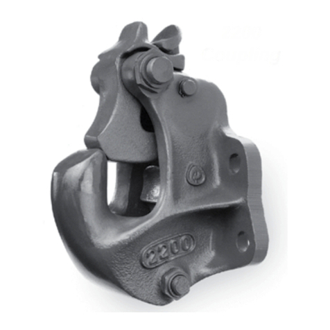
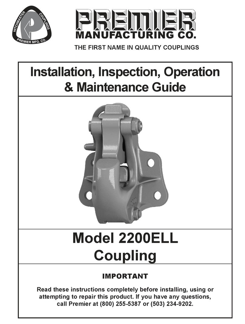
Priortoassembly,placethe2072ELLatchintothe
couplingbodyaligningitwiththeupperbodyholes
andslidethe2071ELBoltthroughtheholes.Rotate
thelatchtotheclosedpositionandmeasurethe
gapbetweenthelatchandtopofthepintle.Ifthe
gapis3/8”ormore,thecouplingbodyisdamaged
andmustbereplaced.Ifthegapislessthan3/8”,
removethebolt,latchandbushingandbegin
assembly.
1) IFyouarereplacingthe279Shoeandits
components,thenfollowtheinstructionsbelow:
Otherwisecontinueonto#2.
Placethe266Springoverthenippleonthe
279Shoe.Insertasassembledthroughthe
openingatthetopofthecouplingandinto
thecavityatthebottom.The266Spring
shouldseatintotheconcavecavity,which
residesbelowthepintlebase.The266Spring
mustbeslightlycompressedtoalignthe279
Shoeholewiththebottombodyhole.From
theleftsideofthebody,insertthe274Bolt
(lefttoright)intothebottomcouplingbody
holeandsecureontherightsidewith274A
Locknut.Makecertainthatoneoftheflatsof
the274Boltheadisflushwiththeflatonthe
bodysidewall.Rotatethe279Shoetoverify
properspringtension.
2) Takethe2074ELPin,withthegreasezerkfitting
positionedtowardstheright,andinsertitinto
therightsidebodyhole,allowingapproximately
1/2”toextendpasttherightsideinteriorwall
surface.Placeoneofthe373BSpacersontothe
extendingendofthe2074ELPin,withinthebody
cavity.
3) Positionthe2073ELLatchLockintothebody,
adjacenttothe373BSpacer.Alignthehole,
thenslidethe2074ELPinthroughtotheleft,until
flushwiththeleftsideofthe2073ELLatchLock.
4) Holdthe2073ASpringsothatthestraightleg
ispointingupwardontheleftsideofthespring
andthehookedlegisontheright.Placethe
springontheleftsideofthe2073ELLatchLock,
aligningitwiththebodyholeontheleftside
andthe2074ELPinontheright.Thestraight
springlegshouldbealongthetopledge,pointing
towardyou.
5) Rotatethe2073ELLatchLockforwardtoward
youandcapturethehookedendofthespring
withthefrontpartofthecatchledgeonthe
bottomofthe2073ELLatchLock.Keepingthe
2073ELLatchLockintheforwardposition,push
the2074ELPinthroughthe2073ASpringand
outtheleftsideofthecouplingbody.
6) Closelyexaminetheleftside’sinteriorbody
sidewall,adjacenttothe2073ASpring,and
locatethecatchledgerunningata45degree
angle.Thisiswherethestraightlegofthespring
needstobeplaced.Usingaflatbladedscrew
driver,prythestraightlegawayfromthetop
interiorledgeofthecouplingandrotateituntilit
engageswiththecatchledge.PleaseNote:Do
notover-stressthe2073ASpringwhenengaging
eitherendandalsoMAKECERTAINboththe
straightendandhookedendarecompletely
engagedwiththecatchsitelocations(seeImage
#3).
7) Rotatethe2073ELLatchLockbackwards,tothe
openedposition.Ifspringisinstalledcorrectly,
smoothincreasingspringresistanceshouldbe
feltwhenrotated.Ifnoresistanceorbinding
isfelt,thespringand/orpartsarenotinstalled
correctly.

