Page 2 1-800-255-5387 • www.premier-mfg.comPREMIER MANUFACTURING
3. Place 695 Spring alongside 693 Pawl (one leg nests in groove on side of pawl). With 695 Spring to the right, install the 693
Pawl and spring through the bottom of the body. Make sure that the leg of the 695 Spring nests in groove inside body.
4. Install 691 Handle, locating tapers on pin portion with tapers inside 693 Pawl. Slide 691C Bushing over threaded end of
691 Handle and into body (for 690R the 691CR clip groove must be furthest from body) and secure entire assembly with the
387 Nut.
5. Install 266 Spring. Nest one end of 266 Spring in the recessed pocket of 693L or 693R Pawl, and the other end in the
recessed pocket of the coupling body.
6. While holding the spring in position, rotate 691 Handle clockwise (counter-clockwise for 690R) to the open position and
engage lug 693 Pawl with lug on internal body sidewall (right side). This will hold the handle in the open position. Turn entire
body over and place on mounting base (nose pointing away from you).
7. Position 692 Pintle Hook into body and install 294 Bolt, from right to left, securing the 692 Pintle Hook in position.
8. Align one of the flats on the 294 Bolt head with the rasied stop on the coupling body. Make certain the bolt head is flush with
the coupling body. It’s possible the hole will need to be minorly chamfered, or the bolt stop ground or filed for the 294 Bolt
head to sit completly flush.
9. Remove any grease on the threads of the 294 Bolt prior to installing 297 Locknut. Torque the 297 Locknut to 50 ft-lbs
(Do not exceed 50 ft-lbs of torque).
10. Coupling is now assembled and should be opened and closed several times, testing for smooth and correct operation. Do not
use the coupling if it does not close properly.
11. Lubricate latch assembly where appropriate (DO NOT LUBRICATE PINTLE HOOK WEAR SURFACE ).
WARNING: Do NOT bind-up (jackknife) any application, as stresses can cause damage to the 294 bolt, hitch, drawbar eye, other
components or any combination of them. Jackknifing may result in failure of products or components, resulting in detachment of
the trailer while in use.
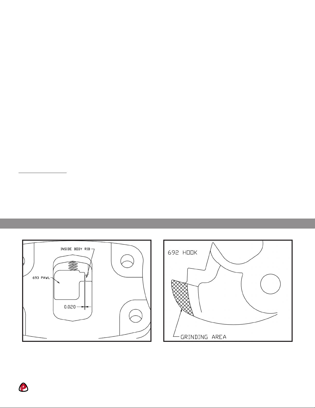
Figure 1 Figure 2
PROPER OPERATION:
• NOTE: The following is for installation of new components.
• When coupling is placed in opened position, there should exist a clearance of at least .020” between the 693 Pawl and the
inside wall of coupling body. (Figure 1)
• When coupling is placed in opened position, the 692 Hook may not fully rotate forward. If this occurs, the 692 Hook may
need light grinding for proper fit and operation. (Figure 2)


