Premium EDT-150-5191 User manual

Specifications are subject to change without notice. These products are not intended for use as critical components in life
support or nuclear systems.

MA-5191A
21-10-2021
2/ 110
1. WARNING:.......................................................................................................... 4
2. INSPECTION OF THE MATERIAL UPON RECEIPT OF THE EQUIPMENT: ................ 1
2.1 LIST OF COMPONENTS .................................................................................................... 1
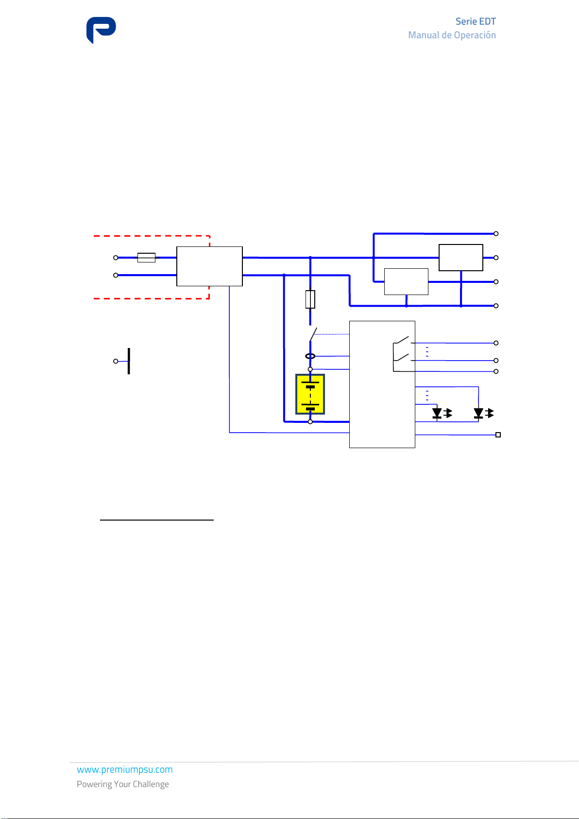
3. EDT-150-5191 SYSTEM DESCRIPTION................................................................ 2
4. CHARGER FUNCTION .......................................................................................... 4
5. FEATURES:.......................................................................................................... 6
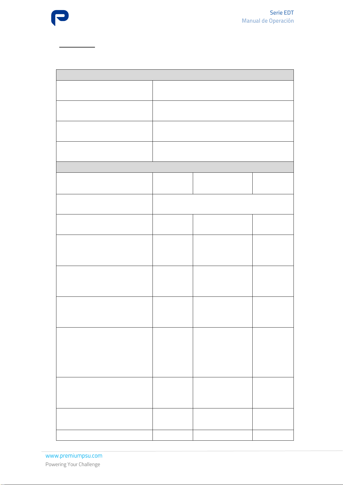
5.1 ELECTRICAL, ENVIRONMENTAL AND MECHANICAL CHARACTERISTICS: .................................. 6
5.2 ELECTRICAL BEHAVIOUR: ............................................................................................... 8
5.3 PROTECTION................................................................................................................. 8
5.4 SIGNALLING ................................................................................................................10
5.5 ALARMS.......................................................................................................................11
5.6 WIRING AND SIGNALS:..................................................................................................12
5.6.1 TERMINAL BLOCKS AND SIGNALS:...................................................................................12
5.6.2 BUTTON: .....................................................................................................................15
5.7 TEMPERATURE SENSOR .................................................................................................16
5.8 CONFIGURATION: .........................................................................................................16
5.9 COMMUNICATIONS: ......................................................................................................17
6. INSTALLATION:................................................................................................ 18
6.1 INSTALLATION REQUIREMENTS ......................................................................................20
6.2 BATTERY INSTALLATION ................................................................................................20
7. WIRING............................................................................................................ 21
7.1 ELECTRICAL MAINS AND EARTH CONNECTION:..................................................................22
7.2 OUTPUT AND BATTERY CONNECTION: ..............................................................................23
7.3 BATTERY TEMPERATURE PROBE CONNECTION:..................................................................24
7.4 ALARM RELAYS CONNECTION: ........................................................................................25
7.5 ETHERNET NETWORK WIRING CONNECTION: ....................................................................25
8. COMMISSIONING ............................................................................................. 27
9. OPERATION ...................................................................................................... 28
10. PROCESSES: ..................................................................................................... 29
10.1 ALARMS: .....................................................................................................................29
10.2 BATTERY CONSUMPTION:...............................................................................................31
10.2.1 STATE OF CHARGE: .................................................................................. 31
10.2.2 EQUIPMENT TOTALLY TURNED OFF: ........................................................ 33
10.2.3 EQUIPMENT TURNED ON AND WITHOUT MAINS INPUT:.......................... 33
10.3 CONFIGURATION: .........................................................................................................33
10.4 POWER-UP:..................................................................................................................33
10.5 VARIATION OF FLOAT VOLTAGE WITH TEMPERATURE: ........................................................34
10.6 CONNECTION AND BATTERY CHARGING: ..........................................................................36
10.7 BATTERY DISCHARGE AND DISCONNECTION: ...................................................................37
10.8 RECOVERING BATTERY: .................................................................................................37
10.9 BATTERY TEST:.............................................................................................................39
10.10 BATTERY CHANGE: ....................................................................................................40
10.11 POWER DISTRIBUTION: .............................................................................................40

MA-5191A
21-10-2021
3/ 110
11. MAINTENANCE: BATTERY REPLACEMENT: ........................................................ 41
11.1 CHARGER ....................................................................................................................41
11.2 BATTERIES ..................................................................................................................41
12. DIAGNOSTIC .................................................................................................... 43
13. STANDARD ....................................................................................................... 45
14. LABELLING: ...................................................................................................... 47
15. TRANSPORT, RECEIPT AND STORAGE INSTRUCTIONS...................................... 48
15.1 TRANSPORT .................................................................................................................48
15.1.1 PACKAGING:............................................................................................ 48
15.1.2 HANDLING:.............................................................................................. 49
15.1.3 TRANSPORT:............................................................................................ 49
15.2 RECEIPT:.....................................................................................................................50
15.3 STORAGE: ...................................................................................................................52
16. ENVIRONMENTAL INFORMATION: .................................................................... 53
17. GUARANTEE...................................................................................................... 54
18. ANNEXES:......................................................................................................... 55
18.1 ANNEX A: PERFORMANCE CURVES FOR EDT-150-5191: ................................................................55

MA-5191A
21-10-2021
4/ 110
1. WARNING:
To prevent accidents and injuries, the following safety instructions for handling our equipment must
be observed.
For your own safety, you must have read and understood the relevant safety instructions before working
with the equipment.
Keep the safety instructions in a place accessible to all persons working with the equipment so that
they can refer to them.
Our equipment should only be handled by experienced and appropriately authorised personnel
.
Error messages. These must be observed under all circumstances; the cause must be located and
eliminated.
Warnings regarding sources of danger. When handling or accessing the inside of the device,
conductive parts represent a potential hazard.
Voltage in general. The device operates with a maximum voltage of 230 VAC. This voltage is
dangerous and can cause personal injury in case of contact with conductive parts of the equipment.
The conductive parts inside the equipment are considered especially hazardous areas. These may
include: various soldering points, printed conductors, terminals for mains connection, relay contacts,
etc. Before opening the device, disconnect the mains voltage from all poles.
External voltages. When disconnecting a piece of equipment, it is also necessary to consider possible
external voltages and feedback of the powered equipment.
Fuses. Only original fuses should be used, in accordance with the equipment.
Use in accordance with the intended purpose. The device must only be used for its intended
purpose. Any use not in accordance with the purpose is prohibited. PREMIUM S.A. cannot be held liable
for damages resulting from improper use. In such a case, the user must assume sole responsibility for
the risk. Use in accordance with the intended purpose is defined in the documentation. The device may
only be exposed to permissible environmental influences. These are specified in the technical data of
the equipment.
Prohibition of arbitrary modifications. The equipment must not be modified with respect to
construction or safety technology without our express consent. Any modification excludes a liability on
our part for damage caused by the modification. In particular, all repair work, soldering on printed
circuit boards and the replacement of components, modules and printed circuit boards are forbidden
without the express authorisation of PREMIUM S.A. If spare parts are used, only original PREMIUM
S.A. parts must be used. PREMIUM S.A. declines any liability resulting from an inadequate, negligent
or incorrect installation of the equipment, or from an incorrect connection of the equipment.
Due to the policy of continuous improvement, the content of this manual is subject to change without
notice.

2. INSPECTION OF THE MATERIAL UPON RECEIPT OF THE EQUIPMENT:
Upon receipt of the equipment, a visual inspection of the assembly should be carried out to
detect any defects due to transport. Then check that all the items listed in 1.1 have been
correctly supplied.
2.1.1.1LIST OF COMPONENTS
The product consists of the following parts:
•Charger EDT-150-5191
•4-pole female connector for mains input
•8-pole female connector for output and battery
•5-pole female connector for alarms
•Temperature sensor with cables and connector
Note: Verification and warranty certificates: These remain electronically stored at the
manufacturer and will only be sent upon request.

MA-5191A
21-10-2021
2 / 110
3. EDT-150-5191 SYSTEM DESCRIPTION
The EDT-150-5191 is a 12V battery rectifier-charger capable of managing the charging of lead
batteries up to 40Ah capacity.
The total power it can deliver without the aid of the battery is 150W permanently, 275W for
25 seconds and 300W for 10 seconds every minute. If the battery is connected and in good
condition, the output can provide a total power of 300W for 60 seconds.
The input voltage is 230VAC.
Figure 1. View EDT-150-5191
The charger-rectifier architecture used has the battery connected directly to the output, as can
be seen in the following figure:
Figure 2. Block diagram.
Phase
+12V (Native)
Neutral
Earth
0V
AC / DC
Control V-I
2kV insulation
BATTERIES
Chassis
DC / DC
DC / DC
+48V (Motors)
+48V (40W)
(communications)

MA-5191A
21-10-2021
3 / 110
The function of this equipment is that of an uninterrupted power supply system, the mission
of which is to keep the charges powered at all times. For this, you must:
-Provide an uninterrupted power supply at its outputs and within the specified range.
-Protect against normal operating situations (power-up, punctual overloads, etc.) as
well as abnormal situations (short-circuits and permanent overloads at its output,
etc.).
-Carry out proper treatment of the batteries that are necessary for its operation:
-The aim is to maximise their life and minimise their charging time.
-Implement protections against improper operations that could damage them
(deep discharges and float voltage adjustment with temperature).
The battery is charged using the UI method, i.e. at constant voltage and limited current. When
the battery is fully charged, these chargers keep it in float, supplying a small maintenance
current requested by the battery. When the battery has been fully or partially discharged after
a mains failure, the chargers modify the battery/output voltage to replenish the discharged
energy in the shortest possible time by increasing the battery/output voltage but taking care
to limit the maximum value of the charging current received by the battery. Both the
battery/output voltage under charge and the maximum charging current are parameterisable
values.
Unlike other equipment, this equipment incorporates a battery status check system that
measures the useful capacity of the battery.
These items also incorporate a high-precision temperature sensor that allows optimal charging
of the battery, depending on its temperature.
In addition, the equipment includes four alarm signals by means of potential-free contacts
(mains failure, urgent failure, non-urgent failure and end of autonomy). On the front there are
8 LED indicators: 3 green "Equipment running", "Charging status" and "Battery test running";
one yellow "Battery discharge"; and 4 red "Input power failure", "Output anomaly", "Battery
anomaly" and "Equipment anomaly".
As mentioned above, this equipment has a 12V output connected to a battery. Through this
output, the equipment can supply 150W permanently without the aid of the battery, 275W for
25 seconds and 300W for 10 seconds every minute. If the battery is connected and in good
condition, the output can provide a total power of 300W for 60 seconds.
In addition, this equipment also has two non-isolated DC/DC converters with 48V output.
•The one corresponding to output 2 indicated as "48V (40W)" is a 40W
converter. It is optimised for powering communications equipment.
•The one corresponding with output 3 indicated as "48V" is a 150W converter
that can supply 200W for 10s every minute (depending on the charge on the
other outputs). This converter is optimised for motor power supply.

MA-5191A
21-10-2021
4 / 110
This equipment performs a priority management of the power demands at its outputs. Due to
the fact that the sum of the permanent and peak power available at its outputs could exceed
the maximum values of the equipment if they were demanded simultaneously, the equipment
has a priority management of the power available at the outputs.
For this purpose, it gives priority to the power supplied by the 12V output and that of the
converter intended for communications over the power supplied by the converter intended for
motor power supply.
The following figure shows the block diagram of this equipment:
Figure 3. Block diagram EDT-150-5191
4. CHARGER FUNCTION
This equipment is powered at an input voltage of 230VAC (range 184-265Vac), acting as
switched AC/DC converters, with galvanic isolation between input and output (up to 2kV at
industrial frequency and 5kV lightning impulse).
The power stage transforms the energy coming from the mains into a stabilised DC voltage,
providing isolation between input and output.
The equipment control is responsible for keeping the output voltages regulated, charging
the battery and monitoring other parameters to ensure that they are within the set margins.
It is also responsible for signalling, alarms and Ethernet communications.
The equipment has two non-isolated DC/DC converters that receive as input the output
connected to the battery, generating two 48V outputs for powering communications equipment
and motors.
Phase
+12Vdc (Native)
Signalling
Local
Neutral
Earth
+Input
Chassis
AlarmsFail
+48Vdc
(Motors)
0V
Control
DC / DC
AC / DC
2kV insulation
Ethernet
DC / DC
+48Vdc (40W)
(communications)

MA-5191A
21-10-2021
5 / 110
In the event of a failure in the AC mains supply, the control continues to be powered from
the batteries. When it reaches a discharge limit value, a contact in series with the battery is
opened. This prevents it from being damaged by a deep discharge. When this contact is
opened, the charger will be disconnected and will remain so until the AC mains voltage returns
or a reconnection from the battery is forced by means of the button enabled for this purpose.
Figure 4. Charger EDT-150-5191
This equipment has a battery status control system (battery test). The condition of the
batteries is monitored periodically. In addition, this measure is always performed when the
batteries are floating.
This test consists of discharging the battery through the charges connected to the output of
the equipment. The objective is to verify that the batteries maintain a minimum energy storage
capacity for the application.
The battery is charged using the UI method, i.e. at constant voltage (or fast charge) and
limited current. When the battery is fully charged, these chargers keep it in float, supplying a
small maintenance current. When the battery has been fully or partially discharged after a
mains failure, the chargers modify the output voltage so that the current received by the
battery is limited to a parameterisable charging current.

MA-5191A
21-10-2021
6 / 110
5. FEATURES:
5.1.1.1ELECTRICAL, ENVIRONMENTAL AND MECHANICAL CHARACTERISTICS:
AC INPUT FEATURES
Mains input voltage
230Vac
Mains voltage range
-20%...+15%
Mains frequency range
47...63Hz
Starting current
< 12A
DC OUTPUT FEATURES
OUTPUT 1
(native)
OUTPUT 2
(communications)
OUTPUT 3
(motors)
Battery voltage
12 V
Nominal output voltage
13.62 V
48 V
48 V
Voltage range:
No mains or limiting the charge
current
9.6...15 V
47...49 V
47...49 V
Line regulation:
Output variation for the input
voltage range.
<0.1%
<0.1%
<0.1%
Maximum permanent current:
Output 12V+battery charge
(Vout1=9.6V)
15.7 A
0.83 A
3.2 A
Maximum permanent power of
the outputs:
They may not be simultaneous
and are limited to the maximum
total of the equipment.
150 W
40 W
150 W
Total peak output power
(200ms):
Without battery support.
300 W
40 W
200 W
Total peak output power (10s):
Without battery support.
275 W
40 W
200 W
Total peak output power (60s):

MA-5191A
21-10-2021
7 / 110
Delivering 150W across the
charger and the rest the battery.
300 W
40 W
200 W
Curly
50mVpp
100mVpp
100mVpp
Noise (BW 20MHz)
100mVpp
200mVpp
200mVpp
Performance:
At nominal input voltage and
nominal power
>84%
(See annex with efficiency curve)
CHARGER FEATURES
Battery type
Watertight lead
Nominal battery voltage
12V
Battery capacity
38Ah
Maximum battery charging current
(parameterisable)
0 … 15A
Auto-consumption of battery at rest
< 150µA
Battery auto-consumption without AC:
< 4% Nominal power
Minimum battery voltage:
To start the battery recovery process.
4V
Temperature sensor precision
1ºC
Temperature measurement precision:
Throughout the measurement channel
3ºC
ENVIRONMENTAL CHARACTERISTICS
Operating temperature
-25…60°C
Storage temperature
-40…85°C
Relative humidity
5…90% without condensation
Cooling
Natural convection
Altitude
<1000m
Environmental requirements
RoHS according to the 2002/95/EC Directive
MECHANICAL CHARACTERISTICS
Dimensions:
Including connectors.
265.5x115x90.2mm (Width x Height x
Depth)
Weight:
<1.7kg
Protection level
IP20

MA-5191A
21-10-2021
8 / 110
Figure 5. Dimensions and wiring EDT-150-5191
5.1.1.2ELECTRICAL BEHAVIOUR:
The following groups have been defined to specify the dielectric strength:
GROUP
SIGNAL
G1
AC input
G2
Alarms
G3
Temperature sensor + 48V Output + Battery + NC
G4
Ethernet Port
G5
Earth
The dielectric strength between groups is as follows:
Test poles
Lightning
impulse
1.2/50µs
Dielectric
strength
50Hz 1 minute
Isolation with
impulse
Pole-1
Pole-2
G1
G2 + G3 + G4 + G5
± 5 kV
2 kVac
± 5 kV
G2
G1 + G3 + G4 + G5
± 2 kV
1 kVac
± 2 kV
G3
G1 + G5
(G2 + G4 together without
connecting to G5)
± 5 kV
2 kVac
± 5 kV
G4
G1 + G2 + G3 + G5
± 2 kV
1 kVac
± 2 kV
5.1.1.3PROTECTION
The mains input is protected by a fuse dimensioned for extreme cases in which the equipment
could break internally and require specialised technical service.
The equipment is protected as follows:
J1
J3
J4
J2
ETH

MA-5191A
21-10-2021
9 / 110
•Protection against mains overvoltage via varistors.
•Protection against secondary overvoltage.
•Protection against overload and short-circuit of outputs via current limitation.
The battery has various degrees of protection:
•Electronic limitation of the charging current.
•Short-circuit protection via a self-rearming fuse.
•Protection against deep discharge of the battery via a relay in series with the battery, so
that its disconnection is guaranteed when the terminal voltage reaches the pre-set
minimum value.
•Protection against battery polarity inversion.

MA-5191A
21-10-2021
10 / 110
5.1.1.4SIGNALLING
The module has eight LEDs on the front for local signalling:
LED name
Colour
Mode
Signal
Equipment running
Green
Fixed light
Charger running
Charging status
Green
Fixed light
Battery charging float mode
Flashing
Battery charging constant voltage mode
Battery test running
Green
Fixed light
Battery test in progress
Battery discharge
Yellow
Fixed light
Battery discharging
Input power failure
Red
Flashing
Mains input voltage out of range
Output anomaly
Red
Flashing
Output voltage 1, 2 or 3 out of range
Battery anomaly
Red
Fixed light
Failed battery test, degraded batteries
Flashing
Battery voltage out of range
Equipment anomaly
Red
Fixed light
Battery temperature sensor error
Flashing
Internal charger error
When the charger enters IP LOCAL mode via the button, all LEDs flash at the same time.

MA-5191A
21-10-2021
11 / 110
5.1.1.5ALARMS
Four potential-free contact alarm outputs with the following characteristics are available:
•Maximum switchable voltage 60Vdc
•Maximum current: 100mA
Alarm Name
Status
Function logic
Urgent failure
NC
During normal function the charger is open.
It is kept closed when there is battery failure, internal equipment failure or
the internal temperature is out of range.
End of autonomy
NA
Closes when the battery is discharging and the voltage drops to the minimum
set value
Network failure
NA
Closes if AC mains voltage is out of range
Non-urgent failure
NA
Closes when the output voltage is out of range, the battery temperature is out
of range or there is a temperature sensor error.
Figure 6. Detail of alarms EDT-150-5191.
A more detailed description of the operation of the equipment can be found in section 3.2 of
this operation manual.

MA-5191A
21-10-2021
12 / 110
5.1.1.6WIRING AND SIGNALS:
5.1.1.7TERMINAL BLOCKS AND SIGNALS:
The connection of the EDT-150-5191 charger is as follows:
Connector
Pins
Signal
Features
Minimum
cross-
section
Maximum
cross-
section
Earth
Safety earth
J1
Entrance
1
Functional Earth
(for EMC)
0.75 mm2
2.5 mm2
2
No connection
3
AC input, Neutral
N
230 Vac rms
4
AC input, Phase L
J2
DC output
1
Output 3 positive
terminal
0.08 mm2
4 mm2
2
Output 3 negative
terminal
3
Output 2 positive
terminal
4
Output 2 negative
terminal
5
Battery negative
terminal
6
Battery positive
terminal
7
Output 1 negative
terminal
8
Output 1 positive
terminal
J3
Temperature
measurement
1
Negative battery
temp. sensor
Sensor power
supply -
Pre-wiring
2
Measured battery
temp. sensor
Sensor
measurement
3
Positive battery
temp. sensor
Sensor power
supply +
J4
Alarms
4
Common Alarm
(COM)
0.75 mm2
1.5 mm2
5
Non-Urgent
Failure Alarm
(NUR)
NA Contact

MA-5191A
21-10-2021
15 / 110
5.1.1.8BUTTON:
The EDT-150-5191 charger has a button (BT1) indicated on the front panel as "Battery
Reconnection".
Figure 11. Position of the BT1 button on the EDT-150-5191 chargers.
The button allows the following functions:
- Starting the charger without AC power: When the charger is completely stopped
(no AC input but with the batteries connected), if the button is pressed for 5
seconds, the equipment starts from batteries if they have a voltage within the
admissible range (parameterisable value of the charger).
- When the equipment is running, at constant voltage (fast charge), floating, battery
charged or without battery, if the button is pressed for 5 seconds it disconnects
and then reconnects the batteries to check that they are connected; the equipment
will indicate that it has been pressed for 5 seconds when all the LEDs light up and
remain constant. If after this check it detects that the battery is present, the
charging process continues and the battery test failure alarm (if active) is
eliminated. If the battery is not detected, an urgent alarm is triggered due to a
non-connected battery.
- If left pressed for more than 60 seconds, the equipment is set to factory defaults.
- Access to the equipment through the local IP: Local and remote access to the
charger is via the ETH port. The unit has 2 IP addresses, of which only one is active
at any given time.
These IP addresses are:
oREMOTE IP: Parameterisable and different for each piece of equipment.
The default value is 200.0.0.1
oLOCAL IP: 100.0.0.1, fixed for all pieces of equipment.
BT1

MA-5191A
21-10-2021
16 / 110
Therefore, it is always possible to access the equipment for configuration
by connecting to it through the LOCAL IP even if the REMOTE IP configured
is unknown.
Ways to change the active IP:
- Switch to LOCAL IP: the equipment must be switched on and running. In
addition, the button must be kept pressed for 10s.
When the charger is in this mode, all the LEDs flash at the same time.
Figure 12. Button and LEDs.
- Return to REMOTE IP. This can be done in a variety of ways:
oPress the button again for 10s.
oBy time. The charger automatically switches to the REMOTE IP after 20
minutes in LOCAL IP mode.
5.1.1.9TEMPERATURE SENSOR
The EDT-150-5191charger incorporates a pre-wired temperature sensor to measure the
ambient temperature near the batteries in order to optimise battery life.
By compensating the output voltage with temperature, these chargers maximise the lifetime
of the batteries used.
The features of the sensor are shown below:
FEATURES
Dimensions
39 x 16 x 2 mm (Width x Height x Depth)
Operating temperature
-40 to 80 ºC
Storage temperature
-40 to 80 ºC
Wiring length
2 metres (maximum: 10m)1
Note 1: The pre-wired sensor can be supplied in other lengths on request:
Standard sizes of 5m and 10m available.
5.1.1.10 CONFIGURATION:
The charger parameters can be configured via an XML configuration file and/or via a web
browser. In addition, the parameters can only be modified within the range established for
each one of them.
Other manuals for EDT-150-5191
1
Table of contents
Languages: