Prevail-Catv WT-1550-EM20 Series User manual

H
Ha
an
ng
gz
zh
ho
ou
u
P
Pr
re
ev
va
ai
il
l
O
Op
pt
to
oe
el
le
ec
ct
tr
ro
on
ni
ic
c
E
Eq
qu
ui
ip
pm
me
en
nt
t
C
Co
o.
.,
,
L
Lt
td
d.
.
WT-1550-EM20
1550nm external modulated
optical transmitter
operating manual

Manual of Prevail
Rev1.1 190510 www.prevail-catv.com
No. 27-1, Youyi Road, Guali Town, Xiaoshan District, Hangzhou City, Zhejiang Province.
- 1
-
Table of Contents
Table of Contents.................................................................................................................................................... - 1 -
1. Overview.............................................................................................................................................................. - 2 -
1.1 About This Manual.................................................................................................................................... - 2 -
1.2 Product Description.................................................................................................................................. - 2 -
1.3 Features..................................................................................................................................................... - 2 -
1.4 Block Diagram........................................................................................................................................... - 2 -
1.5 Product Applications................................................................................................................................. - 2 -
2. Technique Parameters....................................................................................................................................... - 3 -
2.1 Optical Parameters................................................................................................................................... - 3 -
2.2 Model Test Indicators............................................................................................................................... - 3 -
2.3 Test Condition ........................................................................................................................................... - 3 -
2.4 Technical Data Sheet............................................................................................................................... - 4 -
3. Panel Interface and Menu System Description.............................................................................................. - 4 -
3.1 Front Panel................................................................................................................................................ - 4 -
3.2 Rear Panel................................................................................................................................................. - 5 -
3.3 Power Module........................................................................................................................................... - 5 -
3.4 Menu Operation........................................................................................................................................ - 5 -
4. Installing the WT-1550-EM20 Optical Transmitter......................................................................................... - 7 -
4.1 Receiving and Inspecting........................................................................................................................ - 7 -
4.2 Mounting WT-1550-EM20....................................................................................................................... - 7 -
5. Communication Setup........................................................................................................................................ - 9 -
5.1 RS232 Communication Interface Description...................................................................................... - 9 -
5.2 Set up the Hyper Terminal....................................................................................................................... - 9 -
5.3 Operating Parameters Configuration................................................................................................... - 10 -
5.4 Remote Monitoring: SNMP................................................................................................................... - 12 -
5.5 WEB Network Management.................................................................................................................. - 13 -
6. Maintenance and Troubleshooting................................................................................................................. - 14 -
6.1 Cleaning Fiber Optic Connectors......................................................................................................... - 14 -
6.2 Troubleshooting...................................................................................................................................... - 15 -
6.3 After-sales Service Description ............................................................................................................ - 16 -
6.4 Disclaimer................................................................................................................................................ - 16 -
Manual of Prevail
Rev1.1 190510 www.prevail-catv.com
No. 27-1, Youyi Road, Guali Town, Xiaoshan District, Hangzhou City, Zhejiang Province.
- 2
-
1. Overview
1.1 About This Manual
This instruction manual is guide to install and operate the (1RU) WT-1550-EM20 series 1550nm external
modulated optical transmitter. Please read the entire manual before beginning installation.
This manual applies to WT-1550-EM20 series external modulated optical transmitter.
1.2 Product Description
WT-1550-EM20 series optical transmitter adopt top-international brand external modulated laser and
external modulator, Prevail patent pre-distortion circuit and SBS control circuit. Overall indexes reach to
well-known brand types level, and price is inexpensive.We have sold thousands of products over the
years.The products save plenty of costs for operator’s network construction and get many users’good
reputation.
1.3 Features
◆This 1550nm optical transmitter can be used in long-distance transmission.
◆Double microwave source SBS control, +13~+19dBm adjustable, 0.5dB step.
◆Adopt the DFB laser and LiNbO3 external modulator.
◆support Ethernet transponder
◆support WEB and SNMP network management.
◆Hot backup dual power modules
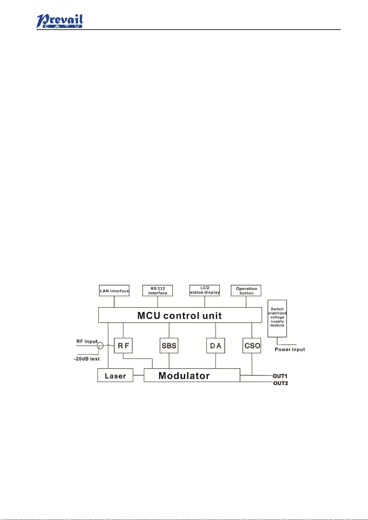
1.4 Block Diagram
1.5 Product Applications
• High-performance long-distance transmission
• High-power distribution network
• Redundancy loop architecture
• FTTx network
• RFOG application
• DWDM network

Manual of Prevail
Rev1.1 190510 www.prevail-catv.com
No. 27-1, Youyi Road, Guali Town, Xiaoshan District, Hangzhou City, Zhejiang Province.
- 3
-
2. Technique Parameters
2.1 Optical Parameters
Item
Unit
Value
Optical Wavelength
nm
1545~1560 (or specified by the user)
Side-mode Suppression ratio
dB
>30
Relative Intensity Noise
dB/Hz
<-160
Wavelength Adjustment Range
GHz
+/-50GHz
Optical Power
dBm
2*7, 2*8, 2*9, 2*10
SBS Threshold Value
dBm
+13~+19 (Continuously adjustable)
Laser Linewidth
MHz
0.3
2.2 Model Test Indicators
Test Model
C42
D59
D84
Channel Plan
CENELEC42
PAL D59
PAL D84
Channel Number TV/FM/QAM64
42/0/0
59/0/0
84/0/0
Bandwidth Noise
5
5
5
CNR Tx/Rx
55.0
54.0
52.5
CNR Link 1
54.0
53.5
52.0
CNR Link 2
53.0
52.5
50.5
CNR Link 3
50.5
50.5
49.0
CSO Tx/Rx and Link 1
64
64
64
CSO Link 2
63
64
64
CSO Link 3
62
62
62
CTB
62
62
62
2.3 Test Condition
First stage
EDFA
First
paragraph
fiber length
Second
stage EDFA
Second
paragraph
fiber length
RX
SBS
(dBm)
Tx/Rx
No
No
No
no
0dBm
13.5
Link 1
No
35km
no
no
0dBm
13.5
Link 2
16dBm
65km
no
no
0dBm
16
Link 3
13dBm
50km
13dBm
50km
0dBm
13.5

Manual of Prevail
Rev1.1 190510 www.prevail-catv.com
No. 27-1, Youyi Road, Guali Town, Xiaoshan District, Hangzhou City, Zhejiang Province.
- 4
-
2.4 Technical Data Sheet
Item
Unit
Technical Parameters
RF range
MHz
47~1003
RF flatness
dB
±0.75
RF return loss
dB
>16
RF input impedance
Ω
75
RF input connector type
F type
Input level range
dBµV
80±5
AGC control range
dB
+3~-3
MGC adjustable range
dB
0~15
Optical connector
SC/APC, FC/APC
Operating temperature
°C
-5~45
Storage temperature
°C
-30~+70
Power Source Specification
V
90~265VAC
36~72VDC
Consumption
W
≤60
Dimension
mm
483(L) ×455(W) ×44(H)
Total Weight
kg
5.5
3. Panel Interface and Menu System Description
3.1 Front Panel
1
Power indicator
2
AGC indicator
3
RF indicator
4
Laser indicator
5
LCD
6
ESC key
7
UP key
8
DOWN key
9
Enter key
10
RF input port (optional)
11
-20dB RF input test port
3.1.1 Indicator Description
Power indicator
One power supply
LED yellow
Two power supplies
LED green
AGC indicator
AGC mode
LED green
MGC mode
LED off
RF indicator
Normal
LED green
Abnormal
LED flash red
Laser indicator
Bias current, cooling current and output
power are all normal
LED green
At least one of bias current, cooling
current and output power is abnormal
LED flash red
Manual of Prevail
Rev1.1 190510 www.prevail-catv.com
No. 27-1, Youyi Road, Guali Town, Xiaoshan District, Hangzhou City, Zhejiang Province.
- 5
-
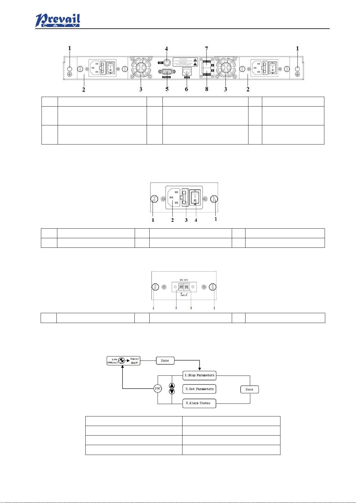
3.2 Rear Panel
1
Ground stud
2
Power module
3
Fan
4
RF input port (or on the front
panel, optional)
5
RS232 interface
6
LAN interface
7
Optical output interface A (or
on the front panel, optional)
8
Optical output interface B (or
on the front panel, optional)
3.3 Power Module
3.3.1 220V Power Module
1
Mounting screws
2
220V power outlet
3
Fuse
4
Power switch
3.3.2 48V Power Module
1
Mounting screws
2
+ Positive terminal block
3
- Negative terminal block
3.4 Menu Operation
3.4.1 Main Menu
Display
Comments
1.Disp Parameters
Menu one: Display parameters
2.Set Parameters
Menu two: Set parameters
3.Alarm Status
Menu three:Alarm status

Manual of Prevail
Rev1.1 190510 www.prevail-catv.com
No. 27-1, Youyi Road, Guali Town, Xiaoshan District, Hangzhou City, Zhejiang Province.
- 6
-
3.4.2 Display Menu
Display
Comments
Display
Comments
Laser Output
Output optical power
+24V Read:
+24V monitor voltage
Laser Bias
Laser current
+12V Read:
+12V monitor voltage
RF CSO
CSO monitor voltage
-12V Read:
-12V monitor voltage
Laser Cooling
Cooling current
LASER:
Laser status
OMI(rms)
Total modulation degree
SBS Module Temp:
SBS module temperature
RF Mode
RF control mode
BOX Temp:
Overall temperature
AGC
Adjusted value with AGC mode
MCU Temp:
MCU temperature
MGC
Adjusted value with MGC mode
S/N:
Serial number
+5V Read:
+5V monitor voltage
Version:
Version number
-5V Read:
-5V monitor voltage
Work Time:
Work time
3.4.3 Set Menu

Manual of Prevail
Rev1.1 190510 www.prevail-catv.com
No. 27-1, Youyi Road, Guali Town, Xiaoshan District, Hangzhou City, Zhejiang Province.
- 7
-
Display
Comments
Remarks
Set RF MODE
Set RF control mode
MGC andAGC two modes selectable
Set AGC
Set MGC
Set RF adjusted value
Adjustable range 0~15dB with MGC mode
Adjustable range -3~+3dB with AGC mode
Set SBS Suppression
Set SBS value
Range 13~19dBm, 0.5dB stepping
Set ITU
Set optical wavelength
Range ±50GHz
Set Channel Distance
Set channel distance
6MHz, 7MHz, 8MHz
Set LASER
Set laser status
ON/OFF
Set IPAddress
Set IP address
Set Mask
Set subnet mask
Set Gateway
Set gateway
Set Trap1 Address
Set trap1 address
Set Trap2 Address
Set trap2 address
Set Buzzer Alarm
Set buzzer alarm
ON/OFF
Restore Factory Cfg
Restore factory settings
3.4.4 Alarm Menu
The displayed alarm content
Comment
RF IN Status
HIGH(LOW)
The RF input signal is high (low)
Laser Bais
HIGH(LOW)
The laser bias current is high (low)
Laser TEC
HIGH
The laser cooling current is high
OutPutPower Status
HIGH(LOW)
The output optical power is high (low)
-5V Status
HIGH(LOW)
The -5V voltage is high (low)
+5V Status
HIGH(LOW)
The +5V voltage is high (low)
+12V Status
HIGH(LOW)
The +12V voltage is high (low)
-12V Status
HIGH(LOW)
The -12V voltage is high (low)
+24V Status
HIGH(LOW)
The +24V voltage is high (low)
Laser
OFF
The laser is off
CSO Initialization failed
The CSO initialization is failed
Power invalid
LEFT(RIGHT )
The left (right) power is invalid
4. Installing the WT-1550-EM20 Optical Transmitter
4.1 Receiving and Inspecting
As you unpack your unit, inspect the shipping container and equipment for damage. Save the shipping
material for future use. If the container or the equipment is damaged, notify both the freight carrier and us.
4.2 Mounting WT-1550-EM20
4.2.1 Mounting the EM20 in the Rack
Mounting the EM3O in the standard 19 inch equipment rack:
1. Place the equipment in the rack.
2. Use four screws fixed the mounting lug on the WT-1550-EM20 front panel to the rack.
3. Reliably ground the equipment. The ground terminal is on the rear panel.
4. Visually inspect each key (button) on the front panel to ensure that it is not trapped under the edge of its
hole. If a key is trapped, tap the key to enable it to move freely.

Manual of Prevail
Rev1.1 190510 www.prevail-catv.com
No. 27-1, Youyi Road, Guali Town, Xiaoshan District, Hangzhou City, Zhejiang Province.
- 8
-
4.2.2 Connecting the RF Cables
Verify the RF input F connector type according to the ordering information, then screw on the matched RF
cable.
4.2.3 Connecting the Optical Fiber Cables
1. Verify the matched WT-1550-EM20 fiber cable connector type according to the ordering information.
2. Verify that the fiber cable connector has been cleaned properly. If the fiber cable connector needs to be
cleaned, follow the cleaning procedure outlined in “Cleaning Patch Cord or Pigtail Fiber Optical
Connectors”.
3. Verify that the WT-1550-EM20 optical connector has not been exposed to any contamination.
NOTE: Any contamination of optical connector can significantly degrade optical link performance. This
degradation will most likely manifest itself as poor signal-to-noise (SNR) performance.
4. Note to butt the nick of the connectors and align them accordingly.
4.2.4 Connecting the Ethernet Cable
You can connect the WT-1550-EM20 to your TCP/IP network in order to monitor and control the transmitter
remotely. After you complete the installation procedures described in this chapter, you can use a network
management system (NMS) to monitor and control the WT-1550-EM20.
To connect the WT-1550-EM20, you must use a shielded and grounded Category 5 Ethernet cable.
To connect the Ethernet cable:
1. Connect an Ethernet cable to the transmitter’s RJ-45 Ethernet port and to your TCP/IP network. The
Ethernet port is on the built-in transponder of the transmitter.
2. Verify that the green Link LED is illuminated, indicating that there is a connection. The Link LED is above
the Ethernet port on the rear panel.
4.2.5 Connecting Power
The WT-1550-EM20 is available in an AC power model or DC power model. After mounting the
WT-1550-EM20 in a rack, follow the power connection procedure below for the model that you are
installing.
The AC-powered WT-1550-EM20 has two optional power supplies 110V and 220V:
110V power supply has two 110 VAC (50/60 Hz) input connector that requires input voltage from 90 to 130
VAC, at 50 to 60 Hz single phase. The AC power plug is located on the rear panel.
220V power supply has two 220 VAC (50/60 Hz) input connector that requires input voltage from 150 to
265 VAC, at 50 to 60 Hz single phase. The AC power plug is located on the rear panel.
The DC-powered WT-1550-EM20 has two -48 VDC input connectors that require input voltage from -36 to
-72 VDC. The DC input connectors are located on the rear panel.
Turn on the power source. It takes about 60 seconds for all systems to operate. When connect one power
supply, the power indicator is yellow; when connect two power supplies, the power indicator is green.

Manual of Prevail
Rev1.1 190510 www.prevail-catv.com
No. 27-1, Youyi Road, Guali Town, Xiaoshan District, Hangzhou City, Zhejiang Province.
- 9
-
5. Communication Setup
5.1 RS232 Communication Interface Description
Adopt DB9 standard connector, the pin definitions as follow:
1: No Connect
2: TX
3: RX
4: No Connect
5: GND
6: No Connect
7: No Connect
8: No Connect
9: No Connect
The serial communication uses the standard NRZ form, 1 starts bit, 8 data bits, 1 stop bit and the baud rate
is 38400.
5.2 Set up the Hyper Terminal
If you have not setup the Hyper Terminal in your Windows system, follow the steps:
Click “start menu programaccessorycommunicationHyper Terminal”:
This results in the following screen:
Then you input your connection name, such as “SNMP38400”,and choose the serial port to connect with
your equipment.As follows:
Manual of Prevail
Rev1.1 190510 www.prevail-catv.com
No. 27-1, Youyi Road, Guali Town, Xiaoshan District, Hangzhou City, Zhejiang Province.
-
10
-
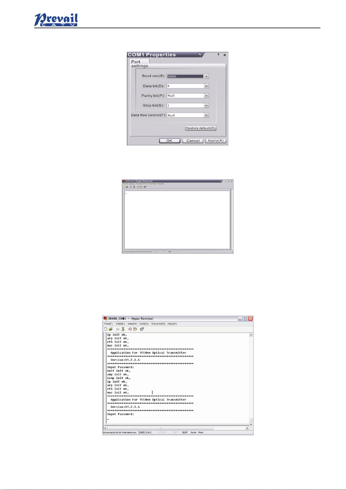
Press the “OK” button shows the configuration page of serial port. As follows:
Change the serial port configuration to 38400-baud rate, 8 data bits, no parity bit, 1 stop bit, no data flow
control, press the “OK” button, you have set up the Windows serial port Hyper Terminal.
You can click “filesave” menu to save this configuration of Hyper Terminal for later using.
5.3 Operating Parameters Configuration
Under the condition of power off, use the serial port lines to connect the RS232 port with the computer port.
Open the Windows Hyper Terminal which you have set up. Then turn on the power, you will see the page
as follows. Enter the password to enter the configuration interface.
Enter the password, display the following screen:
Manual of Prevail
Rev1.1 190510 www.prevail-catv.com
No. 27-1, Youyi Road, Guali Town, Xiaoshan District, Hangzhou City, Zhejiang Province.
-
11
-
You can input your command in this page, and then configure the operating parameter of the application
program.
System supports the following commands:
help
ethcfg
settrap
community
List
Restore
Specific using as follows:
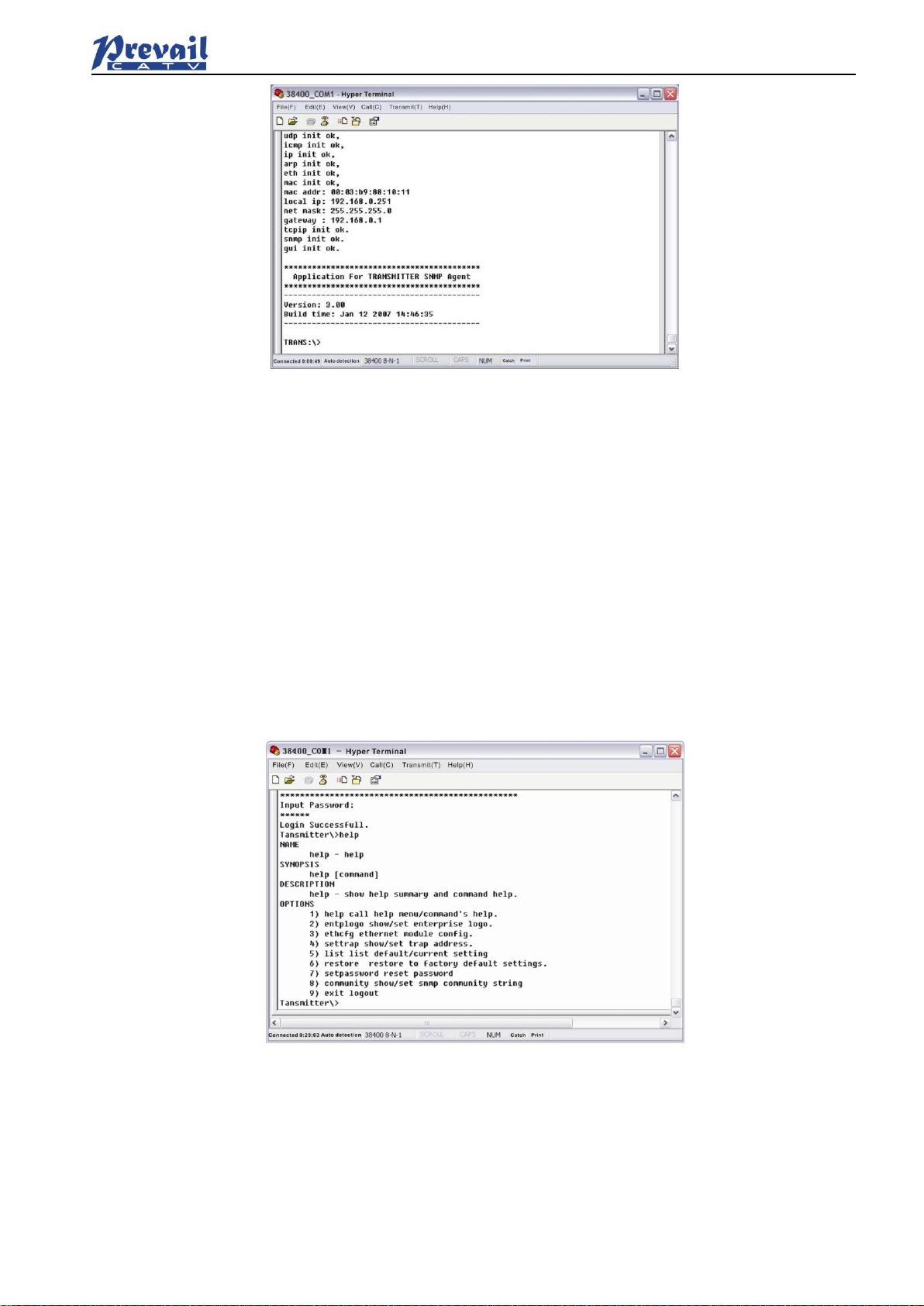
help
This command shows current application program version, program name and the internal commands list
of the system as follows:
You can also use the “help” command to show help information of other commands, such as “help ethcfg”,
ethcfg’s help information appears as follows:
List internal commands of the system;
Configure the Ethernet operating parameters;
Configure the aim host IP address of the SNMP Trap;
Configure the SNMP group name;
List system default parameters or user updated parameters;
Restore the factory default values;

Manual of Prevail
Rev1.1 190510 www.prevail-catv.com
No. 27-1, Youyi Road, Guali Town, Xiaoshan District, Hangzhou City, Zhejiang Province.
-
12
-
ethcfg
This command configures the Ethernet parameters, including IP address, subnet mask and gateway. You
can refer to the help information for its using.
settrap
This command shows or modifies the aim host IP address list of the SNMP Trap,
IP address of 0.0.0.0 and 255.255.255.255 don’t exist. SNMP Trap does not send to these two addresses.
community
This command configures the read-only group name and read-write group name. “Group name” is the
concept of SNMP agreement like the password. Use the command “community ro” to configure the
read-only, and “community rw” for the read-write. For example, input “community rw public”, “public” is the
read-write group name. The group name for read-only and read-write are both “public” as the equipment
default setting from factory.
5.4 Remote Monitoring: SNMP
LAN communication interface
Adopt RJ45 standard connector, the pin definitions as follow:
1: TX+
2: TX-
3: RX+
4: No Connect
5: No Connect
6: RX-
7: No Connect
8: No Connect
A: Green indicator flashing means that the LAN port is sending data.
B: Yellow indicator means that the network connection is normal.
SNMP basic background
Simple Network Management Protocol (SNMP) is an application layer protocol. It makes the management
information between network devices exchange easier. It is part of the TCP / IP protocol group. SNMP
enables the end-users to manage network performance, find and solve network problems, and arrange for

Manual of Prevail
Rev1.1 190510 www.prevail-catv.com
No. 27-1, Youyi Road, Guali Town, Xiaoshan District, Hangzhou City, Zhejiang Province.
-
13
-
future network upgrades.
Management Information Base (MIB) is the organized hierarchical information set. Use SNMP to visit these
MIB. They are composed of manageable information, and identified by the object identifier.
SNMP
Transmitter configuration of network communication
When the transmitter initial work, the IP address and gateway are in the default state, you need to configure
them. The configuration of initial state can be achieved through the RS-232 interface or the front panel keys.
Other configurations see our 5.5 WEB Network Management section.
5.5 WEB Network Management
Open the IE browser, type the IP address and enter the interface as follows:
Type the user name admin and the password 123456 (factory default), enter the following interface:
There are 3 sub-interfaces:
1. About1550 interface: Mainly described the basic information of the equipment.
2. Disp Paraments interface: Mainly described the display menu of the equipment.
3. Set Paraments interface: Change the device parameters in this interface.

Manual of Prevail
Rev1.1 190510 www.prevail-catv.com
No. 27-1, Youyi Road, Guali Town, Xiaoshan District, Hangzhou City, Zhejiang Province.
-
14
-
Click Set Paraments to enter Set Paraments interface as follows:
The Item and Items columns list the parameters that can be changed, the Current column lists the present
parameter values, the New column can select or type the new parameter values, and the Update column
can update the parameters.
The steps to change the parameters: find the item in the Item column, select the new parameter values in
the New column, and click the corresponding Update button to update the parameters.
The change steps in the Items are the same, but finally need to click the Restart Device button to take
effect.
6. Maintenance and Troubleshooting
6.1 Cleaning Fiber Optic Connectors
Dirty optical connectors are the leading source of poor performance in a broadband optical fiber network.
Dirty optical connectors lead to optical signal loss and reflections, which in turn can seriously degrade
signal-to-noise (SNR) performance and, in some cases, distortion performance. We recommend that you
clean all mating fiber connectors before connecting them to an optical transmitter.
In addition, if you suspect that the optical connector of WT-1550-EM20 may have been exposed to
contamination (by a dirty fiber cable connector, for example), you should properly clean the WT-1550-EM20
optical connector before connecting the optical fiber.
6.1.1 Cleaning Patch Cord or Pigtail Fiber Optical Connectors
To clean optical connectors, we recommend using a fiber optic connector cleaning cartridge (such as NTT
Cletop). If a cleaning cartridge is not available, follow these steps.
To clean the optical connector of a patch cord or pigtail:
1. Fold a piece of unused dry lens cleaning paper twice, for a four-ply thickness.
2. Use a drop of high-grade isopropyl alcohol to wet part of the paper.
3. Lay the connector on the lens cleaning paper with the tip touching the paper.
4. In one continuous motion, pull the connector from the wet part of the paper to the dry part.

Manual of Prevail
Rev1.1 190510 www.prevail-catv.com
No. 27-1, Youyi Road, Guali Town, Xiaoshan District, Hangzhou City, Zhejiang Province.
-
15
-
6.2 Troubleshooting
Should a problem occur, see if the symptoms are listed in Table 6-1.
Table 6-1: Troubleshooting Solutions
Indicator
status
Alarm menu content
Fault
phenomenon
Solution
Power
indicator is
yellow
Power Invalid
LEFT (RIGHT)
The left (right)
power is break
down or the power
cord is not
plugged in
Plug in the left (right) power cord. If
that does not correct the problem,
contact Customer Service. Replace
the power supply.
Power
indicator is
flash yellow
-5V Status HIGH (LOW)
+5V Status HIGH (LOW)
+12V Status HIGH (LOW)
-12V Status HIGH (LOW)
+24V Status HIGH (LOW)
Power alarm
menu shows one
of the contents
The laser is off
Contact Customer Service.
RF indicator
is flash red
RF IN Status
LOW (HIGH)
RF input is
low (high)
Verify the optical transmitter is
operating within the proper input level
threshold range,
If that does not solve the problem,
contact Customer Service.
CSO Initialization failed
CSO nonlinearity
indexes are poor
Disconnect the RF connection, wait 10
seconds before reconnecting the RF
signal.
Laser
indicator is
flash red
Laser Bias
HIGH
The laser is off
Contact Customer Service.
Laser TEC
HIGH
The laser is off
Verify that the unit is operating within
the proper temperature range (-5~
+45℃).
Verify that nothing is obstructing
airflow through the openings in the
front and back of the unit.
Recall factory settings by pressing the
key on the front panel (see Section 3).
If that does not correct the problem,
contact Customer Service.
OutPutPower Status
HIGH (LOW)
The laser is off
Reboot the equipment. If that does not
correct the problem, contact Customer
Service.
None
None
The optical output
power is lower
than the nominal
value
Check the fiber connector.
Follow the connector cleaning
procedure (see Section 6.1).
If that does not correct the problem,
contact Customer Service.

Manual of Prevail
Rev1.1 190510 www.prevail-catv.com
No. 27-1, Youyi Road, Guali Town, Xiaoshan District, Hangzhou City, Zhejiang Province.
-
16
-
6.3 After-sales Service Description
If the equipment fault is resulted from the users’ improperly operation or unavoidable environment reasons,
we will responsible maintenance but ask suitable material cost.
When the equipment breaks down, immediately contact local distributor or directly call our technical
support hotline 86-0571-82576002, 18967160936.
The site maintenance of the fault equipment must be operated by professional technicians to avoid worse
damage.
Special notice: If the equipment has been maintained by users, we will not responsible free maintenance.
We will ask suitable maintenance cost and material cost.
6.4 Disclaimer
We reserve the right to change any products described herein at any time, and without prior
notice. We assume no responsibility or liability arising from the use of the products described
herein, except as expressly agreed to in writing by us. The use and purchase of this product
does not convey a license under any patent rights, copyrights, trademark rights, or any
intellectual property rights of us. Nothing hereunder constitutes a representation or warranty
that using any products in the manner described herein will not infringe any patents of third
parties.
Table of contents
Other Prevail-Catv Transmitter manuals


