Prevail-Catv WT-1550-EML User manual

Rev1.0 191107 1
WT1550-EML 光发射机
1. Product Overview
When the 1550nm is used as the downlink transmission wavelength, the expensive price of the 1550nm external modulated
optical transmitter using the Mach-Zehnder Modulator and the severe dispersion effect of the conventional 1550nm directly
modulated optical transmitter are the difficulties in network upgrade. So we have developed a 1550nm optical transmitter
adopting the latest electroabsorption modulated laser (EML). It combines the advantages of the high performance, high SBS of
external modulated transmitter and high integration ,low cost of directly modulated transmitter. SBS can be up to 20dB in distance
transmission in 35KM, MER>40. Supports up to 1.2GHZ frequency band, two-way RF input, high isolation, can support QAM,
IPQAM broadcast, insert functions. Can be built-in CWDM, multi-wavelength networking.
2 Features
● 1.2GHZ frequency band. 35KM,MER>40dB。
● SBS can be up to 20dB, 0.5dB stepping.
● AGC、MGC gain control modes are optional.
● Two-way input, isolation up to 50dB, can achieve high-quality RF insert function.
● Dual power supply hot backup, multiple power supply modes are optional.
● Laser output power, bias current, and cooling current are detected in real time.
● Dual power supply hot backup,AC220V,DC48V are optional。
● Can be equipped with CWDM(optional) to achieve optical insertion.
● Support SNMP network management software and WEB network management.
3 Block diagram
Note: The optical attenuator and wavelength division multiplexer in the dotted box are optional.
WT-1550-EML Optical Transmitter
Unicor s.a.
Unicor s.a.
Cordoba – Argentina - www.unicorsa.com.ar
Created in Master PDF Editor

Rev1.0 191107 2
OUT:10
Unit:dBm
RF:30.5
Unit:dBuV
4 Technical Parameter
Items Unit Technical Parameter
Optical part
Optical wavelength nm 1550 (ITU wavelength is optional)
Laser type Electroabsorption modulated laser(EML)
Optical connector type FC/APC or SC/APC
Output optical power mW 10 Exclude optical attenuator and CWDM insertion loss
External optical input power
(main channel) dBm -5~10
RF part
Frequency Range MHz 47~870/1003/1218
RF input level dBuV 77± 5
Flatness in band dB ± 0.75
Input return loss dB ≥ 16
RF AGC control range dB ±5
RF MGC adjustable range dB 0~20
SBS dB 13~20,0.5dB stepping
RF input isolation dB ≥ 50 Isolation between two RF inputs
RF input test port dB -20±1
Laser drive RF level test port dB -20±1
Electronically controlled optical
attenuator tolerance
dB
≤1:attenuator 0-15dB
≤3:attenuator 16-20dB
CNR dB ≥ 52 0Km,-1dBm receiver,59CH analog +40CH digital,77dBuV
C/CSO dB ≥ 58 SBS:20dBm,25Km,-1dBm receiver
59CH analog +40CH digital,77dBuV
C/CTB dB ≥ 58
MER dB ≥ 40 SBS:20dBm,25Km,-1dBm receiver
96CH 256QAM digital,77dBuV。
BER ≤10e-8
Others
Maximum power consumption W ≤15
Operating temperature ℃-5 ~+ 55
Storage temperature ℃-30 ~+ 70
Weight Kg 5.5
5 Display menu operation instructions
▲▼key: The cursor can be moved left or right or up and down, and the selected module or menu is highlighted.
Enter key: Press Enter to enter the next submenu or set the submenu. After the setting is completed, press Enter to confirm.
ESC key: Exit or return to the previous menu.
Visible display content after boot: Press Enter to enter the Level 1 submenu:
Laser drive level Output optical power
1.Disp Parameters
2.Set Parameters
3.Alarm Status
Parameter display menu
Parameter setting menu
Alarm status
Cordoba – Argentina - www.unicorsa.com.ar
Created in Master PDF Editor

Rev1.0 191107 3
Optical power unit:dBm、mW are optional
Buzzer alarm:ON、OFF are optional
RF control mode:AGC、MGC are optional
MGC attenuation:0-20 are optional
AGC Offset:±3dB is optional
Set the optical power attenuation mode:AUTO、Manu are optional this menu is not
visible without the
WDM model.
Set the optical power attenuation:0~15dB are optional.
Set the difference between the main optical power and the inserted
o
p
tical
p
ower
Set SBS,13~20dB,0.5dB stepping
Number of channels:0-100 are optional
Set the local IP address
Set the subnet mask
Set gateway
Restore factory configuration
Laser output optical power
optical power after the attenuator, this menu is not visible without the WDM model.
External optical input power, this menu is not visible without the WDM model.
Laser bias current
Internal temperature of the laser
Laser cooling current
Number of transmission channels of the system
Laser drive level
RF control mode
AGC Offset (This menu is only available in AGC mode.)
MGC Attenuation (This menu is only available in MGC mode.)
Wavelength
+5V Monitoring voltage
-5V Monitoring voltage
+24V Monitoring voltage
Serial number
Current temperature inside the machine
IP address of this machine
Subnet mask of this machine
Gateway of this machine
MAC address of this machine
机内软件系统的版本号
SetLaserOutputUnit dBm
Set BuzzerAlarm ON
SetRF ControlMode AGC
Set MGC ATT XX dB
Set AGC Ref XX dB
Set OPT ATT Mode AUTO
Set OPT ATT XX dB
Set OPT Delta XX dB
Set SBS
SetChannel Number XX
Set IP Addr
Set Subnet Mask
Set GateWay
Restore Factory Config
Laser Output xx dBm
Voa Input xx dBm
Master Input xx dBm
Laser Bias xx mA
Laser Temp xx ℃
Tec current xx A
RF Chan No xx
Laser RF xx dBuV
RF Ctrl Mode AGC
AGC Ref x dB
MGC ATT x dB
Wave Length 1550
+5V Read x v
-5V Read x v
+24V Read x v
S/N
BOX Temp xx ℃
IP Address
Mask
GTW
Mac
SoftWare Ver
Drive level alarm:The default normal range is 80 to 110dBuV, which can be set through the network management.
Laser temperature alarm:The default normal range is 25±10°C, which can be set through the network management.
Laser bias current alarm:The default normal range is 20 to 90 mA, which can be set through the network management.
Laser cooling current: The default normal range is -1.5~1.5A, which can be set through the network management.
Output optical power alarm: The default normal range is 2 to 25 mW, which can be set through the network management.
+5V alarm:The default normal range is 5±1V, which can be set through the network management.
-5V alarm:The default normal range is -5±1V, which can be set through the network management.
+24V alarm:The default normal range is 24±2V, which can be set through the network management.
Disp Parameters Level 2 submenu:
Set Parameters Level 2 submenu:
Alarm Status Level 2 submenu:
Laser RF
Laser Temp
Laser Bias
Laser TEC
Laser Output
+5V Alarm
-5V Alarm
+24V Alarm
Cordoba – Argentina - www.unicorsa.com.ar
Created in Master PDF Editor

Rev1.0 191107 4
6 Structure Description
Front panel
1Power Indicator
2Running indicator: 1HZ frequency flashing green when the device is working normally
3Laser working status indicator:Green light is always on: the laser is working normally.
Red light is always on: the laser is not turned on
Red light is flashing: The device has a parameter alarm. You can view the alarm content in the
Alarm Status Level 2 submenu.
4Laser drive level indicator:Green light is always on: drive level is normal.
Red light is flashing: drive level alarm. You can view the alarm content in the Alarm Status Level 2
submenu.
5Laser switch key:ON:Laser is on
OFF:Laser is off. Keep the laser off before the device is powered on, and turn on the laser after the power-on
self-test is completed.
6Laser drive level detection port:-20dB
Rear panel
1Fan 5RF input 1 test port -20dB 9RS232 interface
2Ground stud 6RF input 2 test port -20dB 10 LAN interface
3RF input 1 7Optical signal output 11 Power supply1, hot swappable
4RF input 2 8Optical signal input, there is no interface without
the WDM model.
12 Power supply 2 , hot swappable
Cordoba – Argentina - www.unicorsa.com.ar
Created in Master PDF Editor

Rev1.0 191107 5
7. WEB Network Management
Opening the IE browser and entering the equipment IP address, then enter the user name admin and password 123456 (factory
default), to show the following interface:
There are 3 sub-interfaces:
1. Display Parameter interface: Describes the equipment display menu.
2. Set Parameter interface: Change the equipment parameters in this interface.
3. Modify password interface: Change the login password in this interface.
Click Set Parameter to open the following interface:
The Item shows the changeable parameters, Current—the current parameters; New—select or enter the new parameters;
Update—update the parameters.
The update steps: Find the item which needs to be changed, select a new value, and click the Update button.
Cordoba – Argentina - www.unicorsa.com.ar
Created in Master PDF Editor
Rev1.0 191107 6
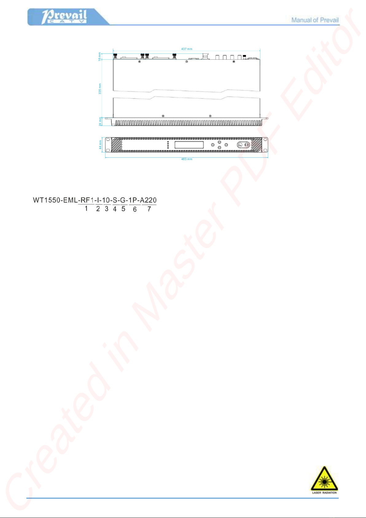
8 Dimension
9Naming Specification
1. RF1: One way RF input. RF2: two way RF inputs.
2. I:Standard model, no WDM.
II:Standard model + built-in WDM wavelength division multiplexer + built-in VOA electrical variable optical attenuator.
3. Output power mW。
4. S:SC/APC. F:FC/APC。
5. G male,Y female。
6. 1P single power supply,2P dual power suppliers.
7. A220:AC220V,DC48:DC48V
8. The output is optional ITU standard wavelength, please specify the specific wavelength requirements in the order.
9. Please specify the WDM specification parameters in the order when selecting WDM.
10. Standard front panel is black engineering plastic material.
11. Standard optical interface and RF interface location are on the rear panel.
12. Standard Ethernet transponder.
10 Attention
●Before unpacking, please confirm that the outer packaging is intact. If you think that the equipment has been damaged due to
transportation, etc., do not power on to avoid more serious damage to the equipment or accidental injury to the operator.
●Before powering on the equipment, make sure that the grounding end of the chassis and power socket is reliably grounded.
The grounding resistance should be <4Ω, which can effectively protect against surge and static electricity.
●The optical transmitter is a professional and technical equipment. The installation and debugging must be carried out by
professional technicians. Please read this manual carefully before operation to avoid damage to the equipment due to
misoperation or accidental injury to the operator.
●When installing and debugging the optical device, there may be an invisible laser beam in the fiber connector. The fiber optic
connector should be avoided to be aimed at the human body, even not be directly viewed by the naked eye to avoid permanent
damage to body and eye!
●When the fiber connector is not in use, it should be put on the dust jacket to avoid dust pollution and keep the
fiber end face clean.
Cordoba – Argentina - www.unicorsa.com.ar
Created in Master PDF Editor
Table of contents
Other Prevail-Catv Transmitter manuals


