TDT200
2676E JUL 18
V+
02
3
4
Temp 0 - 10V DC
TDT200
1
2
3
V+
Temp 4 - 20mA
TDT200-420
1
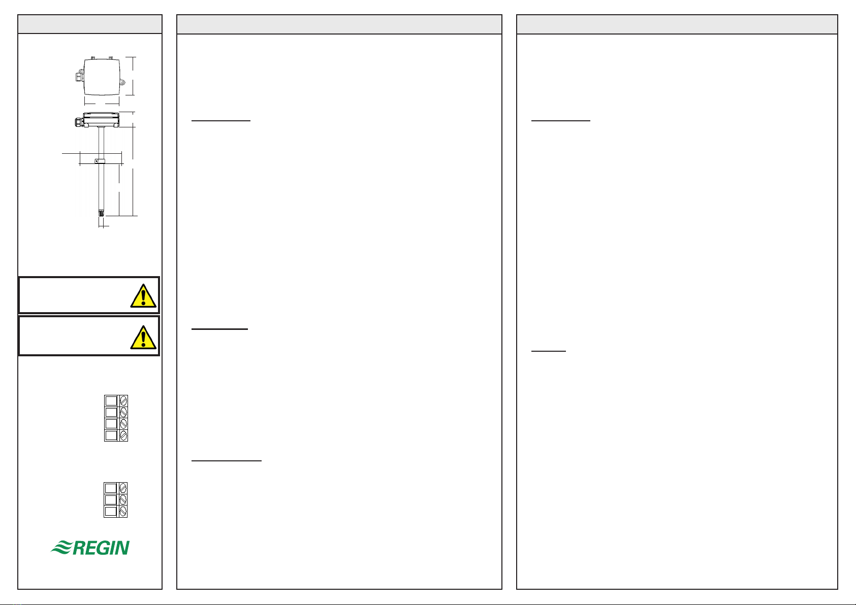
85
90
35
220
20-200
Ø12
100
Box 116
428 22 KÅLLERED SWEDEN
Tel +46 (0)31 720 02 00 Fax +46 (0)31 720 02 50
INSTRUKTION INSTRUCTIONS
Temperaturgivare för kanalmontage
TDT200 är en kanalmonterad temperaturgivare för mätning av tempera-
tur i klimat- och luftbehandlingsanläggningar.
Finns med 0 - 10V DC eller 4 - 20mA utsignaler.
Installation
Givaren monteras i kanal antingen med hjälp av skruvckorna i appa-
rathuset eller med hjälp av den bifogade fästänsen. Med fästänsen
nns två alternativa fästmetoder:
1. Lossa de tre fästskruvarna som håller fast den kloförsedda insatsen i
änsen. Tag ut insatsen. Borra ett Ø22mm hål i kanalväggen och pressa
in insatsen så att klorna snäpper fast kring hålkanten. Skruva åter fast
resten av fästänsen. Stick in och xera givaren vid önskat insticksdjup.
OBS: Denna metod kan bara användas vid plåttjocklek <4mm.
2. Lossa de tre fästskruvarna som håller fast den kloförsedda insatsen i
änsen. Tag ut insatsen och klipp bort klorna. Skruva åter fast den i än-
sen. Borra ett 20 - 26mm hål i kanalväggen och fäst änsen med hjälp
av de två skruvhålen på ömse sidor om mitthålet. Fästhålen har c:c-mått
40mm. Stick in och xera givaren vid önskat insticksdjup.
Vid applikationer i starkt förorenade miljöer bör känselkroppens mem-
branlter bytas mot ett sintrat mässingslter.
Inkoppling
Koppla in matningsspänning och signalkablage i enlighet med den kopp-
lingsbild som gäller för den installerade enheten.
Matningsspänning:
TDT200 24V AC +/-20% eller 20...35V DC.
TDT200-420 20...35V DC.
Utsignal:
0 - 10V DC (4...20mA) vilket motsvarar 0...50°C.
Belastningsimpedans:
TDT200 Minimum 10kΩ.
TDT200-420 Maximum 500Ω.
Teknisk hjälp
Hjälp och råd på telefon: 031 - 720 02 30.
Duct mounted temperature sensor
TDT200 is a duct mounted temperature sensor for measuring tempera-
ture in air handling systems.
Available with 0 - 10V DC or 4 - 20mA output signals.
Installation
Mount the sensor in the duct using either the screw pockets in the enclo-
sure or the mounting ange provided. When using the ange there are
two alternative methods:
1. Loosen the three screws holding the claw insert to the ange. Re-
move the insert. Drill a Ø22mm hole in the duct wall and press the insert
into the hole so that the claws snap onto the hole circumference. Refas-
ten the rest of the ange onto the insert. Mount the sensor stem through
the hole in the ange and x it at desired depth.
N.B. This method is only suitable with duct walling thinner than 4mm.
2. Loosen the three screws holding the claw insert to the ange.
Remove the insert and cut off the claws. Remount the insert in the
ange. Drill a 20 - 26mm hole in the duct wall and mount the ange over
the hole using the two screw holes on the ange. These holes have a c:c
distance of 40mm. Mount the sensor stem through the hole in the ange
and x it at desired depth.
When mounted in contaminated environments the sensor’s membrane
lter should be exchanged for a sintered brass lter.
Wiring
Connect supply voltage and output signals according to the diagram for
the unit being installed.
Supply voltage:
TDT200 24V AC +/-20% or 20...35V DC.
TDT200-420 20...35V DC.
Output signal:
0 - 10V DC (4...20mA) corresponding to 0...50°C.
External load impedance:
TDT200 Minimum 10kΩ.
TDT200-420 Maximum 500Ω.
VIKTIGT: Läs denna
instruktion innan produkten
monteras och ansluts.
IMPORTANT: Read these
instructions before installing
and wiring the product.
CE
This product carries the CE mark. More information is available
at www.regincontrols.com
CE
Denna produkt är CE-märkt. Mer information nns
på www.regincontrols.com


