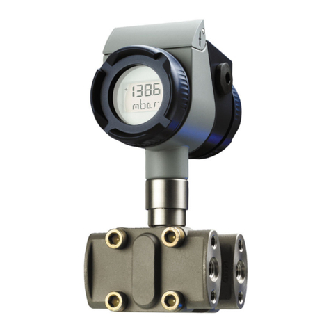
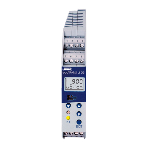
JUMO 404304 Series User manual

40430400T90Z000K000
EN/00392602
Pressure and differential pressure transmitters
Operating Instructions


Content
1 Typographical conventions ............................................................................................................. 5
1.1 Warning signs ...................................................................................................................................... 5
1.2 Note signs ............................................................................................................................................ 5
2 General .............................................................................................................................................. 6
2.1 Preface ................................................................................................................................................ 6
2.2 Application ........................................................................................................................................... 7
3 Identifying the device vision ............................................................................................................ 8
3.1 Order details ........................................................................................................................................ 8
4 Mounting .......................................................................................................................................... 10
5 Installation ....................................................................................................................................... 11
5.1 Electrical connection .......................................................................................................................... 11
6 Commissioning ............................................................................................................................... 13
7 Calibration ....................................................................................................................................... 14
8 Setting the limit contacts ............................................................................................................... 15

5
1 Typographical conventions
1.1 Warning signs
1.2 Note signs
Danger
This sign is used when there may be danger to personnel if the instructions
are disregarded or not followed accurately.
Caution
This sign is used when there may be damage to equipment or data if the
instructions are disregarded or not followed accurately.
Note
This sign is used when your special attention is drawn to a remark.
➩Reference
This sign refers to further information in other chapters or sections.
abc1Footnote
Footnotes are notes which refer to certain points in the text.
Footnotes consist of two parts:
Marking in the text and the footnote text.
The marking in the text is arranged as continuous superscript numbers.
✱Action
This sign indicates that an action to be performed is described.
The individual steps are marked by this asterisk.
Example:
✱Remove crosspoint screw
✱Set potentiometer

6
2 General
2.1 Preface
Please read these Operating Instructions before commissioning the instrument.
Keep the instructions in a place which is accessible to all users at all times.
Please assist us to improve these operating instructions, where necessary.
Your suggestions will be welcome.
All the necessary settings are described in this manual. However, if
any difficulties should still arise during commissioning, you are
asked not to carry out any unauthorized manipulations on the unit.
You could endanger your rights under the instrument warranty!
Please contact the nearest subsidiary or the head office in such a
case.
When returning modules, assemblies or components, the
regulations to EN 100 015 “Protection of electrostatically sensitive
components” must be observed. Use only the appropriate ESD
packaging for transport.
Please note that we cannot accept any liability for damage caused
by ESD (electrostatic discharge).

7
2 General
2.2 Application
General note Pressure and differential pressure transmitters Type 404304 are used for mea-
suring very low pressures.
Corresponding to the measuring range, the CuBe diaphragm inside
the instrument is very sensitive.
Do not blow into the pressure connections, as this may
damage or destroy the instrument.
The instrument is suitable for non-corrosive gases only.
The instrument has no Ex approval.

8
3 Identifying the device vision
3.1 Order details
(1) Basic type
404304 Pressure transmitter with inductive measuring system
(2) Basic type extensions
000 none
011 with one limit contacta
012 with two limit contactsa
013 LCD readout, 31/2-digit
014 with one limit contact and LCD readout, 31/2-digita
015 with two limit contacts and LCD readout, 31/2-digita
(3) Nominal input range
396 0 to 10 Paa/b
397 0 to 20 Paa/b
398 0 to 30 Paa/b
399 0 to 40 Paa/b
400 0 to 0.5 mbar
401 0 to 0.6 mbar
402 0 to 1 mbar
403 0 to 1.6 mbar
404 0 to 2.5 mbar
405 0 to 4 mbar
406 0 to 5 mbar
407 0 to 6 mbar
408 0 to 10 mbar
409 0 to 16 mbar
410 0 to 25 mbar
411 0 to 40 mbar
412 0 to 50 mbar
413 0 to 60 mbar
414 0 to 100 mbar
415 0 to 160 mbar
420 950 to 1050 mbar, absolutec
421 900 to 1100 mbar, absolutec
422 800 to 1200 mbar, absolutec
423 800 to 1000 mbar, absolutec
451 0 to 0.25 bar
452 0 to 0.4 bar
453 0 to 0.6 bar
454 0 to 1.0 bar
488 0 to 1.0 bar, absolutec
999 Special measuring range

9
3 Identifying the device vision
(4) Output
402 0 to 20 mA
403 0 to 20 mA, square root
405 4 to 20 mA, 2-wire
406 4 to 20 mA
407 4 to 20 mA, square root
415 0 to 10 V
416 0 to 10 V, square root
451 0 to 20 mA, extended response time
452 0 to 20 mA, square root, extended response time
453 0 to 20 mA, 2-wire, extended response time
454 4 to 20 mA, extended response time
455 4 to 20 mA, square root extended response time
456 0 to 10 V, extended response time
457 0 to 10 V, square root, extended response time
(5) Voltage supply
02 230 V -10 % to +6 % AC, 50 to 60 Hz
05 115 V -10 % to +6 % AC, 50 to 60 Hz
08 24 V -10 % to +6 % AC, 50 to 60 Hz
27 DC 11.5 to 30 V (with 4 to 20 mA 2-wire output)
28 DC 19 to 31 V
(6) Process connection
296 screwed pipe connection 8 mm
298 6.6 × 11 mm dia. (for flexible hoses 6 mm dia.)
anot with 2-wire output (405 or 453), not with DC 11.5 to 30 V (voltage supply 27)
bwith housing 122 mm × 120 mm × 75 mm and automatic zeroing, not with 2-wire output (405 or
453)
cfor barometric pressure measurement (if applicable, state site altitude a.m.s.l)
(1) (2) (3) (4) (5) (6)
Order code /
Order example 404304 / 000 - 414 - 406 - 02 - 298

10
4 Mounting
Fixing ✱Use the lugs to fix the instrument.
The instrument should preferably be fixed vertically (pressure
connections below), since it has been factory-calibrated in this posi-
tion.
This ensures that no condensate from the pressure lines will enter
the measuring system.
Do not install the instrument close to sources of interference (trans-
formers, transmitters, motors) or heat sources.
Shock or vibration will lead to measurement errors.

11
5 Installation
5.1 Electrical connection
Opening the
instrument
✱Unscrew the four slotted screws
✱Remove cover
Connection
When connecting the instrument, please observe the VDE regulati-
ons concerning work with mains supply voltage, as well as the
regulations of the trade insurance associations regarding work on
and with electrical equipment and installations.
Never connect the supply voltage to the output terminals!
For the required supply voltage, see nameplate.
Instruments with DC supply have a reverse polarity protection.
Connection Terminals
Terminal
block
Voltage supply
DC 11.5 to 30 V, 19 to 31V
L -
L +
1
2
Voltage supply
AC 230 V, 115 V, 24 V
N
L 1
1
2
Output
0 to 10 V, 0/4 to 20 mA, 3-wire
-
+
3
4

12
5 Installation
Connection
2-wire
Connection Terminals
Terminal
block
Output
4 to 20 mA, 2-wire
DC 12 to 32 V
proportional current in supply line
-
+
1
2
12
Multimeter
Supply
+-
TP4 OFFSET
TP3 - SPAN
TP2 + SPAN
TP1 ZERO TP5 LCD
Time control
+
-
+
-

13
6 Commissioning
After
connecting the
supply voltage
The output signal can be measured after the supply voltage has been con-
nected.
For gauge pressure measurement, connect the pressure to be
measured to the “+” input. The other pressure connection remains
open.
The warm-up time for the instrument is 1hour.
After this time (at a constant ambient temperature), the output sig-
nal with differential pressure measurement must have stabilized at
zero.
With short ranges, the mounting position can cause a zero shift.
This shift can be compensated after the warm-up time by using the
potentiometer TP1 (zero).

14
7 Calibration
Required aids • pressure generator
• reference pressure measuring device
• supply for pressure /differential pressure transmitter
• voltmeter/ammeter (multimeter)
Setup
Setup
2-wire
Calibrating ✱Open instrument, see "Opening the instrument", page 11.
✱Connect voltage supply, see "Connection", page 11ff.
✱Connect multimeter, see "Connection", page 11ff.
✱Wait for instrument to warm up (approx. 1 hour).
✱Set zero:
With open pressure connections, set display value of multimeter to 0 V
(with current output to 0(4) mA) by using the potentiometer TP1.
✱Set nominal pressure:
Apply nominal pressure to instrument at the “+” pressure connection.
Using the potentiometer TP2, set display value of multimeter to 10 V
(to 20 mA with current output).
Only adjust the instrument potentiometers listed in the instructions
below! The other potentiometers are factory-set and must not be
adjusted!
12
Multimeter
Supply
Pressure
generator
Reference
pressure
+-
TP4 OFFSET
TP3 - SPAN
TP2 + SPAN
TP1 ZERO TP5 LCD
Time control
+
-
+
-

15
8 Setting the limit contacts
Required aids • pressure generator
• supply for pressure/differential pressure transmitter
• reference pressure measuring device or voltmeter/ammeter (multimeter)
Controls
Description
Rating of limit contact: 6 A max. at 230 VAC
5678910
TP6
TP7 TP8
J4
GK2
ST4
GK1
J2J1
ST5
J3
TP3 TP4
TP5
TP2
TP1
GK1 Terminal 5, 6, 7
GK2 Terminal 8, 9, 10
TP1 Potentiometer for limit of limit contact 1 (GK1)
Setting range: 0 to 100 % of full scale
TP2 Potentiometer for hysteresis of GK1
Setting range: 1 to 99 % of full scale
TP3 Potentiometer for switch-on delay of GK1
Setting range: 0 to 10 sec
TP4 Potentiometer for switch-off delay of GK1
Setting range: 0 to 10 sec
TP5 Potentiometer for limit of limit contact 2 (GK2)
Setting range: 0 to 100 % of full scale
TP6 Potentiometer for hysteresis of GK2
Setting range: 1 to 99 % of full scale

16
8 Setting the limit contacts
TP7 Potentiometer for switch-off delay of GK2
Setting range: 0 to 10 sec
TP8 Potentiometer for switch-off delay of GK2
Setting range: 0 to 10 sec
J1 Jumper for switching point of GK1 in the positive/negative
pressure ranges (for ± ranges)
Bridge 1-2 => GK1 switches in the positive
pressure range
Bridge 2-3 => GK1 switches in the negative
pressure range
J2 Jumper for switching point of GK2 in the positive/negative
pressure ranges (for ± ranges)
Bridge 1-2 => GK2 switches in the positive
pressure range
Bridge 2-3 => GK2 switches in the negative
pressure range
J3 Jumper for relay function of GK1
Bridge 1-2 => GK1 = min. limit contact
Bridge 2-3 => GK1 = max. limit contact
J4 Jumper for relay function of GK2
Bridge 1-2 => GK2 = min. limit contact
Bridge 2-3 => GK2 = max. limit contact
1
2
3
1
2
3
1
2
3
1
2
3
1
2
3
1
2
3
1
2
3
1
2
3

17
8 Setting the limit contacts
Preparation ✱Open the instrument, see "Opening the instrument", page 11.
✱Connect voltage supply, see "Connection", page 11ff.
✱Connect multimeter, see "Connection", page 11ff.
✱Wait for instrument to warm up (approx. 1hour).
Defining the
switching range
(only for "+/-"
ranges)
✱Use jumper J1 (for GK1) or J2 (for GK2) to determine whether the limit
contact switches in the positive or the negative pressure range. For jumper
functions, see table above.
Setting the
relay function
✱Use jumper J3 (for GK1) or J4 (for GK2) to determine whether the relay
switches as max. limit contact (relay switches when the actual value is
larger than the setpoint) or as min. limit contact (relay switches when the
actual value is smaller than the setpoint). For jumper functions, see table
above.
Setting the limit
contact with a
reference
pressure mea-
suring device
✱Set switch-on and switch-off delay to 0 (turn fully to the left) by using the
potentiometer TP3/7 or TP4/8.
✱Apply the pressure at which the limit contact has to switch to the pressure
transmitter.
✱Keep on adjusting the potentiometer TP1 (for GK1) or TP5 (for GK2), until
LED GK1 or GK2 lights up.
✱Apply the pressure at which the limit contact has to switch back to the pres-
sure transmitter.
✱Keep on adjusting the potentiometer TP2 (for GK1) or TP6 (for GK2), until
the LED GK1 or GK2 goes dark.
ST4 Multimeter connection for testing limit contact 2 (GK2)
1-3 => switching point of limit contact
Example 1: measuring range 0 to 3 hPa,
switching point at 1.5 hPA (50%) => 0.5 V
Example 2: measuring range -2 to +8 hPa,
switching point at +3.5 hPA (55%) => 0.55 V
1-2 => hysteresis of limit contact
Example: limit = 0.5 V,
hysteresis = 10% => 0.45 V
ST5 Multimeter connection for testing GK2
GK1 LED GK1
GK2 LED GK2
1
2
3
1
2
3
1
2
3

18
8 Setting the limit contacts
Setting the
limit contact
by using a
multimeter
✱Connect multimeter to connector ST4 (for GK1) or ST5 (for GK2), see table
above.
✱Set switch-on and switch-off delay to 0 (turn fully to the left) by using the
potentiometer TP3 (for GK1) or TP7 (for GK2) (switch-on delay) and TP4 or
TP8 (switch-off delay).
✱Set the voltage that corresponds to the switching point by means of the
potentiometer TP1 (for GK1) or TP5 (for GK2).
Example: range 0 to +3 hPa; desired switching point 1.8 hPa => 60 % of
range; the corresponding voltage at the connector ST4 or ST5 is 0.6 V
Setting the swit-
ching
hysteresis
by using a
multimeter
✱Connect multimeter to connector ST4 (for GK1) or ST5 (for GK2), see table
above.
✱Set switch-on delay and switch-off delay to 0 (turn fully to the left) by using
the potentiometer TP3 (for GK1) or TP7 (for GK2) (switch-on delay) and TP4
or TP8 (switch-off delay).
✱Using the potentiometer TP2 (for GK1) or TP6 (for GK2), set the voltage that
corresponds to the hysteresis.
Example: switching point at 0.5 V; desired hysteresis 10 %; corresponding
voltage at the connector ST4 or ST5 is 0.45 V
Setting the
switch-on or
switch-off delay
✱Set the switch-on delay using the potentiometer TP3 for GK1 or TP6 for
GK2 within the range 0 to 10 sec.
✱Set the switch-off delay with the potentiometer TP4 for GK1 or TP8 for GK2
within the range 0 to 10 sec.
The range 0—100% always corresponds to 0 to 1 V, e.g.:
pressure range 0 to +3 hPa corresponds to 0 to 1 V
pressure range -3 to +3 hPa corresponds to -0.5 to +0.5 V
pressure range -2 to +8 hPa corresponds to -0.2 to +0.8 V

JUMO GmbH & Co. KG JUMO Instrument Co. Ltd. JUMO Process Control, Inc.
Street address:
Moritz-Juchheim-Straße 1
36039 Fulda, Germany
Delivery address:
Mackenrodtstraße 14
36039 Fulda, Germany
Postal address:
36035 Fulda, Germany
Phone: +49 661 6003-0
Fax: +49 661 6003-607
Email: [email protected]
Internet: www.jumo.net
JUMO House
Temple Bank, Riverway
Harlow, Essex, CM20 2DY, UK
Phone: +44 1279 63 55 33
Fax: +44 1279 62 50 29
Email: [email protected]
Internet: www.jumo.co.uk
6733 Myers Road
East Syracuse, NY 13057, USA
Phone: +1 315 437 5866
Fax: +1 315 437 5860
Email: [email protected]
Internet: www.jumousa.com
Other manuals for 404304 Series
1
Table of contents
Other JUMO Transmitter manuals

JUMO
JUMO B 707025.0 User manual

JUMO
JUMO dTRANS T03 J User manual

JUMO
JUMO dTRANS p02 DELTA User manual

JUMO
JUMO CTI-750 User manual

JUMO
JUMO TRANS T06 Junior User manual

JUMO
JUMO 4AP-30 User manual

JUMO
JUMO JUMO dTRANS p20 DELTA User manual

JUMO
JUMO AQUIS 500 Ci User manual

JUMO
JUMO dTRANS T03 Series User manual

JUMO
JUMO HART dTRANS p20 Ex d User manual

JUMO
JUMO CTI-500 User manual

JUMO
JUMO JUMO dTRANS p20 DELTA User manual

JUMO
JUMO dTRANS p02 User manual

JUMO
JUMO 907021/10 User manual

JUMO
JUMO CTI-750 User manual

JUMO
JUMO CTI-750 User manual

JUMO
JUMO dTRANS O2 01 User manual

JUMO
JUMO Wtrans p User manual

JUMO
JUMO dTRANS AS 02 User manual

JUMO
JUMO dTRANS T09 AS User manual