Price Antec controls CAVA User manual

CAVA
Touchscreen Fume Hood Controller
MANUAL v100

CAVA - MANUAL
i | CAVA – Manual | AntecControls.com
TABLE OF CONTENTS
TABLE OF CONTENTS ......................................................................................................................................................................I
INTRODUCTION ...............................................................................................................................................................................1
General..........................................................................................................................................................................................1
Product Overview .........................................................................................................................................................................1
Features ........................................................................................................................................................................................1
Installation & Service.....................................................................................................................................................................1
Technical Specifications ................................................................................................................................................................1
Sash, Sidewall & Hybrid Configuration..........................................................................................................................................2
MECHANICAL INSTALLATION.........................................................................................................................................................3
Mounting Options .........................................................................................................................................................................3
ELECTRICAL INSTALLATION...........................................................................................................................................................4
Wiring............................................................................................................................................................................................4
Room Information Network (RIN) .................................................................................................................................................5
Controller Area Network (CANbus) ...............................................................................................................................................6
BACnet MS/TP Network ...............................................................................................................................................................7
Network Architecture Summary ...................................................................................................................................................8
FUME HOOD ACCESSORIES ..........................................................................................................................................................9
Fume Hood Valve Module (FVM) - Venturi Valve (VV) Applications ..............................................................................................9
Fume Hood Valve Module (FVM) - Venturi FX Valve (VFX) and Terminal Unit (TU) Applications ................................................11
Sash Position Sensor (SPS).........................................................................................................................................................13
Sidewall Velocity Sensor (SVS)....................................................................................................................................................15
Fume Hood Presence Sensor (FPS)............................................................................................................................................18
INTERFACE.....................................................................................................................................................................................19
Home Screen ..............................................................................................................................................................................19
Configurable Fume Hood Modes ................................................................................................................................................20
Settings .......................................................................................................................................................................................21
MAINTENANCE ..............................................................................................................................................................................22
Troubleshooting ..........................................................................................................................................................................22
Replacement Parts......................................................................................................................................................................23
Technical Support........................................................................................................................................................................23
APPENDIX A ...................................................................................................................................................................................24
Cava™ Jigsaw Cut-Out ...............................................................................................................................................................24
Cava™ Circular Cut-Out...............................................................................................................................................................24
Fume Hood Presence Sensor .....................................................................................................................................................24

CAVA - MANUAL
1 | CAVA – Manual | AntecControls.com
INTRODUCTION
General
In this manual, you will find:
•Cava™ technical specifications
•Cava™ mechanical and electrical installation
•Fume hood accessories
•Cava™ interface navigation and configuration
•Troubleshooting information
Please refer to the project specifications, mechanical and electrical
plans, and the Antec Controls project submittal documents for project-
specific wiring and configuration details.
Product Overview
Cava™ is an exceptionally versatile fume hood controller that precisely
monitors and controls fume hood face velocity. Designed specifically
to meet the needs of all fume hood types, Cava™ provides assurance
that required fume hood face velocity is satisfied and the work
environment is safe, while eliminating unnecessary energy usage.
Cava™ delivers effective control using Venturi Valves, Venturi FX
Valves, or terminal units on fume hoods and biosafety cabinets.
Cava™ is intended for continuous, 24-hour fume hood face velocity
control and monitoring, and will automatically resume upon restart
after losing power.
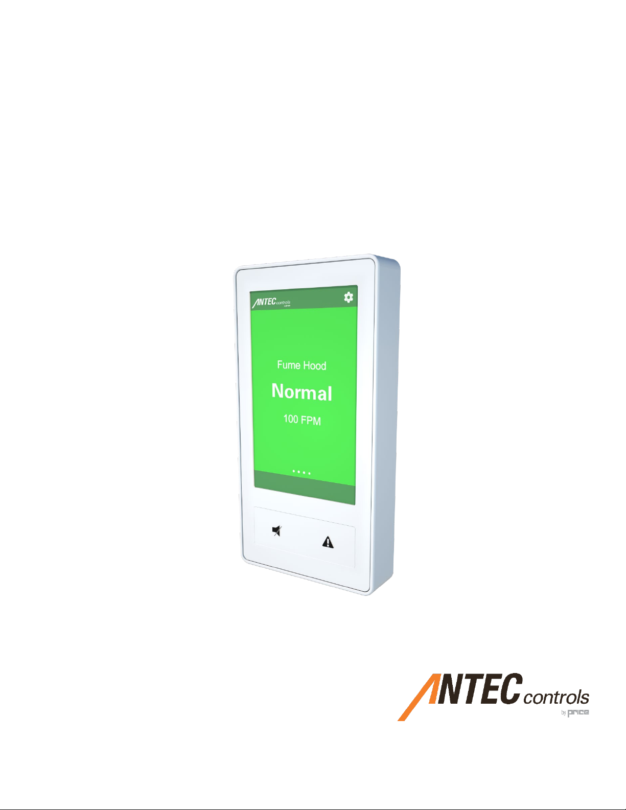
Cava™ displays critical fume hood details through its interface, where
users can effortlessly view real-time information and update a variety
of display parameters. Fume hood status is clearly indicated through a
colored display with an excellent viewing angle, along with
programmable audible alarms ensuring the safety of all users through
immediate notification of changes in fume hood status. Cava™ has
two physical buttons, including one that allows users to quickly enter
emergency mode without having to remove any protective wear.
Features
•4.3” capacitive touchscreen display
•Large tactile buttons for ‘glove-handed’ use
•Audible and visual configurable alarms
•Works with Venturi Valves, Venturi FX Valves, and terminal units
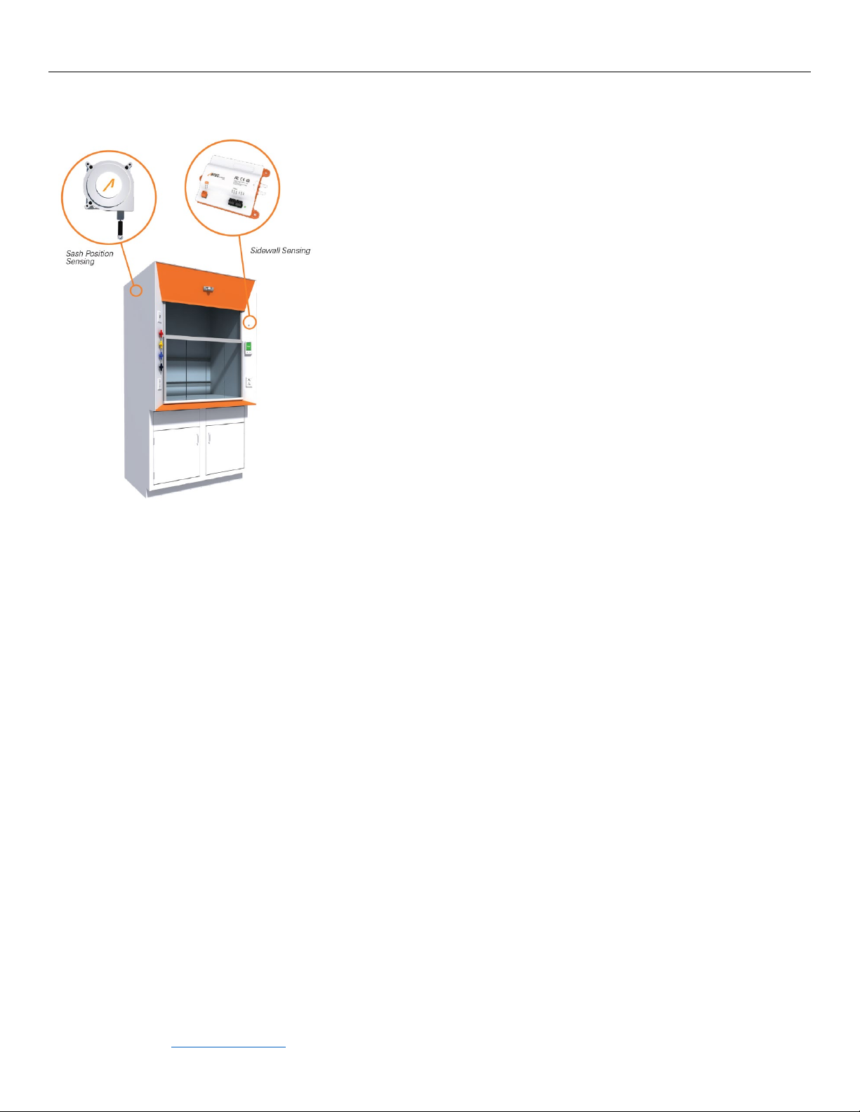
•Sash position sensing, sidewall face velocity sensing, or hybrid
sensing configuration
•Less than 1 second speed of response defined by ANSI Z9.5
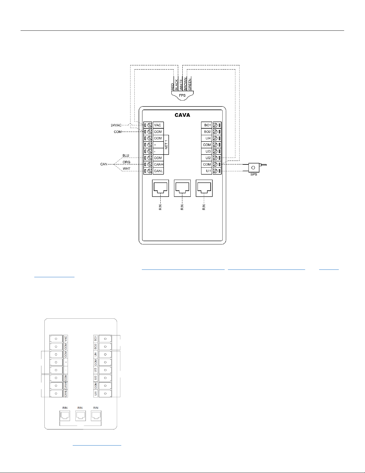
•Controller Area Network (CAN) for communication between
fume hood-level devices
•High-speed Room Information Network (RIN) for communication
between all room level and fume hood controllers
•BACnet MS/TP
•Fast, intuitive start-up and balancing software
•User defined fume hood modes
•Commissioning port at every Cava™ that allows for simple fume
hood and room level setup
Installation & Service
1. A qualified person must perform installation
and electrical wiring in accordance with all
applicable codes and standards, including
fire-rated construction practices.
2. Do not damage electrical wiring and other
hidden utilities while installing this device.
3. Disconnect power at the service panel
before performing wiring or maintenance
on this device.
4. Intended for indoor installation only, in
areas with Pollution Degree 3.
5. Not designed for use in industrial, farming,
or humid environments.
6. Not designed for use in residential
environments and may not have adequate
protection to radio interference.
7. Not designed to operate in a construction
environment. Use in these environments
may lead to excess or unintended wear,
reducing product life and/or performance.
This mark indicates an important point for
the proper function of Cava™ and any of its
accessories. Pay close attention to all
caution points throughout this manual.
CAUTION
For support and in-depth
training on this product and
other associated system
components, please
contact your local Antec
Controls Representative.
For more information visit
www.AntecControls.com

CAVA - MANUAL
1 | CAVA – Manual | AntecControls.com
Technical Specifications
Environmental
(Operating)
32°F to 130°F (0°C to 55°C), 5% to 95% R.H. (Non-Condensing)
Environmental
(Storage)
-22°F to 158°F (-30°C to 70°C), 0% to 95% R.H. (Non-Condensing)
Input Power
24 VAC ±10%, 50/60 Hz, 12 VA Max (excluding external loads), Class 2
Inputs
4 Universal Inputs (Includes sidewall
and sash-position sensor inputs)
Binary Input (Contact Closure or Active)
Analog Input (0 – 10 VDC)
Resistance Input – Sash Position (0 – 50 kΩ)
Control Area Network (CANbus)
3 Room Information Network (RIN) Ethernet Ports
RS-485 Network (BACnet)
Outputs
2 Binary Outputs (Max: 24 VAC, 500 mA)
Indicators
4.3” LCD Capacitive Touch Screen
Audible Alarm
Buttons
Mute Alarm
Emergency Mode
Housing
UL 94V-0, PC-ABS Plastic
Communication
Protocol
BACnet
BACnet
Device Type
B-AAC
Communication Type
MS/TP (RS-485)
Communication Speed
9600, 19200, 38400, 76800 Baud Rate
Certification
BTL
Control Priority Order
1. BACnet
2. Normal operation

CAVA - MANUAL
2 | CAVA – Manual | AntecControls.com
Sash, Sidewall & Hybrid Configuration
Control Settings
No Control – Monitor Only
This method disables all control. The device will only monitor the face velocity of the fume
hood / cabinet using a Sash Position Sensor and/or a Sidewall Velocity Sensor, but will not
change its airflow or face velocity.
Sash Position Control
This method calculates the face velocity using the dimensions of the fume hood opening and
the current CFM. This method will control face velocity.
Sidewall Face Velocity Control
This method measures the face velocity over the sash opening by measuring the pressure
inside the fume hood. This method will control face velocity.
Hybrid Control
This method is an optimized combination of both sidewall face velocity control and sash
position control. It is the most effective method of fume hood control and is recommended
in all cases. Hybrid Control is only available if both a sidewall velocity sensor and a sash
position sensor are connected.

CAVA - MANUAL
3 | CAVA – Manual | AntecControls.com
MECHANICAL INSTALLATION
It is recommended to mount Cava™ at approximately 5½’ to 6’ from the floor. This will allow the interface to be at an
appropriate height for use during setup and during normal operation.
Mounting Options
Cava™ can be mounted in one of three ways. Option A uses a pre-cut single gang junction box cut-out. Option B uses an on-
site created cut-out using a Jigsaw. Option C uses an on-site created circular cut-out.
Option A
Mount Cava™ using a pre-cut single gang junction box cut-out.
STEP 1
Mount the backplate to the fume hood using four #6 self-tapping metal screws (minimum 3/8”
long).
STEP 2
Attach Cava™ and tighten the set screw once electrical installation is complete.
Option B
Mount Cava™ using a Jigsaw cut-out.
STEP 1
Mark the appropriate mounting location for Cava™.
STEP 2
Drill two 1/4” to 1/2” pilot holes at either corner of the provided template in Appendix A.
STEP 3
Using a jigsaw, cut four lines to cut-out a square.
STEP 4
Drill four 7/64” mounting holes according to the provided template in Appendix A.
STEP 5
Deburr and file any sharp edges if they are present to prevent any edges from cutting the
wiring.
STEP 6
Mount the backplate to the fume hood using four #6 self-tapping metal screws (minimum 3/8”
long).
STEP 7
Attach Cava™ and tighten the set screw once electrical installation is complete.
Option C
Mount Cava™ using a circular cut-out. This is the least preferable mounting option, as the
hole provides the least access to the wiring terminals.
STEP 1
Mark the appropriate mounting location for Cava™.
STEP 2
Drill a 2.25” hole in the front panel of the fume hood according to the provided template in
Appendix A.
STEP 3
Drill four 7/64” mounting holes according to the provided template in Appendix A.
STEP 4
Deburr and file any sharp edges if they are present to prevent any edges from cutting the
wiring.
STEP 5
Mount the backplate to the fume hood using four #6 self-tapping metal screws (minimum 3/8”
long).
STEP 6
Attach Cava™ and tighten the set screw once electrical installation is complete.
There are often disconnect switches and gas/water lines running in the fume hood. Make sure that the marked location for
the interface does not conflict with any of the other components that may be installed on/in the fume hood. When cutting
and drilling holes in the fume hood, ensure proper precautions are taken to avoid scuffing or scratching the fume hood.
CAUTION

CAVA - MANUAL
4 | CAVA – Manual | AntecControls.com
ELECTRICAL INSTALLATION
Wiring
NOTES:
1. For Typical Network Wiring Diagrams, see Room Information Network (RIN), Controller Area Network (CAN), and BACnet
MS/TP Network sections.
2. All wire connections to the Cava™ screw connection terminals must be between 16-26 AWG wire.
3. Current and voltage drop should be taken into consideration when selecting wire gauge.
4. Wiring above may not reflect those required for your project. Refer to your Antec Controls Wiring Diagram Package for
typical wiring recommendations.
Input / Output Usage
A
Cava™ has native BACnet capabilities, with the connection being made through the NET 1
terminals.
B
Cava™ can connect to the Fume Hood Valve Module (FVM) and the Sidewall Velocity
Sensor (SVS) through the Controller Area Network (CAN) terminals.
C
Cava™ can provide a switchable ground binary signal based on a variety of variables and
inputs.
NOTE: The high side of the device should be connected to a 24VAC supply, and the
common of the device should be connected to a Binary Output terminal.
D
Cava™ includes Universal Inputs that can be any of the following:
•Binary Input (Contact Closure or Active)
•Analog Input (0 to 10 VDC)
•Resistance Input (0-50 kΩ)
Universal Inputs are generally used to connect Sash Position Sensors (SPS) or Fume Hood
Presence Sensors (FPS).
E
The Ethernet Ports can be used to connect Cava™ to other room devices through the Room
Information Network (RIN) and used for setup or service.
A
B
C
D
E

CAVA - MANUAL
5 | CAVA – Manual | AntecControls.com
Room Information Network (RIN)
What is the Room Information Network?
The Antec Controls Pace™ and Cava™ operate on a
distributed network called the Room Information Network
(RIN). Together, the Pace™ controllers operating in the
room will work to control room levels functions such as
temperature control, room occupancy, and room
pressurization. When used with Cava™, the fume hood
flows, face velocities, and status will be reported to the
room level controllers to ensure all room demands for
safety are being met.
Antec Toolbox also uses RIN for room level and fume hood
configuration. The user will connect to RIN to communicate
with each Pace™ and Cava™ to configure their
functionality.
Network Addressing
All Cava™ devices will come from the factory with
predefined MAC addresses. If a Fume Hood Valve Module
(FVM) is connected during Cava™ setup, the device will
populate with a unique name based on the valve tag in the
FVM’s linestring. If no FVM is connected, or a different
naming convention is required, the name is customizable
from the settings menu.
Physical Connection
RIN consists of a 4-wire network architecture (RX-, RX+,
TX-, TX+) using a daisy-chain connection between each
device on the network segment. A RIN segment has a limit
of:
•24 total RIN devices (Pace™ and Cava™)
•16 Cava™ devices
•A maximum length of 150 feet (45 meters)
between each device.
Users will require an Ethernet Port or a USB-A to Ethernet
dongle to connect a laptop to RIN for configuration.
Wiring Requirements
Refer to your Antec Controls Wiring Diagram Package for
typical wiring requirements and recommendations.
Typical RIN Wiring

CAVA - MANUAL
6 | CAVA – Manual | AntecControls.com
Controller Area Network (CANbus)
What is the Controller Area Network?
The Controller Area Network (CANbus) is a communication
protocol that allows the Fume Hood Valve Module (FVM)
and the Sidewall Velocity Sensor (SVS) to communicate
with Cava™. By transmitting data from the SVS to Cava™
at high speeds and relaying changes to the FVM, Cava™
can ensure that the fume hood is always in safe operating
conditions.
Network Addressing
CANbus devices will come from the factory with
predefined MAC addresses. No addressing on-site is
required.
Physical Connection
CANbus consists of a 3-wire network architecture. Daisy
chain the CANH, CANL, and COM connections of all
devices on the network as shown below. A CANbus
segment has a limit of:
•3 Sidewall Velocity Sensors (SVS)
•1 Fume Hood Valve Module (FVM)
•A maximum length of 650 feet (200 meters) for the
whole segment
When using shielded cable, ground the shield at one end of
the network segment only. Connect the shield of the cable
entering a device to that of the cable exiting the device.
Terminate the network at the end of line CANbus device by
connecting a 120 ohm resistor between the CANH and
CANL network terminals. The network may fail to function
without the 120 ohm resistors in place. Remove the
termination resistor when adding devices to an existing
network and re-install it on the new end of line device.
NOTE: Cava™ has a built-in end of line resistor for CANbus
and must be an end of line device.
Wiring Requirements
Refer to your Antec Controls Wiring Diagram Package for
typical wiring requirements and recommendations.
Typical CAN Wiring
NOTE:Installer must use a 120 ohm resistor at the CANbus end of line termination.
When using non-isolated power supplies (i.e.
Transformer secondary common connected to
ground), do not reverse 24VAC polarity on any
device, as it is critical to the network health.
CAUTION

CAVA - MANUAL
7 | CAVA – Manual | AntecControls.com
BACnet MS/TP Network
NOTE: BACnet is only used on Cava™ when it does not
have a RIN connection to a Pace™ controller in the room.
What is BACnet?
BACnet MS/TP is a communication protocol for
communication between Cava™ and the building
automation network. BACnet communication allows the
end user to verify rooms and fume hoods are operating as
expected and allows them to set up trends to monitor
safety, and any alarms that occur.
If no Pace™ controllers are present in the space, a single
Cava™ in the room can act as the access point to BACnet.
All of the fume hood’s information transmits through this
one Cava™ to the network.
Network Addressing
When configuring Cava™, the user needs to assign the
unique identifying address for the room.
On any BACnet MS/TP network:
•MAC Address can be between 0 and 127 and must be
unique to the MS/TP segment.
•Device Instance can be between 0 and 4,194,303 and
must be unique to the facility.
•Baud Rate can be 9,600, 19,200, 38,400, or 76,800
and must match that of the Router/System Controller
for the MS/TP segment.
BACnet Points
See Cava™ Product Submittal at AntecControls.com for
BACnet Points List.
Physical Connection
BACnet consists of a 3-wire network architecture. Daisy
chain the +, -, and COM connections of all devices on the
network segment. A BACnet MS/TP segment has a limit
of:
•Maximum of 32 devices
•Maximum length of 1050 feet (320 meters) for the
whole segment
When using shielded cable, ground the shield at one end of
the network segment only. Connect the shield of the cable
entering a device to that of the cable exiting the device.
Terminate the MS/TP network segment at each end of the
network segment by connecting a 120-ohm resistor
between the + and – terminals. Remove the termination
resistor or disable any network terminations on all devices
when adding devices to an existing network segment.
Wiring Requirements
Refer to your Antec Controls Wiring Diagram Package for
typical wiring requirements and recommendations.
Typical BACnet Wiring
NOTE: Installer must use a 120 ohm resistor at the BACnet end of line termination.
When using non-isolated power supplies (i.e. Transformer
secondary common connected to ground), do not reverse 24VAC
polarity on any device, as it is critical to the network health.
CAUTION

CAVA - MANUAL
8 | CAVA – Manual | AntecControls.com
Network Architecture Summary
See the information outlined in the example below for a summary of the network architecture of Cava™.
Typical Laboratory Wiring
Line Color Network Type Considerations
Blue Room Information Network (RIN) Up to 24 controllers (PACE and CAVA combined), with a maximum of 16 CAVAs
Daisy chained network wiring between each device on the network
NOTE: A connection through a RIN access point is used to start-up and commission the
system. An Ethernet Port on the back of any CAVA can act as this access point.
Green Controller Area Network (CAN) Maximum of 3 Sidewall Velocity Sensors (SVS)
Maximum of 1 Fume Hood Valve Module (FVM)
Daisy chained network wiring between each device on the network
Red BACnet MS/TP Recommended up to 32 devices (including CAVA, PACE, PMT, MVM, or 3rd party)
One BACnet network is allowed per RIN
Daisy chained MS/TP segment only connects through one PACE (or CAVA if no PACE is
present) controller per room

CAVA - MANUAL
9 | CAVA – Manual | AntecControls.com
FUME HOOD ACCESSORIES
Cava™ can take advantage and multiple fume hood accessories to
effectively monitor and control fume hood face velocity, reduce
energy consumption, and keep work environments safe.
Fume hood accessories provided by Antec Controls include:
1. Fume Hood Valve Module (FVM) - Venturi Valve (VV) Applications
2. Fume Hood Valve Module (FVM) - Venturi FX Valve (VFX) and
Terminal Unit (TU) Applications
3. Sash Position Sensor (SPS)
4. Sidewall Velocity Sensor (SVS)
5. Fume Hood Presence Sensor (FPS)
Fume Hood Valve Module (FVM) - Venturi Valve (VV) Applications
The Fume Hood Valve Module (FVM) works directly with Cava™ to accurately meet
the required exhaust airflow and fume hood face velocity. The FVM used in Venturi
Valve applications uses calibrated position feedback to provide accurate airflow
through the valve and provides real-time differential pressure readings to ensure the
valve remains within its operating parameters at all times. The FVM delivers this
real-time airflow device information to Cava™ for display and communication over
CANbus.
See the FVM product submittal on AntecControls.com for Specifications,
Dimensions, and Wiring.
Mechanical Installation
Overview
The FVM is factory calibrated and mounted on the valve with which it was ordered. Only
electrical installation is required. Open the controls enclosure on the valve and follow the
wiring diagram in the project submittals for electrical installation.
Components
A
4 Analog Outputs (0 to 10 VDC, 10 mA Max. Each connected actuator requires 1 output)
B
2 Potentiometer terminals (unique to Venturi Valve applications)
C
Terminal Block to be connected to 24VAC power source (50/60 Hz, 17 VA Max)
D
High-pressure port
E
Low-pressure port
F
Indicator LED
G
CANbus terminal for connection to CAVA and other CANbus devices
H
Fume Hood Valve Module (FVM) pre-installed in fume hood valve enclosure
NOTE:The FVM is factory mounted within the enclosure using #8 x 5/16 in. screws through
three mounting holes.
NOTE:The maximum torque rating for any bushings on the enclosure is 4.43 in·lbs (0.5 N·m).
Different types of fume hood accessories
can be used with Cava™. When using
accessories by Others, ensure that the
output from or input to the device meets
the requirements of the inputs and outputs
on Cava™ which can be found on Page 1.
CAUTION
A
C
D
E
F
G
H
B

CAVA - MANUAL
10 | CAVA – Manual | AntecControls.com
Electrical Installation
Indicator Color
Description
Solid Green
Device is functioning properly
Blinking Green
Used for ping identification
Solid Magenta
Incompatible firmware
NOTES:
1. For Typical CAN Wiring Diagrams, see Controller Area Network (CAN) section.
2. All wire connections to the FVM screw connection terminals must be between 16-26 AWG wire.
3. Current and voltage drop should be taken into consideration when selecting wire gauge.
4. Wiring above may not reflect those required for your project. Refer to your Antec Controls Wiring Diagram Package for
typical wiring recommendations.
POT1 and POT2 terminations
Wire Color
FVM
Terminal
Red
+
Green
SIG
Black
-
CAUTION

CAVA - MANUAL
11 | CAVA – Manual | AntecControls.com
Fume Hood Valve Module (FVM) - Venturi FX Valve (VFX) and Terminal
Unit (TU) Applications
The Fume Hood Valve Module (FVM) works directly with Cava™ to accurately meet
the required exhaust airflow and fume hood face velocity. The FVM used in Venturi
FX Valve (VFX) and Terminal Unit (TU) applications uses high-accuracy pressure
readings to measure the airflow through the valve. The FVM delivers this real-time
airflow device information to Cava™ for display and communication over CANbus.
See the FVM product submittal on AntecControls.com for Specifications,
Dimensions, and Wiring.
Mechanical Installation
Overview
The FVM is factory calibrated and mounted on the valve with which it was ordered. Only
electrical installation is required. Open the controls enclosure on the valve and follow the
wiring diagram in the project submittals for electrical installation.
Components
A
4 Analog Outputs (0 to 10 VDC, 10 mA Max. Each connected actuator requires 1 output)
B
Terminal Block to be connected to 24VAC power source (50/60 Hz, 17 VA Max)
C
High-pressure port
D
Low-pressure port
E
Indicator LED
F
CANbus terminal for connection to CAVA and other CANbus devices
G
Fume Hood Valve Module (FVM) pre-installed in fume hood valve enclosure
NOTE: The FVM is factory mounted within the enclosure using #8 x 5/16 in. screws through
three mounting holes.
NOTE: The maximum torque rating for any bushings on the enclosure is 4.43 in·lbs (0.5 N·m).
A
B
C
D
E
F
G

CAVA - MANUAL
12 | CAVA – Manual | AntecControls.com
Electrical Installation
Indicator Color
Description
Solid Green
Device is functioning properly
Blinking Green
Used for ping identification
Solid Magenta
Incompatible firmware
NOTES:
1. For Typical CAN Wiring Diagrams, see Controller Area Network (CAN) section.
2. All wire connections to the FVM screw connection terminals must be between 16-26 AWG wire.
3. Current and voltage drop should be taken into consideration when selecting wire gauge.
4. Wiring above may not reflect those required for your project. Refer to your Antec Controls Wiring Diagram Package for
typical wiring recommendations.

CAVA - MANUAL
13 | CAVA – Manual | AntecControls.com
Sash Position Sensor (SPS)
The Sash Position Sensor (SPS) reports the open area of the fume hood by
measuring the sash location. Cava™ uses the SPS measurement to adjust the
exhaust airflow based upon the measured sash opening. The SPS contains a long-
life potentiometer (over 250,000 cycles) and is constructed using a stainless-steel
cable for stability and a thick plastic cover for protection against airborne chemical
agents.
See the SPS product submittal on AntecControls.com for Specifications,
Dimensions, and Wiring.
Mechanical Installation
The SPS can be mounted in one of four ways. Options A mounts to the counterweight system, Option B mounts directly above
the sash outside of the fume hood, Option C also mounts to the counterweight system, and Option D mounts directly in the
hood.
Option A
Mount the SPS on the top of the fume hood.
STEP 1
Ensure the cable clamp does not pass around a pulley.
STEP 2
Run the sensor cable back to the CAVA mounted on the front of the fume hood and connect it
to a Universal Input (see Electrical Installation section).
STEP 3
Ensure the sensor cable travels parallel to the counterweight cable.
Option B
Mount the SPS above the sash.
STEP 1
Ensure the cable is free from obstruction along the entire length of sash movement.
STEP 2
Ensure that the mounting position of the end of the cable will not pass above the SPS even at
the maximum sash height.
STEP 3
Run the sensor cable back to the CAVA mounted on the front of the fume hood and connect it
to a Universal Input (see Electrical Installation section).
The Sash Position Sensor cable must be mounted as close to parallel as
possible with the direction of the sash movement.
CAUTION

CAVA - MANUAL
14 | CAVA – Manual | AntecControls.com
Option C
Mount the SPS on the top of the fume hood.
STEP 1
Ensure the cable is free from obstruction along the entire length of sash movement.
STEP 2
The sensor cable may be attached directly to the counterweight. This configuration may be
desired when the sash connects to the counterweight with a belt and pulley system.
STEP 3
Run the sensor cable back to the CAVA mounted on the front of the fume hood and connect it
to a Universal Input (see Electrical Installation section).
Option D
Mount the SPS on the inside wall of the fume hood. This is the least preferable mounting
option, as the sensor is directly in the exhaust air stream.
STEP 1
Ensure that the sensor and cable do not interfere with the mechanical operation of the fume
hood sash.
STEP 2
Ensure the sensor is as close to the sash as possible so that the cable is completely parallel to
the sash in all positions.
STEP 3
Raise the sash to the fully open position (not just the working height). Screw the metal ring into
the sash. Ensure that the sensor is mounted higher than the fully open position of the sash.
STEP 4
Once mounted, raise and lower the sash several times to ensure that the cable is clear of all
obstructions and moves freely with the sash.
STEP 5
Run the sensor cable back to the CAVA mounted on the front of the fume hood and connect it
to a Universal Input (see Electrical Installation section).

CAVA - MANUAL
15 | CAVA – Manual | AntecControls.com
Sidewall Velocity Sensor (SVS)
The Sidewall Velocity Sensor (SVS) reports face velocity to Cava™ by measuring
the differential pressure between the fume hood and the laboratory. Cava™ uses
the SVS measurement to adjust the exhaust to meet the required face velocity. The
SVS consists of multiple components:
•Sidewall Velocity Sensor (SVS)
•1’ x 3.5” 3M Dual Lock Fastener
•Two brass bulkheads with vent screws
•Two 1.5-foot lengths of high-pressure tubing
See the SVS product submittal on AntecControls.com for Specifications,
Dimensions, and Wiring.
Mechanical Installation
The SVS can be mounted in one of three locations. Option A mounts on top of the fume hood, Option B mounts in the side
panelling (chase) of the fume hood, and Option C mounts in the front panelling of the fume hood.
Mounting options may be limited by tubing length and vent screw locations. It is recommended to select the mounting location
which minimizes tubing length, and to keep in mind the following considerations when selecting a location.
Option A
Mount the SVS on top of the fume hood.
•Tubing runs over the top of the fume hood and down the side panelling (chase) and
should not exceed 2 feet.
•Must ensure tubing and wiring do not interfere with the mechanical operation of the
fume hood sash.
Option B
Mount the SVS in the side panelling (chase) of the fume hood.
•Exterior wall of chase is often removable for maintenance. If sensor is mounted to
this wall, it will need to be disconnected for removal.
•Ideal mounting location is on interior wall above the inside wall access panel.
Option C
Mount the SVS in the front panelling of the fume hood.
•Tubing runs from front panelling to side panelling, which may require passthrough
holes to be drilled depending on fume hood design.

CAVA - MANUAL
16 | CAVA – Manual | AntecControls.com
Regardless of where the SVS is mounted, the following steps outline how to install the SVS components.
STEP 1
With the sash in the fully open position, drill a 5/16” hole 5” above and 5” inward from the
base of the sash.
STEP 2
Drill a 5/16” hole on the front of the fume hood on the same side as the first hole.
STEP 3
Mount the brass bulkheads to the fume hood through the holes.
STEP 4
Select one of the three mounting options on the previous page for the SVS and mount using
one of the two methods outlined below:
For 3M Dual Lock Fastener mounting (recommended), clean the mounting surface and
the back of the sensor with a cloth or IPA. Wait 5 minutes for IPA to evaporate if used. At
room temperature, peel backing from one side of the 3M fastener and apply it to the back of
the sensor. Peel backing from opposite side of the 3M fastener and firmly press the SVS and
3M fastener onto the mounting surface for 30 seconds.
For screw mounting, place sensor in desired location and mark the three mounting hole
locations on the fume hood. Drill three 1/8” pilot holes in the appropriate locations on the
fume hood. Mount sensor using three #8 x 5/16 in. screws.
STEP 5
Use the high-pressure tubing to connect the outer brass bulkhead to the high-pressure port
of the sensor. Do the same to connect the inner brass bulkhead to the low-pressure port of
the sensor.
Mounting position is critical to ensure the accuracy of the SVS.
Ensure that there are no sharp bends or kinks in the tubing during
the installation. Improper installation will cause failure of the SVS.
CAUTION

CAVA - MANUAL
17 | CAVA – Manual | AntecControls.com
Electrical Installation
Indicator Color
Description
Solid Green
Device is functioning properly
Blinking Green
Used for ping identification
Solid Magenta
Incompatible firmware
NOTES:
1. For Typical CAN Wiring Diagrams, see Controller Area Network (CAN) section.
2. All wire connections to the SVS screw connection terminals must be between 16-26 AWG wire.
3. Current and voltage drop should be taken into consideration when selecting wire gauge.
4. Wiring above may not reflect those required for your project. Refer to your Antec Controls Wiring Diagram Package for
typical wiring recommendations.
Table of contents
Other Price Controllers manuals
Popular Controllers manuals by other brands

Mitsubishi Electric
Mitsubishi Electric FX3UC-4AD installation manual

Cognex
Cognex VisionPro Trevista CI Dome Installation and operation manual

Beckhoff
Beckhoff C6920 Installation and operating instructions

Danfoss
Danfoss OBC 80 Series manual

Tescom
Tescom 44-4600 Series Instructions for use

Pandrive
Pandrive PD42-1270 TMCL Firmware user manual