Price UMC3 Series User manual

MANUAL – INSTALLATION + SERVICE
Underfloor ModuFlex Controller
UMC3 Series
v100 –Issue Date: 09/20/17
© 2017 Price Industries Limited. All rights reserved.

UNDERFLOOR MODUFLEX CONTROLLER
TABLE OF CONTENTS
Product Overview
Introduction................................................................... 1
General Safety Guidelines..............................................1
Safety Precautions ....................................................... 1
Safety Symbols ............................................................. 1
Underfloor Systems Control Zones................................ 2
General Description....................................................... 3
Features of the UMC3 ................................................... 4
Operation ...................................................................... 4
Installation & Mounting Instructions
Installation ..................................................................... 5
Price Flow Response Chart ........................................... 5
Input/Output Description ............................................... 6
Wiring ........................................................................... 7
Thermostat Installation .................................................. 8
How to use Thermostats ............................................... 9
Display Navigation
Initial Startup ............................................................... 10
Service Menu .............................................................. 11
Balancing Menu .......................................................... 12
VVT Menu ................................................................... 13
Setpoint Menu............................................................. 14
Input Menu.................................................................. 15
Output Menu - Aux Binary........................................... 16
Output Menu - Analog Outputs ................................... 17
Stat Setup Menu ......................................................... 18
Info Menu.................................................................... 19
Address Menu............................................................. 20
Networking & Setup
BACnet Networking and Setup ................................... 21
Setting the Device Instance ......................................... 22
LINKER - USB Service Tool ......................................... 23
Maintenance
Troubleshooting........................................................... 24
Hardware Specifications.............................................. 25

1
priceindustries.com |UNDERFLOOR MODUFLEX CONTROLLER - Manual
UNDERFLOOR MODUFLEX CONTROLLER
PRODUCT OVERVIEW
Introduction
In this manual, you will find technical descriptions and
diagrams of underfloor system components along with
their installation instructions. Practical guidelines and
recommendations are also provided. If more information is
required about this equipment, please contact a Price sales
representative.
General Safety Guidelines
This document is intended for use by owner-authorized
operating/service personnel who are expected to possess the
required training to enable them to perform their tasks properly
and safely. This individual must have read and understood this
document and any referenced materials prior to performing any
task on this equipment. Also, it is essential that this individual
be familiar with and comply with all applicable governmental
standards and regulations pertaining to the task in question.
This individual must also verify that installation and connections
comply with local building codes. It is the obligation and
responsibility of the operating/service personnel to identify and
recognize these inherent hazards, protect themselves, and
proceed safely in completing their tasks. Failure to comply
with any of these requirements could result in severe personal
injury or death to themselves and people at the site, as well as
serious damage to the equipment and the property in which it
is situated.
The equipment discussed in this manual is relatively
complicated apparatus and must be handled with the
necessary precautions. Individuals may be exposed to certain
components or conditions such as refrigerants, oils, materials
under pressure, rotating components, and both high and low
voltage during installation, operation, maintenance or service
of this equipment. If misued or mishandled, each item has the
potential to cause bodily injury or death.
Safety Precautions
When using electrical appliances, basic safety precautions
should always be followed including the following:
1. Read all instructions.
2. Do not touch hot surfaces.
3. To protect against electrical shock do not immerse cord,
plugs, or Control Box in water or other liquids.
4. Unplug the unit when not in use and before cleaning.
5. Do not operate any appliance with a damaged cord or
plug or after the appliance malfunctions or has been
damaged in any manner. Return appliance to the nearest
authorized service facility for examination, repair or
adjustment.
6. The use of accessory attachments not recommended by
the appliance manufacturer may cause injuries.
7. Do not use outdoors.
8. Do not let cord hang over edge of a table or counter, or
touch hot surfaces.
9. Do not place on or near a hot gas or electric burner, or in a
heated oven.
10. Always attach plug to appliance first, then plug into the
power source. To disconnect, turn any control to “off”,
then remove plug from power source.
11. Do not use appliance for other than intended use.
12. Save these instructions.
Safety Symbols
The following symbols are used in this document to alert the
reader to areas of potential hazard:
CAUTION
Failure to observe may result in equipment damage.
WARNING
Failure to observe may result in personal injury, death or
equipment damage.
NOTE: Used to highlight additional information helpful to the reader.

2UNDERFLOOR MODUFLEX CONTROLLER - Manual |priceindustries.com
UNDERFLOOR MODUFLEX CONTROLLER
Product overview
Underfloor Systems Control Zones
INTERIOR ZONES
Constant Air Volume - Cooling Only
Typically, interior zones have relatively stable loads hence
constant volume supply is often employed. A typical interior
zone consists of contant volume or constant pressure turbulent
floor twist outlets installed in a large, common plenum space.
In this method the entire plenum space is treated as one zone
and, under fluctuating loads, the amount of air delivered to
the space is regulated by the relative pressure in this plenum,
modulated by a single point of control. Manual face-adjustable
diffusers (MFD) provide occupant control of airflow volume.
Variable Air Volume - Cooling Only
In the case an open plenum is desired to be divided into
several zones, variable air volume control is possible with the
use of devices installed under the diffuser or with the use of a
variable volume basket. The variable volume diffusers would
be controlled by the UMC. The UMC would open and close
the diffusers releasing air from the pressurized plenum. The
variable volume (VAV) diffusers require a 24 VAC signal which is
provided by the UMC to modulate the actuators. Meanwhile,
the UMC accepts a 0 to 10 VDC cooling signal either from
a manual control signal or from a thermostat. The UMC
modulates the airflow from 0% to 100%.
PERIMETER ZONE
Trough Heating and Cooling
Use of linear floor grilles with integrated heating elements offer
a system with heightened flexibility and efficiency as it omits
the use of fan terminal units and ducting. In cooling mode,
dampers on the LFGH modulate open to the plenum allowing
more airflow into the space to satisfy the cooling demand.
When a call for heat arises, the hot water or electric coil
energizes and the diffusers either open to the plenum or to a
perimeter cavity to allow air to pass over the heating element.
LFGHs are controlled by the UMC3 where up to 12 LFGHs can
be daisy chained.
TROUGH HEATING AND COOLING
CONSTANT AIR VOLUME - COOLING ONLY
VARIABLE AIR VOLUME - COOLING ONLY

3
priceindustries.com |UNDERFLOOR MODUFLEX CONTROLLER - Manual
UNDERFLOOR MODUFLEX CONTROLLER
PRODUCT OVERVIEW
General Description
The Third Generation Underfloor ModuFlex Controller (UMC3) is a direct digital controller for pressurized underfloor plenum cooling
zones. It can control up to 30 underfloor damper/diffusers – 12 of which can be the LFGH with integrated reheat. Auxiliary inputs
and outputs add to the UMC3’s flexibility.
The UMC3 offers cutting edge zone control by combining the accuracy of direct digital control with the flexibility of an individual
zone control system; providing maximum control and efficiency. An advanced and configurable proportional integral controller
allows for exceptional user comfort and energy efficiency. Installation of the controller and thermostat is simple and error proof with
RJ-45 (network type) connections to the thermostat and BACnet network.
The UMC3 comes factory mounted in a rugged galvanized enclosure complete with a 96VA transformer and disconnect switch.
METAL SAFETY GUARD
SEPARATING HIGH AND
LOW VOLTAGE AREAS
96 VA MULTI-TAP
TRANSFORMER WITH
CIRCUIT BREAKER
DISCONNECT SWITCH
8 GROMMETED
OPENINGS FOR MODULAR
CABLE CONNECTIONS
THERMISTOR INPUT
(MONITORING ONLY) VOLTAGE TEST POINTS
RJ-45 T-STAT PORT FOR
THERMOSTAT CONNECTION
PLUGGABLE 24VAC
POWER TERMINAL
BACNET MS/TP CONNECTIONS
COMMON BINARY OUTPUTS
AUX
DAMPER CLOSED
DAMPER OPEN
BACNET MAC ADDRESS
LED INDICATORS FOR
TROUBLESHOOTING
ANALOG INPUTS
PIN 1 – COOLING
PIN 2 – HEATING
ANALOG OUTPUTS
HEAT
AUX
COM
LFGH OUTPUTS
CONNECT UP TO 6 LFGH UNITS
PER JACK FOR A TOTAL OF 12
LFGH UNITS
MODULAR DAMPER OUTPUTS
CONNECT UP TO 6 UNDERFLOOR
DAMPERS/DIFFUSERS PER JACK
FOR A TOTAL OF 30 DAMPERS/
DIFFUSERS (INCLUDING LFGH)

4UNDERFLOOR MODUFLEX CONTROLLER - Manual |priceindustries.com
UNDERFLOOR MODUFLEX CONTROLLER
Product overview
Features of the UMC3
• Control up to 30 underfloor dampers.
• Modular connections to dampers – Use RJ-12 cables
included with dampers to connect underfloor dampers to
UMC3. LFGH dampers use RJ-45 connections.
• Outputs protected by self-resetting thermal fuses – Prevents
damage to circuit board in the event of a damaged cable.
Fault LED lights when dampers are trying to drive on an
output with damaged cable.
• Auxiliary 24VAC Binary Output – Use for reheat, room lights,
signal to other equipment, etc. Rated for a maximum output
of 0.5A (12VA).
• Auxilary Analog Outputs (2) – Use to connect to other
equipment, BAS, etc. Output range fully configurable (2-
10VDC, 0-10VDC, 10-2VDC, etc.). Rated at a maximum
output of 10mA each.
• Analog Inputs (2) – Configurable to allow control of the
UMC3 from a source other than a Price Thermostat (BAS,
third party thermostat, etc.). Accepts the standard dual
0-10VDC signal for cooling/heating. (if not using LFGH or
other heaters connected to UMC3, only the 0-10V cooling
signal is needed).
• Input (1) 10K type J thermistor – Can be used to monitor a
temperature over the network. Can also be used for heat/
cool changeover.
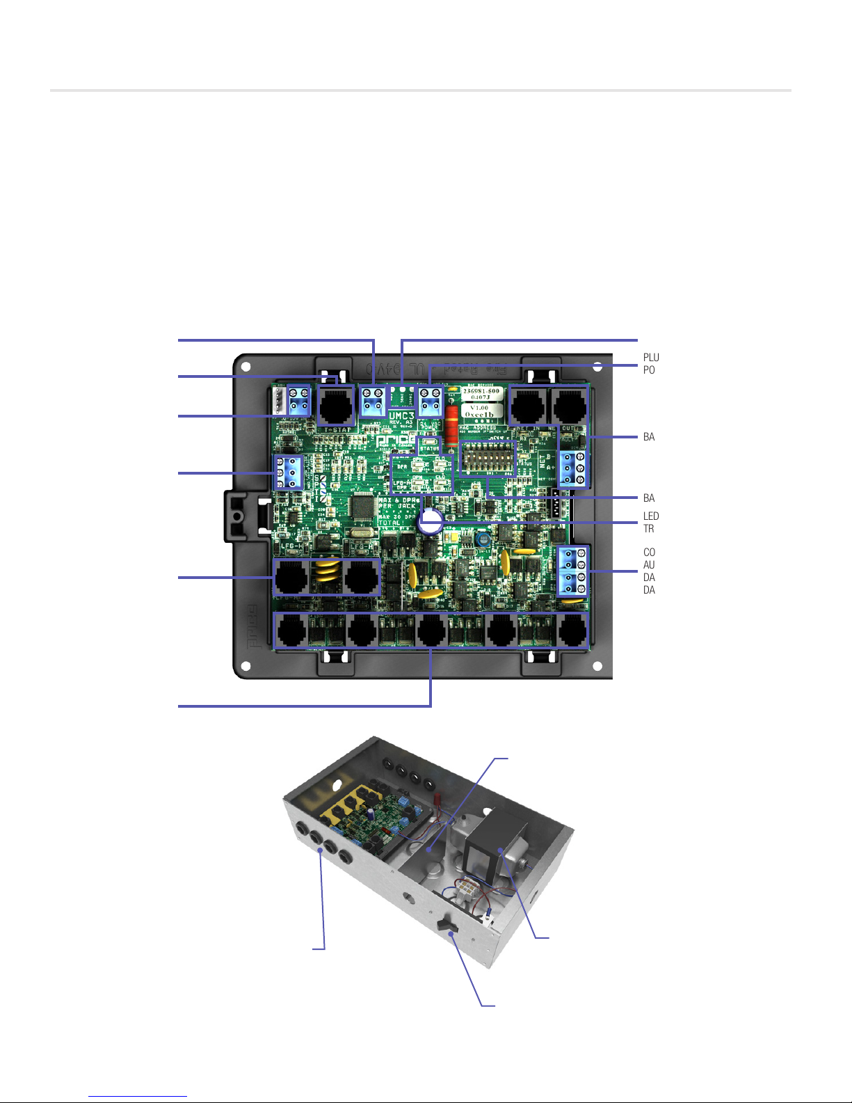
• Thermostat port - For RJ-45 connection to thermostat from
the UMC3 controller.
• Native BACnet MS/TP communication – Connect using RJ-
45 cable, or use discrete twisted-pair wire to terminal block.
Available speeds: 9600, 19200, 38400, 76800 (default).
• LED Indication – For ease of troubleshooting – displays
status, damper directions, BACnet status, and output fault.
• Pluggable terminal blocks – For easy installation.
• High-Voltage disconnect switch.
• 96 VA multi-tap transformer with circuit breaker.
• Metal safety guard separating high and low voltage areas.
• 8 grommeted openings for modular cable connections.
• Temperature sensor input (for monitoring).
• Disconnect switch.
• Pluggable 24VAC power terminal.
Operation
The UMC3 controller is an advanced and fully configurable
underfloor ModuFlex cooling controller. It is typically interfaced
with one of four Price Thermostats to determine room load and
allow for setup functions. With a variety of output configurations,
the UMC3 can control up to 30 underfloor dampers, as well as
auxiliary equipment using its auxiliary 24VAC binary outputs, and
analog 0-10V outputs.
Upon an increase in space temperature the controller regulates the
dampers open to increase the flow of cool air. On an increase
of space temperature greater than the proportional band,
the dampers’ positions are maintained at their pre-selected
maximum setting.
On a decrease in space temperature the controller regulates the
dampers closed to decrease the flow of cool air. If connected to
LFGH floor grills with integrated damper and reheat, the UMC3
will energize or modulate the heat proportionally to the room
demand. If the space temperature decreases to less than the
proportional band, the dampers’ positions are maintained at
their pre-selected minimum setting.
The UMC3 can also be configured to accept 0-10V input signals
from a BAS system or third party thermostat for room load
calculations, instead of data from the thermostat.
The UMC3 can be used as a stand alone unit, or can be
interfaced into a BAS with the MS/TP BACnet network.
The UMC3 offers four thermostat options that provide a range
of control from room temperature sensing, all the way to motion
sensing. With the use of the LCD Thermostat, balancing and
system setup can be achieved. Further, with the use of the LCD
Thermostat with Motion, the UMC3 can be used as a motion-
occupied zone and lighting controller. The LCD Thermostat with
Motion offers different levels of sensitivity and still performs all
the functions of the regular LCD Thermostat.

5
priceindustries.com |UNDERFLOOR MODUFLEX CONTROLLER - Manual
UNDERFLOOR MODUFLEX CONTROLLER
INSTALLATION & MOUNTING INSTRUCTIONS
Installation
1. Place the UMC3 in the underfloor plenum in the center of
the controlled zone using a 35 ft. cable.
2. Supply power and ground to terminal per wiring diagram.
NOTE: This task must be completed by a certified and
licensed electrician.
3. Connect underfloor dampers using modular cables
supplied with dampers. Follow these general rules:
A. Connect no more than 30 dampers total
B. Daisy chain up to 6 dampers per output – no more
C. Do not connect standard dampers (with RJ-12 plug) to
LFGH outputs (which use RJ-45 plug)
D. LFGH dampers (up to 12) count towards the maximum
of 30 dampers per controller
4. Run thermostat wire to thermostat, and plug into “T-Stat”
port on the UMC3. (For thermostat installation reference
the Installation & Mounting Instructions Thermostat
Installation section.)
5. Connect BACnet network (if used). For more detailed
information on networking with UMC3 reference the
Display Navigation Address Menu section.
6. Flip the UMC3’s power switch to the ON position.
Price Flow Response Chart
HCCO Response Cooling
Min
Cooling
Flows
Heating
Min
Heating
Flows
Neutral Supply
Air Flow
PI = Cooling Supply air = Cold D L
PI = Heating Supply air = Cold D L
PI = Neutral Supply air = Cold D L
PI = Cooling Supply air = Hot D L
PI = Heating Supply air = Hot D L
PI = Neutral Supply air = Hot D L
PI = Cooling Supply air = Neutral D L
PI = Heating Supply air = Neutral D L
PI = Neutral Supply air = Neutral D L
“D” indicates the target of the regular dampers and “L” represents the target of the LFGH dampers (with integrated reheat)
NOTE 1: By default the UMC3 is shipped configured for cold supply air only. This can be changed to enable HCCO with
thermistor probe (however this will almost never be the case).
NOTE 2 : PI = Proportional Integral = room load (either cooling/neutral/heating)
Above is a flow response chart for the UMC3, showing the demand, duct air condition, and the controller’s output.
E.g.: PI = Cooling, Supply Air = Cold, Output = Cooling Flows. This indicates that the room demand is in cooling, the supply air is cold,
and the controller would modulate both the regular dampers and the LFGH dampers between the Cool Min and Cool Max values.
Use the above table to determine what airflows are being chased in certain modes. Example: If UMC3 is trying to heat the room (PI = Heating)
and cool air is being supplied (Duct Air = Cold) it will chase its heating min flow.
TECH TIP

6UNDERFLOOR MODUFLEX CONTROLLER - Manual |priceindustries.com
UNDERFLOOR MODUFLEX CONTROLLER
INSTALLATION & MOUNTING INSTRUCTIONS
Input/Output Description
24VAC Binary Outputs Description
BO – DPR OPN Plenum damper open. Used for floating point actuators.
BO – DPR CLO Plenum damper closed. Used for floating point actuators.
BO – AUX Aux binary output available.
Analog Outputs
AO – Heat Signal sent to LFGH diffusers (0-10VDC)
AO – Aux Aux analog output available (0-10VDC)
Analog 0-10VDC Inputs
AI4 – Cooling
Can be configured (along with AI5) to control the UMC3 from a third party
thermostat. In this configuration, AI4 is the 0-10VDC cooling load input.
Can also be used for simple voltage monitoring when analog
inputs are not configured as control source.
AI5 – Heating
Can be configured (along with AI4) to control the UMC3 from a third party
thermostat. In this configuration, AI5 is the 0-10VDC cooling load input.
Can also be used for simple voltage monitoring when analog
inputs are not configured as control source.
Additional Inputs
AI1 – 5VDC Sensor Typically used for voltage monitoring over BACnet network.
THERM
Analog Input for temperature probe hookup with 10k Type J Thermistor.
Typically used for temperature monitoring over BACnet network.
Can also be configured for heat/cool changeover if required.

7
priceindustries.com |UNDERFLOOR MODUFLEX CONTROLLER - Manual
UNDERFLOOR MODUFLEX CONTROLLER
INSTALLATION & MOUNTING INSTRUCTIONS
Wiring
Below is an example of a typical UMC3 layout.

8UNDERFLOOR MODUFLEX CONTROLLER - Manual |priceindustries.com
UNDERFLOOR MODUFLEX CONTROLLER
INSTALLATION & MOUNTING INSTRUCTIONS
Thermostat Installation
General Description
The UMC3 Thermostats are all physically the same size and
mounting instructions will be typical.
Location
1. The Third-Generation Underfloor ModuFlex Controller
(UMC3) Thermostats must be mounted to a wall and wired
to the controller via the supplied plenum rated 35 ft. CAT-5
cable. This cable plugs into the thermostat and the UMC3
controller with the ease of RJ-45 connections.
NOTE: The cable run can be extended to 70 ft. using a
Price cable coupler and additional 35 ft. cable.
2. Mount the required thermostat in a place that is
convenient for the end user, but the following should be
taken into consideration:
• Do not mount a thermostat in direct sunlight i.e. across
from a window where heat can alter the temperature
reading.
• Should not be installed on an outside wall.
• Keep away from hot equipment like computers,
monitors and heaters etc.
• Ensure nothing will restrict vertical air circulation to the
thermostat. (Do Not Cover)
• Ensure wall is NOT pressurized! Hot/Cold air from a
pressurized wall will blow directly onto the thermostat’s
temperature sensor causing inaccurate readings.
Installation
1. The back plate on each thermostat is removable and can
be mounted to a standard electrical box or directly to
drywall using anchors supplied by others.
2. Run the CAT-5 cable through the center hole in the plate
and connect the cable to the thermostat. Then, secure the
thermostat onto the wall plate by inserting the top portion
of the thermostat first, then snapping the bottom half in.
3. All thermostats will come equipped with a 0.050 in. Allen
Key for the set screw at the bottom.
Careful thermostat installation will reduce field issues! Do
not twist or kink the blue CAT-5 thermostat cable. Damaged
cables are difficult to troubleshoot!
Thermostat cable product code: C25 Cable
TECH TIP
www.priceelectronics.ca
Page 6 of 24
Thermostat Installation
Location
1. The Price Analog Controller (PAC) Thermostats mu st be mounted to a wall and wired to the PAC
controller. The connecting cable screws into the thermostat and the PAC controller with the
supplied terminal blocks. Note: the cable run can beup to 70 ft.
2. Mount the required thermostat in a place that is convenient for the end user, but the following
should be taken into consideration:
•Do not mount a thermostat in direct sunlight i.e. across from a window where heat can
alter the temperature reading.
•Should not be installed on an outside wall .
•Keep away from hot equipment like computers, monitors and heaters etc.
•Ensure nothing will restrict vertical air circulationto the thermostat. (Do Not Cover)
•***Ensure wall is NOT pressurized! Hot/cold air fr om a pressurized wall will direct
blow onto the thermostat’s temperature sensor causi ng ‘bad’ readings. ***
Installation
1. The back plate on each thermostat is removable and can be mounted to a standard electrical box
or directly to drywall using anchors supplied by ot hers.
2. Run the cable through the center hole in the plate. Connect the cable to the thermostat, and then
secure the thermostat onto the wall plate inserting the top portion of the thermostat first, and then
snapping the bottom half in.
3. The thermostat will come equipped with a 0.050” Allen key for the set screw at the bottom.
How to use the Dial Thermostat
•The Dial Thermostat is powered from the PACcontroller.
•Measures room temperature and features a dial adju stment and an occupancy
button.
•Temperature Setpoint limits can be adjusted throug h free setup software using
the Price LINKER, or through an LCD Setup Stat.
•Simply use the adjustable dial for temperature adj ustment.
•Occupancy button can be used to override the systemduring unoccupied
times. Default setting is 4hrs.
T
ECH TIP: Careful thermostat installation will reduce field
issues! Do not twist or kink the thermostat cable.
Damaged cables are difficult to troubleshoot!
1.25" (32MM)
WALL FASTENERS
BY OTHERS
35 FOOT PLENUM RATED NETC35 CABLE INCLUDED
SURFACE MOUNT DETAIL

9
priceindustries.com |UNDERFLOOR MODUFLEX CONTROLLER - Manual
UNDERFLOOR MODUFLEX CONTROLLER
INSTALLATION & MOUNTING INSTRUCTIONS
How to use Thermostats
Room Sensor Thermostat
• Measures room temperature.
• Setpoint can be adjusted from a hidden dial on the back of the thermostat using a
small flat-head screw driver.
• Setpoint limits can be adjusted through free setup software using the Price
LINKER, or through a BACnet system.
• Eliminated problem of unauthorized tampering with the thermostat.
• Occupancy button can be used to override the system during unoccupied times.
Default setting is 4 hours.
Dial & Wireless Thermostat
Dial Thermostat
• Measures room temperature and features a dial adjustment and an occupancy button.
• Temperature Setpoint limits can be adjusted through free setup software using the
Price LINKER, or through a BACnet system.
• Simply use the adjustable dial for temperature adjustment.
• Occupancy button can be used to override the system during unoccupied times.
Default setting is 4 hours.
• LED light indicates what mode the thermostat is in. One blink is cooling mode,
two blinks is heating mode, three blinks is neutral.
Wireless Thermostat
• Functionally identical to the Dial Thermostat.
• Requires wireless receiver, see Wireless Thermostat manual for details on
installation.
LCD Thermostat
• Measures room temperature and features an LCD screen with push button day
Setpoint adjustment.
• Temperature Setpoint limits are set through the thermostat setup menus, free
setup software using the Price LINKER, or through a BACnet system.
• Balancing and additional setup functions also available through the menus.
LCD Thermostat with Motion Sensor
• This model measures room temperature, features an LCD screen with day
Setpoint adjustment, and motion sensor with lighting control.
• Temperature Setpoint limits are set through the thermostat setup menus, free
setup software using the Price LINKER, or through a BACnet system.
• Balancing and additional setup functions are also available through the menus.
• This model is equipped with a motion sensor to determine occupancy of the
space. This sensor can also be used to control lighting.
NOTE: All Price Thermostats are powered via the RJ-45 connection to the controller
ROOM SENSOR THERMOSTAT
DIAL & WIRELESS THERMOSTAT
LCD THERMOSTAT
LCD THERMOSTAT W/ SENSOR

10 UNDERFLOOR MODUFLEX CONTROLLER - Manual |priceindustries.com
UNDERFLOOR MODUFLEX CONTROLLER
DISPLAY NAVIGATION
Initial Startup
(LCD & Motion Thermostat only)
When the LCD thermostat is powered from the UMC3, it will display the following information:
Changing the Setpoint – LCD & Motion Thermostat only
Day Setpoint Adjustment. Increase and decrease push buttons for Day Setpoint adjustment
PRICE ELECTRONICS Start-up screen
LCD THERMOSTAT
STANDARD MODEL Standard/Motion Model
LCD THERMOSTAT
VERSION X.XX Displays firmware version of thermostat
LOADING:
INITIALIZING Loading parameters
UMC3
VERSION X.XX Controller type and controller firmware version
SEQUENCE
XXXX
Displays sequence programmed into stat
NOTE: a sequence number of 0 means the stat has NOT been calibrated
MAC ADDRESS
XXX Displays current MAC Address
DEVICE INST.
XXXXXXX Displays current Device Instance
ROOM TEMP.
75.0°F (For example)
DAY SETPOINT
75.0°F
DAY SETPOINT
SAVING...

11
priceindustries.com |UNDERFLOOR MODUFLEX CONTROLLER - Manual
UNDERFLOOR MODUFLEX CONTROLLER
DISPLAY NAVIGATION
Service Menu
(LCD & Motion Thermostat only)
The Service menu allows the balancer/installer to access to the controller setup to change settings.
For example setting flows, heating outputs, etc.
Hold ‘Enter Menu’ button for 5 seconds. Display will show ‘Passcode:’
Use ‘Up’ and ‘Down’ buttons to enter this passcode: Down - Up - Up - Down.
BALANCING • Allows you to force damper open/close/min/max
VVT • Allows you to set limits (%) in VVT mode
SETPOINT • Setup of Setpoint limits (day minimum/maximum)
• °F / °C selection
INPUT • Shows thermistor reading
• Allows setting of HCCO if desired
OUTPUT • Allows setup of auxiliary binary and analog outputs
• Allows setup of room light output (motion stat only)
ADDRESS • Allows setup of BACnet addresses
• MAC address, Device Instance Baud Rate
STAT SETUP • Allows setup of LCD back lighting, sounds, motion sensor
• Adjustment of HVAC and room lighting timeouts
PRESS MENU
TO EXIT
• This will exit the Service Menu if you press the Enter/Menu button
• NOTE: Service menu will automatically time out after 20 seconds

12 UNDERFLOOR MODUFLEX CONTROLLER - Manual |priceindustries.com
UNDERFLOOR MODUFLEX CONTROLLER
DISPLAY NAVIGATION
Balancing Menu
Scroll through with the ‘Up’ and ‘Down’ buttons. Press ‘Enter/Menu’ button to apply your changes. ‘...Saving...’ will display as
your changes are applied.
BALANCING
PRESS MENU
TO EXIT
DPR. OVERRIDE
DISABLED DPR. OVERIDE
GOTO COOL MIN Cool Min
Regular and LFGH dampers go to their Cool Minimum positions
DPR. OVERIDE
GOTO COOL MAX
Cool Max
Regular and LFGH dampers go to their Cool Maximum positions
DPR. OVERIDE
GOTO HEAT MIN
Heat Min
Regular and LFGH dampers go to their Heat Minimum positions
DPR. OVERIDE
GOTO HEAT MAX
Heat Max
Regular and LFGH dampers go to their Heat Maximum positions
DPR. OVERIDE
GOTO NEUTRAL
Neutral Flow
Regular and LFGH dampers go to their Neutral Supply Air positions
DPR. OVERIDE
GOTO FULL OPN
Full Open
Force all dampers and LFGH full open
DPR. OVERIDE
GOTO FULL CLO
Full Close
Force all dampers and LFGH closed
POSITION
TARGET
• Display shows current target and position
• Controller will remain in this mode until user exits the
menu

13
priceindustries.com |UNDERFLOOR MODUFLEX CONTROLLER - Manual
UNDERFLOOR MODUFLEX CONTROLLER
DISPLAY NAVIGATION
VVT Menu
(Pressure Dependent Damper Ranges)
Scroll through with the ‘Up’ and ‘Down’ buttons. Press ‘Enter/Menu’ button to apply your changes. ‘Saving...’ will display as your
changes are applied.
VVT
PRESS MENU
TO EXIT
DPR. RUNTIME
90 SEC.
Damper Runtime
• Damper runtime (time to drive through entire damper range)
• Range: 0-600 seconds Default: 90 seconds
LFGH COOL MIN
0%
LFGH Cool Min Position
• LFGH Cool Minimum Position in %
• Range: 0-100% Default: 0%
LFGH COOL MAX
100%
LFGH Cool Max Position
• LFGH Cool Maximum Position in %
• Range: 0-100% Default: 100%
LFGH HEAT MIN
0%
LFGH Heat Min Position
• LFGH Heat Minimum Position in %
• Range: 0-100% Default: Depends on sequence
LFGH HEAT MAX
100%
LFGH Heat Max Position
• LFGH Heat Maximum Position in %
• Range: 0-100% Default: Depends on sequence
LFGH NEUTRAL
0%
LFGH Neutral Supply Air position (not normally used)
• LFGH position (in %) when Neutral supply air is present
• Range: 0-100% Default: 50%
LFGH RUNTIME
90 SEC
LFGH Neutral Supply Air position (not normally used)
• LFGH Damper runtime (time to drive through entire damper range)
• Range: 0-600 seconds Default: 90 seconds
DPR. COOL MIN
0%
Damper Cool Min Position
• Cool Minimum position in %
• Range: 0-100% Default: 0%
DPR. COOL MAX
100%
Damper Cool Max Position
• Cool Maximum position in %
• Range: 0-100% Default: 100%
DPR. HEAT MIN
0%
Damper Heat Min Position
• Heat minimum position in %
• Range 0-100% Default: 0%
DPR. HEAT MAX
100%
Damper Heat Max Position
• Heat Maximum Position in %
• Range 0-100% Default: 100%
DPR. NEUTRAL
0%
Damper Neutral Supply Air position (not normally used)
• Damper position (in %) when Neutral Supply Air is present
• Range 0-100% Default: 0%
UNOCC DPR POS
33%
Unoccupied Damper Position
• Unoccupied (Night Setback) Damper position in %
• Range: 0-100% Default: 33%

14 UNDERFLOOR MODUFLEX CONTROLLER - Manual |priceindustries.com
UNDERFLOOR MODUFLEX CONTROLLER
DISPLAY NAVIGATION
SET LO LIMIT
65.0°F
Day Setpoint Low Limit
• This is the lowest Setpoint allowed
• Range: 10.0°F – 100.0°F Default: 65.0°F
SET HI LIMIT
80.0°F
Day Setpoint High Limit
• This is the lowest Setpoint allowed
• Range: 10.0°F – 100.0°F Default: 80.0°F
TEMP. UNITS
FEHRENHEIT
Termperature Units
• Fahrenheit or Celsius
• Default: °F
NIGHT HEAT SET
62.0°F
Night Heat Setpoint
• UMC3 will maintain this heating Setpoint when unoccupied
• Range: 10.0°F – 100.0°F Default: 62.0°F
NIGHT COOL SET
83.0°F
Night Cool Setpoint
• UMC3 will maintain this cooling Setpoint when unoccupied
• Range: 10.0°F – 100.0°F Default: 83.0°F
PRO. BAND
2.0°F
Proportional Band
• The Proportional Band is the temperature range through which the controller calculates a
0-100% load
• Range: 0.5°F – 25.0°F Default: 2°F
DAY DIFF.
1.0°F
Day Differential
• This is the maximum allowed “error” on either side of the room Setpoint before the controller
will enter its heating or cooling proportional bands
• Range: 0.5°F – 25.0°F Default: 1.0°F
CONTROL FROM
THERMOSTAT
Control Source
• Thermostat: Controller uses thermostat temperature and Setpoint to determine room load and
control
• Analog Input: Controller uses 0-10VDC inputs to determine room load and control. Use this
control source type for a 0-10VDC signal by others.
PRESS MENU
TO EXIT
SETPOINT
Setpoint Menu
(Setpoint Limits and Temperature Units)
Scroll through with the ‘Up’ and ‘Down’ buttons. Press ‘Enter/Menu’ button to apply your changes. ‘Saving...’ will display as your
changes are applied.

15
priceindustries.com |UNDERFLOOR MODUFLEX CONTROLLER - Manual
UNDERFLOOR MODUFLEX CONTROLLER
DISPLAY NAVIGATION
SUPPLY AIR TEMP
50.0°F
Supply Air Temperature (S.A.T.) readout
• Shows current thermistor probe reading
• Range: -59.0°F – 300.0°F
• “No Probe” means no sensor is connected
NEUTRAL MODE
FORCE COOL
Neutral Mode
Controls Supply Air calculations by the UMC3
NOTE: Default mode is “Force Cool”. This will be used 99.9% of the time.
• Neutral Mode: Dynamic
- When Supply Air Temperature (as measured on thermistor input) is below room temp, it is
considered cold
- When Supply Air Temperature (SAT) is above room temp, it is considered hot
- NOTE: There is a 2 degree differential on either side of the current room temperature
which would equate to Neutral Supply Air if the SAT fell within this range.
• Neutral Mode: Conventional
- Uses hot/cold switch points which are hard set below
- Not recommended
• Neutral Mode: Force Cool
- UMC3 Default
- Controller assumes cold supply air at all times (despite any reading of T1 Thermistor input)
- This is useful by allowing the T1 thermistor input to be used for monitoring only
• Neutral Mode: Force Heat
- Control assumes hot supply air at all times
- Not recommended
HOT SWITCH
0.0°F
Hot Switch - Only active/visible when Neutral mode = Conventional
• Only active/visible when Neutral mode = Conventional
• UMC3 will consider the supply air warm if at the hot switch temp or above
• Default: 0.0°F – UMC3 defaults to Cool supply air at all times
COLD SWITCH
0.0°F
Cold Switch - Only active/visible when Neutral mode = enabled
• Only active/visible when Neutral mode = Enabled
• UMC3 will consider the supply air cold if at the cold switch temp or below
• Default: 0.0°F – UMC3 defaults to Cool supply air at all times
RM. TMP. OFFSET
0.0°F
SAT OFFSET
0.0°F
PRESS MENU
TO EXIT
INPUT
Input Menu
(Supply Air Temp and Neutral Mode)
Scroll through with the ‘Up’ and ‘Down’ buttons. Press ‘Enter Menu’ button to apply your changes. ‘Saving...’ will display as your
changes are applied.

16 UNDERFLOOR MODUFLEX CONTROLLER - Manual |priceindustries.com
UNDERFLOOR MODUFLEX CONTROLLER
DISPLAY NAVIGATION
OUTPUT
OUTPUT
ANALOGS
OUTPUT
AUX BINARY
PRESS MENU
TO EXIT
Output Menu - Aux Binary
(Setup of Auxiliary Binary Output)
Scroll through with the ‘Up’ and ‘Down’ buttons. Press ‘Enter Menu’ button to apply your changes. ‘Saving...’ will display as your
changes are applied.
USED AS
HEAT OUTPUT
(Default) Output energized when the room demand is heating and the heat load is at or above
trip point (below)
USED AS
COOL OUTPUT Output energized when the room demand is cooling and the cool load is at or above trip point
USED AS
HEAT AND COOL Output energized when the room demand is heating or cooling and load is above trip point
USED AS
DEADBAND OUTPUT Output energized with room is satisfied
USED AS
ROOM LIGHTS When using Motion Thermostat, output controls room lights
USED AS
FORCE OFF Output de-energized at all times
USED AS
FORCE ON Output energized at all times
TRIP POINT
5%
• Room load at which output is energized. (Heat, Cool, and Heat&Cool modes)
• Range: 1-100%
• Default: 5%
PRESS MENU
TO EXIT

17
priceindustries.com |UNDERFLOOR MODUFLEX CONTROLLER - Manual
UNDERFLOOR MODUFLEX CONTROLLER
DISPLAY NAVIGATION
ANA. HEAT MIN
0.0 VDC
Analog Heat Min Voltage
• Outputs this voltage on Analog Heat pin (and LFGH outputs) when there is a minimum call for heating
• Default: 0.0VDC
ANA. HEAT MAX
10.0 VDC
Analog Heat Max Voltage
• Outputs this voltage on Analog Heat pin (and LFGH outputs) when there is a maximum call for heating
• Default: 10.0VDC
ANA. HEAT IDLE
0.0 VDC
Analog Heat Idle Voltage
• Outputs this voltage on Analog Heat pin (and LFGH outputs) when there is no call for heating
• Default: 0.0VDC
AUX COOL MIN
0.0 VDC
Auxillary Cool Min Voltage
• Outputs this voltage on Auxiliary Analog pin when there is a minimum call for cooling
• Default: 0.0VDC
AUX COOL MAX
10.0 VDC
Auxillary Cool Max Voltage
• Outputs this voltage on Auxiliary Analog pin when there is a maximum call for cooling
• Default: 10.0VDC
AUX HEAT MIN
0.0 VDC
Auxillary Heat Min Voltage
• Outputs this voltage on Auxiliary Analog pin when there is a minimum call for heating
• Default: 0.0VDC
AUX HEAT MAX
0.0 VDC
Auxillary Heat Max Voltage
• Outputs this voltage on Heat Analog pin when there is a maximum call for heating
• Default: 0.0VDC
AUX DEADBAND
0.0 VDC
Auxillary Deadband Voltage
• Outputs this voltage on Auxiliary Analog pin when there is no call for heating or cooling (deadband)
• Default: 0.0VDC
PRESS MENU
TO EXIT
OUTPUT
OUTPUT
ANALOGS
PRESS MENU
TO EXIT
OUTPUT
AUX BINARY
Output Menu - Analog Outputs
(Setup of Analog Outputs)
Scroll through with the ‘Up’ and ‘Down’ buttons. Press ‘Enter Menu’ button to apply your changes. ‘Saving...’ will display as your
changes are applied.

18 UNDERFLOOR MODUFLEX CONTROLLER - Manual |priceindustries.com
UNDERFLOOR MODUFLEX CONTROLLER
DISPLAY NAVIGATION
Stat Setup Menu
(Stat Options)
Scroll through with the ‘Up’ and ‘Down’ buttons. Press ‘Enter/Menu’ button to apply your changes. ‘Saving...’ will display as your
changes are applied.
OCCUPANCY
ON - AIRFLOW
Occupancy
• Show current occupancy source
• ON from VVT (always on), ON from Airflow, ON from Contact, ON from Motion Sensor
MOTION ENABLE
OFF
Motion Enable (Motion sensor STAT only)
• Off – motion sensor disabled – Default for regular LCD Thermostat
• On – motion sensor enabled (only enabled if you have a motion stat)
• Only visible with motion stat
MOTION SENSITIVITY
Motion Sensitivity (Motion sensor STAT only)
• Sets the sensitivity of the motion sensor
• 1 – least sensitive
• 9 – most sensitive
• 5 – DEFAULT
• Only visible when motion is enabled
MOTION TEST
OFF
Motion Test (Motion sensor STAT only)
• Motion Thermostat will beep each time motion is sensed
• This is useful for adjusting the sensitivity value & testing
HVAC TIMEOUT
240 MIN.
HVAC Timeout
• UMC3 will go into unoccupied after no motion is detected and this timer expires
• Default: 240 minutes
LIGHTS TIMEOUT
60 MIN.
Lights Timeout (Use room light output to select lighting signal)
• UMC3 will turn off lighting output after no motion is detected and this timer expires
• Default: 60 minutes
LCD BACKLIGHT
ALWAYS ON
LCD Backlight
• Always on (Default)
• Always off
• Button push – lights up on button press
SOUND OPTIONS
LIMITS ONLY
Sound Options
• User Sounds – stat will beep when user tries to exceed a limit – Default
• All off – beeper disabled
• All on – stat will beep when user tries to exceed a limit or stat loses communication with the
controller (for testing use only) – not recommended
PRESS MENU
TO EXIT
STAT SETUP
Table of contents
Other Price Controllers manuals
Popular Controllers manuals by other brands

National Instruments
National Instruments SCXI NI 1357 installation guide

Paia
Paia 8700 Assembly and using manual

Regulus
Regulus uREG user manual

Johnson Controls
Johnson Controls VA-7010 Series Product/Technical Bulletin

TREND
TREND LonMark IQL13+ Series installation instructions

Pioneer
Pioneer DDJ-RB Service manual

Power Products
Power Products SOLAR BOOST 3048 Installation and operation

PMA
PMA Relay S Series user manual

GYS
GYS STARTPACK 12.24 CI instructions

United Process Controls
United Process Controls PROTHERM 50 operating manual

SMC Networks
SMC Networks LEF Series Maintenance manual

Beijer Electronics
Beijer Electronics BFI-P2/E3 quick start guide