Price PCV Series User manual

v400 –Issue Date: 12/23/20
© 2021 Price Industries Limited. All rights reserved.
MANUAL – INSTALLATION + SERVICE
Pressure Control Valve
PCV Series

Having difficulty installing this product? Price is here to help.
Application Support
204.654.5613
priceindustries.com/controls
SUPPORT
DAMPER ACTUATOR
Product Overview
General .........................................................................1
Pressure Control Methods.............................................2
PCV Sizing ....................................................................3
Installation
Installing the PCV Unit...................................................4
LCD Set-up Tool............................................................4
Mounting Instructions....................................................5
Balancing
Balancing Instructions ...................................................6
Display Navigation
Info Menu......................................................................7
Service Menu ...............................................................8
Application Menu ..........................................................9
Setpoint Menu............................................................. 10
Discharge Air Temperature Menu.................................11
Input Menu..................................................................12
Output Menu – Heat....................................................13
BACnet Menu .............................................................14
Stat Setup Menu ......................................................... 15
P/C Setup Menu .........................................................16
BACnet Networking
BACnet Wiring ...........................................................17
BACnet Networking And Setup ................................... 18
Setting The Device Instance ........................................19
BACnet Service Menu .................................................21
Maintenance
Troubleshooting...........................................................23
Hardware Specifications.............................................. 24
PRESSURE CONTROL VALVE
TABLE OF CONTENTS

General
PCV - Pressure Control Valve
The Pressure Control Valve (PCV) is a device that controls duct static pressure. The PCV can be setup for bypass control or for
downstream throttling control.
• Bypass control maintains a constant supply duct pressure
by redirecting the air that's not required to go into the
zones at that time from the supply duct to the return
duct. In the bypass arrangment as static pressure in the
supply duct begins to rise, the damper opens to alleviate
the excess pressure to the return. Returns can be open
plenum, or ducted.
• Downstream throttling control is typically used to control
static pressure in a branch or portion of a system where
a lower static pressure is desired with respect to the rest
of the system. In these arrangements, there is already
a bypass or VFD maintaining the overall system static.
The PCV maintains the static pressure in the branch it's
controlling by holding back air that is not required to go into
the zones it's serving. As the static pressure begins to rise,
the damper begins to close to hold back excess pressure
where the system bypass or VFD would take care of it.
PCV CONTROLLER FEATURES
PORT FOR
LCD T-STAT
CONNECTION
(SETUP ONLY)
SERVICE PORT FOR
PRICE LINKER
DAMPER ACTUATOR
PLUGGABLE 24 VAC POWER
TERMINAL OR RJ-12 POWER CONNECTION
REQUIRED
DIFFERENTIAL
PRESSURE
TRANSDUCER
OPTIONAL BACNET
EXPANSION MODULE
1
PRESSURE CONTROL VALVE
PRODUCT OVERVIEW
priceindustries.com |PRESSURE CONTROL VALVE - Manual

2
PRESSURE CONTROL VALVE
PRODUCT OVERVIEW
PRESSURE CONTROL VALVE - Manual |priceindustries.com
Pressure Control Methods
Open Return Bypass Method
In the case of an “open return” system,
the duct work is ducted so that the
return side of the PCV (pressure
controller) is open to the plenum. (See
Figure 1.1) This means that the air will
get bypassed through the PCV and
then into the ceiling plenum. This type
of system is quite common and easier
to duct.
Ducted Return Bypass Method
In the case of a ducted return system,
the duct work would be ducted so that
the return side of the PCV (pressure
controller) is ducted back to the unit,
either the rooftop unit or the air handler.
(See Figure 1.2) This means that the air
will get bypassed through the PCV and
then back into the unit. One thing to
consider in this type of ducting method
is that this could cause the coils in the
air handling unit to freeze up if too much
air is returned at a very low temperature
or similarily in heating mode too much
warm return air could trip the heat high
temp limits. The air handler should
be fitted with a low temp cutout for
cases like this to prevent the coils from
freezing.
Return Supply
Pressure Control Valve
P
Static Pressure Tubing
Static Pressure Sensor
P
FIGURE 1.1 - OPEN RETURN BYPASS METHOD (SEQUENCE 1550)
Return
Supply
Pressure Control Valve
P
Static Pressure Tubing
Static Pressure Sensor
P
FIGURE 1.2 - DUCTED RETURN BYPASS METHOD (SEQUENCE 1550)

because of VAV diffusers modulating closed, the PCV damper begins to close to limit airflow into the downstream duct. When the
VAV diffusers begin to open to more allow airflow out of the duct and into the occupied space, the pressure in the duct will begin
to drop, and the PCV damper will begin to open to maintain a constant duct pressure to feed the diffusers.
NOTE: This method can only be used in conjuction with a system bypass PCV or VFD on RTU controlling the duct static for the
whole system; throttling PCV applications are for isolating low pressure branches on a higher pressure system only
Pressure Control Methods
Throttling Method
Throttling applications are used to
isolate low pressure branches of
ductwork from the rest of a system
operating at a higher duct static
pressure. Usually these branches serve
VAV diffusers which require a much
lower inlet static pressure compared
to traditional VAV terminal units due to
the noise higher than recommended
pressures due to the noise generated
by higher than reccomended inlet static
pressure.
Throttling applications work by using the
PCV to hold back excess pressure from
the system to the low pressure branch it
is isolating. This means that as pressure
PCV Sizing
To size PCVs correctly, they should be able to bypass 2/3's of the
system design airflow at 1000 - 1500 FPM.
This means that a system with 6000 design CFM would need a PCV
capable of bypassing 4000 CFM which would require a damper whose
area is 2.67 to 4 square feet. In square inches, this is 384 to 576 (there
are 144 square inches in 1 square foot). Based on the area calculated,
a rectangular damper anywhere from 24 x 16 (384 in sq - higher side
of velocity range) to 28 x 20 (560 in sq - lower side of velocity range -
recommended) can be used.
PCV Damper Area in² = * 144
NOTE: We recommend calculating the damper size required with the
low velocity first and if the damper size doesn't fit within the physical
constraints of the job, only then increasing the velocity up to a maximum
of 1500 FPM
3
PRESSURE CONTROL VALVE
PRODUCT OVERVIEW
priceindustries.com |PRESSURE CONTROL VALVE - Manual
Return Supply
Pressure Control Valve
P
Static Pressure Tubing
Static Pressure Sensor
P
FIGURE 1.3 - THROTTLING METHOD (SEQUENCE 1551)

4
PRESSURE CONTROL VALVE
INSTALLATION
PRESSURE CONTROL VALVE - Manual |priceindustries.com
Installing the PCV Unit
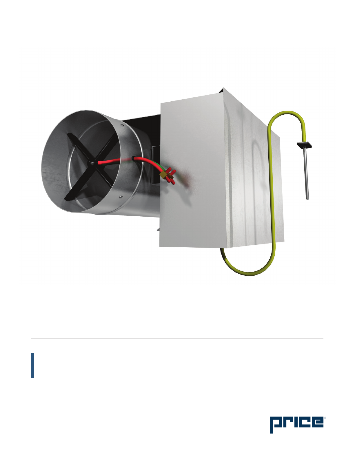
1. The PCV consists of a damper (often a Price model RDV)
and a PIC controller that is programmed for pressure
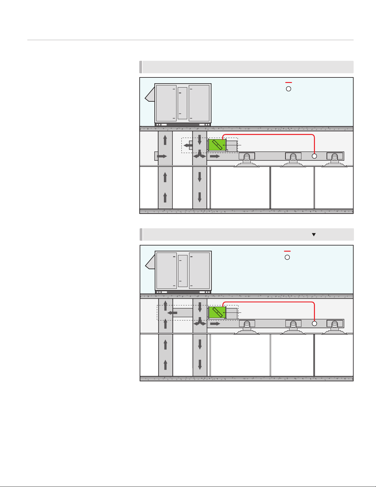
control. The PCV should be installed on the supply duct
running off of the rooftop unit. For bypass applications, the
PCV will go in between the supply and return duct (return
may be open and return directly to the ceiling plenum).
For downstream throttling applications, the PCV should
be installed directly in the supply duct, before the first VAV
box or VAV diffuser in the branch being served.
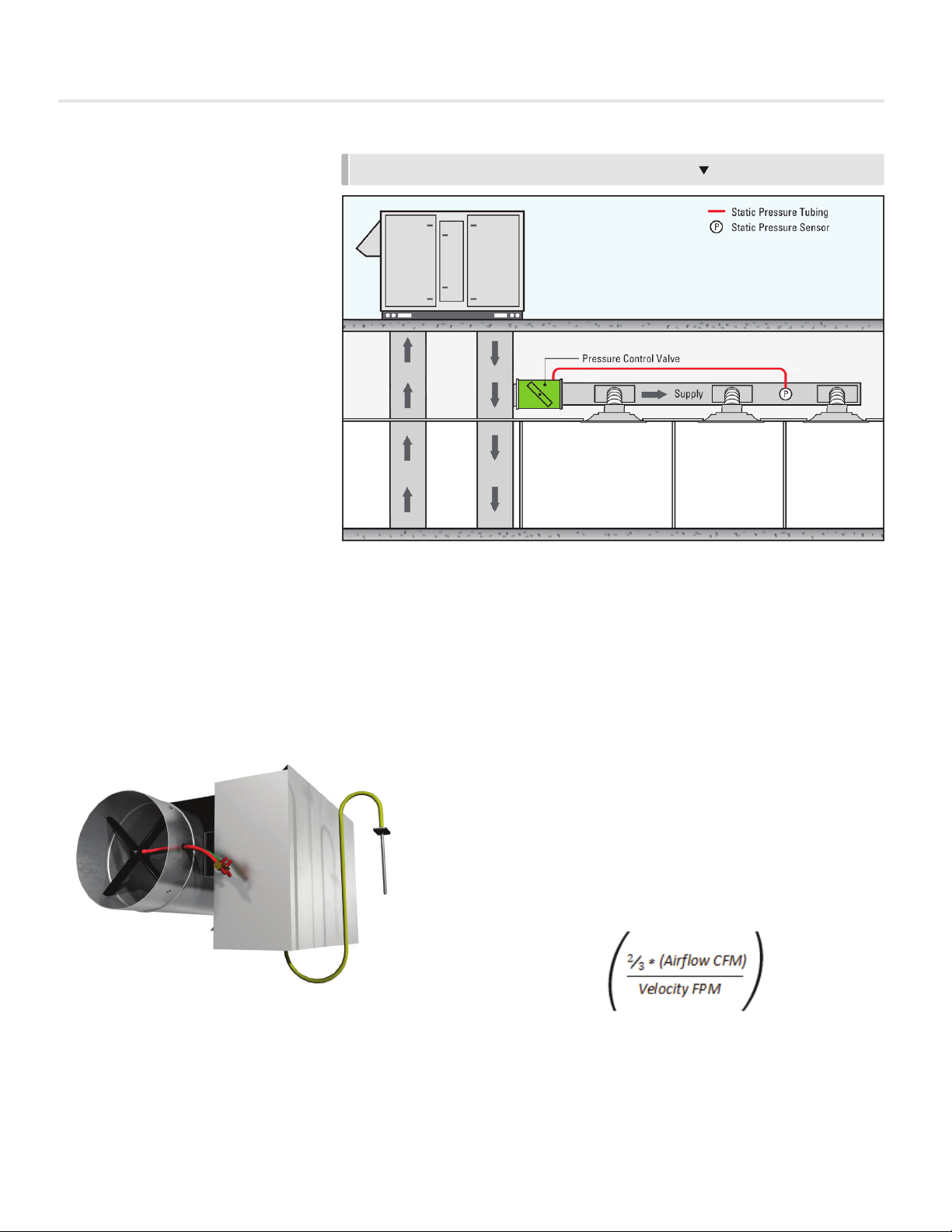
2. Static Pressure Probe – the PCV will come with a static
pressure probe. This probe needs to be installed about
2/3 of the way down the main supply duct run. Do not
mount this directly after the main fan, as the transducer
would read a very high static, rather than the average duct
static pressure. The probe then needs to be connected to
the HI side port of the transducer on the PIC board with
field provided ¼” pneumatic tubing. Leave the LO side
port of the transducer open to the atmosphere.
3. Power up the PCV controller. If a transformer is supplied,
then apply the appropriate line voltage to the transformer.
If a Price Power Module (PPM) is being used, plug in
the provided RJ12 cable into the power jack on the PIC
controller. The secondary of either transformer must be
earth grounded!
LCD Set-up Tool
The balancer will require an LCD-SETUP tool to set the static
pressure setpoint on the PCV controller, and to change any
parameters if needed. To connect the LCD-SETUP tool, the
balancer must connect to the PIC controller on the bypass
terminal in the ceiling, using the Service Port. (Note** the PCV
does not come with an LCD stat, so the LCD Set-up Tool is
required). If an LCD Set-up tool was not ordered for the job, an
existing LCD stat from a zone controller can be used as well;
you just require a CAT-5E (NETC35) cable to connect the tstat
to the controller
See page 16 for details on how to set the static pressure
setpoint.
1/4" TUBING
PCV CONTROLLER STATIC PRESSURE PROBE IN
THE SUPPLY DUCT
INSTALL 2/3 OF THE WAY DOWN MAIN DUCT
LCD CONNECTION EXAMPLE
LCD OR
LCD-SETUP RJ12 GREY CABLE
COMES WITH LCD-
SETUP TOOL
NOTE: When using CAT-5E (NETC35), connect to ethernet port on the back of the LCD thermostat.
CAT-5E (NETC35) BLUE CABLE
USING EXISTING LCD STAT
ONSITE

Mounting Instructions
Mount the PCV by sliding the actuator U-bolt over the damper
shaft. The back end of the PCV is secured by installing the
white plastic keeper (tied to the actuator motor with an elastic
band) with two sheet metal screws. This keeps the PCV from
moving when the actuator is turning, but still allows it to “float”
to avoid binding on the shaft if the controller were screwed
firmly in place.
Rotate the damper shaft all the way in one direction (either
clockwise or counter-clockwise) and then depress the gray
pivot clutch on the actuator, located directly below the green
terminal block, to unlock the actuator, and rotate it all the way
in the same direction the shaft was rotated in.
Tighten the nuts on the U-bolt clamp and secure the actuator
to the damper shaft.
Depress the clutch again and verify the actuator and shaft can
rotate through the full 90°range of motion.
NOTE: It does not matter if you choose clockwise or
counter-clockwise to rotate the shaft and actuator
before tightening the nuts. The PCV will calibrate on
power up. All that matters is that the damper shaft and
actuator have the full 90° range of motion.
Connect any of the controller's outputs as required.
NOTE: When the output loads require a switched HOT or
COMMON 24VAC signal. Use the jumper near the FAN output
to select HOT or COMMON outputs.
Power the PCV using 24VAC, the secondary 24VAC common
of the transformer must be earth grounded, or power with
Price PPM power module by plugging the supplied cables into
the RJ-12 power jacks.
Support: Having difficulty installing or configuring this product? Price is here to help.
Controls Application Support: 204.654.5613 | contr[email protected] | priceindustries.com/resources/type/literature
PLASTIC KEEPERPLASTIC KEEPER
CLUTCH
LOCATION
5
PRESSURE CONTROL VALVE
INSTALLATION
priceindustries.com |PRESSURE CONTROL VALVE - Manual

Support: Having difficulty installing or configuring this product? Price is here to help.
Controls Application Support: 204.654.5613 | contr[email protected] | priceindustries.com/resources/type/literature
Balancing Instructions
For more advanced setup details, please see 'Display Navigation' section.
Hold down the Menu button on the LCD Thermostat for
5 seconds until prompted for a passcode; use and
to enter the passcode; DOWN, UP, UP, DOWN.
The screen will now display “Service Menu: Application.”
Scroll down to the Balancing sub-menu.
Press the Menu button to enter this menu.
Screen will now show “Damper Override Disabled.” Press
Menu, and now “Disabled” will be flashing; this means you can
now scroll UP or DOWN with the arrow keys to select a target
to send the damper to.
For most applications, you will want to select “Go To Full
Open,” and once selected, the thermostat will read the damper
position and target position as the damper drives open.
5 SECONDS
THEN
SERVICE MENU:
APPLICATION
THEN
SERVICE MENU:
BALANCING
THEN
DPR OVERRIDE:
GOTO FULL OPN
POS. TARGET
50% 100%
DPR. OVERRIDE:
DISABLED THEN
6
PRESSURE CONTROL VALVE
DISPLAY NAVIGATION
PRESSURE CONTROL VALVE - Manual |priceindustries.com

7
PRESSURE CONTROL VALVE
DISPLAY NAVIGATION
priceindustries.com |PRESSURE CONTROL VALVE - Manual
Info Menu
(LCD & LCD Setup)
Once the PCV has 24VAC power applied to it and the LCD Setup Tool is plugged into the Service Port, the thermostat screen will
go through the initial start-up screen. The display should indicate that this is a Pressure Controller, and not something different.
To view basic information on the PCV controller, press the 'Menu' button once and scroll through with the 'Down' arrow
button.
APPLICATION
PRESSURE CTRL Air terminal, pressure controller, dual duct or fan powered terminal unit
VENT PRESSURE
0.150 IN H20 Current pressure reading
SUPPLYAIRTEMP
85.0F
If supply air temperature probe is not present, LCD will display no probe.
If supply air temperature probe is present, LCD will display temperature.
DAMPER POSITION
50%
This indicates the current position of the damper as percent (%)
Range is 0-100% (100% = full open or maximum air)
AIRHANDLER IS
ACTIVE
When pressure is sensed, this status is active.
When no pressure is sensed, status is inactive.
MAC ADDRESS 1 Shows the BACnet MAC address – range is 1-99
If no BACnet module attached, LCD will display MAC address None
DEVICE INSTANCE 101 Displays controller’s BACnet Device Instance (if BACnet module is attached)
Device Instance can range from 0-4, 194, 303
PRESS MENU
TO EXIT NOTE: Service menu will automatically time out after 20 seconds

8
PRESSURE CONTROL VALVE
DISPLAY NAVIGATION
PRESSURE CONTROL VALVE - Manual |priceindustries.com
Service Menu
(LCD and LCD Setup Only)
Hold down ‘Enter/Menu’ button for 5 seconds. Display will show ‘Passcode:’. Use Up and Down keys to enter the password in
this sequence: Down, Up, Up, Down.
SERVICE MENU:
APPLICATION Change the Application the unit is operating as
SERVICE MENU:
SETPOINT
Setup of Setpoint limits (day minimum/maximum)
°F/°C selection
SERVICE MENU:
DISCHARGEAIR TEMP
Setup of DAT HEAT and COOL setpoints
Shows discharge air temperature reading
SERVICE MENU:
SETPOINT
Setup of Setpoint limits (day minimum/maximum)
°F/°C selection
SERVICE MENU:
INPUT Allows setup of contact closure
SERVICE MENU:
OUTPUT
Allows setup of FAN, HEAT, COOL outputs
Allows setup of room light output (motion stat only)
Enable analog DAT control
SERVICE MENU:
BACNET
Allows setup of BACnet addresses
MAC address, Device Instance and Baud Rate
Included only if BACnet module is attached
SERVICE MENU:
STAT SETUP
Allows setup of LCD back lighting, sounds, motion sensor
Adjustment of HVAC and room lighting time-outs
SERVICE MENU:
P/C SETUP
Allows pressure setpoint and pressure deadband adjustment
Allows adjustment of damper
SERVICE MENU:
DIAGNOSTIC Load defaults and resets controller (recommended not to change)
PRESS MENU
TO EXIT NOTE: Service menu will automatically time out after 20 seconds
NOTE: In most cases only the BACnet and P/C setup menus will be needed for site setup. The configuration parameters in the other submenus are not applicable to the
PCV for the most part.

9
PRESSURE CONTROL VALVE
DISPLAY NAVIGATION
priceindustries.com |PRESSURE CONTROL VALVE - Manual
Application Menu
NOTE: The PCV already comes preset for Pressure Controller
Scroll through menu with Up and Down keys. Press ‘Enter/Menu’ button to apply your changes. *---Saving---* will display as your
changes are applied.
CONTROL APPLICATION AIR TERMINAL For typical single duct and fan powered units
FANCOIL 4 PIPE Fan coil terminals 4-pipe with hot and cold water
FANCOIL 2 PIPE Fan coil terminals 2-pipe with hot and cold changeover
DUAL DUCT Dual duct terminal units with hot and cold inlets
EXHAUST BOX Exhaust terminal unit typically with constant flow
FLOW FOLLOWER Volumetric offset application, typically for Venturi valves, but also for single ducts
MIXING BOX DAT Allows PIC to maintain discharged air temperature
CO2 TRACKING Tracks airflow to the current CO2 in the occupied space
PRESSURE CONTROLLER Allows PIC to maintain constant pressure
PRESS MENU
TO EXIT

10
PRESSURE CONTROL VALVE
DISPLAY NAVIGATION
PRESSURE CONTROL VALVE - Manual |priceindustries.com
Setpoint Menu
NOTE: Does not apply to pressure controller applications
(Setpoint Limits and Temperature Units)
Scroll through menu with Up and Down keys. Press ‘Enter/Menu’ button to apply your changes. *---Saving---* will display as your
changes are applied.
SETPOINT SET LOW LIMIT
65.0F
This is the lowest setpoint allowed
Range: 10.0°F - 100.0°F, Default: 65.0°F
SET HIGH LIMIT
80.0F
This is the highest setpoint allowed
Range: 10.0°F - 100.0°F, Default: 80.0°F
TEMPERATURE UNITS
FAHRENHEIT
Fahrenheit or Celsius
Default: °F
NIGHT HEAT SET
62.0F
PIC will maintain this heating setpoint when unoccupied
Range: 10.0°F - 100.0°F, Default: 62.0°F
NIGHT COOL SET
83.0F
PIC will maintain this cooling setpoint when unoccupied
Range: 10.0°F - 100.0°F, Default: 83.0°F
PROPORTIONAL BAND
2.0F
Default: 2°F, 1°C
Proportional Band is the raneg of control or the throttling range of the device
DAY DIFFERENTIAL
1.0F
1°F, 0.5°C
Day Differential is the deadband on either side of the setpoint
PRESS MENU
TO EXIT

11
PRESSURE CONTROL VALVE
DISPLAY NAVIGATION
priceindustries.com |PRESSURE CONTROL VALVE - Manual
Discharge Air Temperature Menu
NOTE: Thermostat must remain connected in this application
(Application Specific Options)
Scroll through menu with Up and Down keys. Press ‘Enter/Menu’ button to apply your changes. *---Saving---* will display as your
changes are applied.
DISCHARGETEMP DAT CTRL MODE
DAT HEAT/COOL
(when Analog DAT Control enabled)
DAT HEAT/COOL: When discharge air is 2° below room temp, it is considered cooling;
when discharge air is 2° above room temp, it is considered heating.
This mode is recommended because PCV (with DAT enabled) will monitor and use the
discharge air to control the analog outputs to help satisfy room load.
DAT HEAT ONLY, DAT COOL ONLY: Heat Only, Cool only always assumes cold or hot.
These modes are not recommended.
DISCHARGE AIR TEMP.
NO PROBE Current temperature of the probe mounted to water pipe
DAT COOL SETPOINT
55.0°F Cooling setpoint
DAT HEAT SETPOINT
90.0°F Heating setpoinit
DAT WHILE PI IS IN
DEADBAND 0.0°F The temperature that will be maintained when the system is satisfied
DAT UNOCC SET
DISABLED
DAT Unoccupied Setpoint.
Default: Disabled
DAT SERVICE TIME
60 SEC DAT will calculate and move the valve every 60 seconds (default)
DAT STEP DIVISION
3Distance a single step travels (leave at default 3)
DAT STEP MAXIMUM
10% Maximum change a call for heating or cooling can make during a step
DAT DIFFERENTIAL
2.0°F The range that the controller is satisfied and will not make adjustments
PRESS MENU
TO EDIT

12
PRESSURE CONTROL VALVE
DISPLAY NAVIGATION
PRESSURE CONTROL VALVE - Manual |priceindustries.com
Input Menu
Scroll through menu with Up and Down keys. Press ‘Enter/Menu’ button to apply your changes. *---Saving---* will display as
your changes are applied.
INPUT CONTACT CLOSURE
CONFIGURATION
All Output Halt - disables all output
Disable Binary Cool
Disable Binary Heat
Disable Binary Fan
Disable A04
Idle Analog Cool - default 0 VDC
Idle Analog Heat - default 0 VDC
Idle Analog ECM - default 1.5 VDC
Damper full close
Damper full open - Default
Occupied when closed - Forces occupied
Unoccupied on closed - Forces unoccupied
Not used - Disabled
PRESS MENU
TO EXIT

13
PRESSURE CONTROL VALVE
DISPLAY NAVIGATION
priceindustries.com |PRESSURE CONTROL VALVE - Manual
Output Menu – Heat
(Setup of Heat Outputs)
Scroll through menu with Up and Down keys. Press ‘Enter/Menu’ button to apply your changes. *---Saving---* will display as your
changes are applied.
OUTPUT
OUTPUT FAN
OUTPUT HEAT REHEAT TYPE
BINARY
Reheat Type: Binary, Hot Water, Binary/PWM, Hot Water/PWM
Binary uses Stage 1, 2, 3 - Default
Hot water uses Stage 1 & 2 for Open/Close
Binary/PWM and Hot Water/PWM - Stage 3 is PWM
DRIVE TIME
95 SECONDS
Hot water runtime in seconds
Not shown if binary heat is used
HEAT STAGE 1
1%
Heat Stage 1 Trip Point: Stage 1 engages at 1% heating
Not shown if hot water heat is used
HEAT STAGE 2
50%
Heat Stage 2 Trip Point: Stage 2 engages at 50% heating
Not shown if hot water heat is used
HEAT STAGE 3
100% Heat Stage 3 Trip Point: Stage 3 engages at 100% heating
AF INTERLOCK
DISABLED
Disabled: (Default) The controller will enable the heat as normal
Enabled: The heating outputs will not energize until at least 87.5%
REHEAT FAIL SAFE
DISABLED
Disabled – Outputs send 24VAC on call for heat
Enabled – Outputs send 24VAC when no call for heat (fail open valve in cold climates)
ANALOG HEAT MIN
0.0 VDC Outputs this voltage on heat analog pin when there is a minimum call for heating
ANALOG HEAT MAX
10.0 VDC Outputs this voltage on heat analog pin when there is a maximum call for heating
ANALOG HEAT IDLE
0.0 VDC Outputs this voltage on heat analog pin when there is no call for heating
PRESS MENU
TO EXIT
ANALOG DAT CONTROL Enable or disable Discharge Air Temperature control
PRESS MENU
TO EXIT

14
PRESSURE CONTROL VALVE
DISPLAY NAVIGATION
PRESSURE CONTROL VALVE - Manual |priceindustries.com
BACnet Menu
(BACnet Addressing Setup)
Scroll through menu with Up and Down keys. Press ‘Enter/Menu’ button to apply your changes. *---Saving---* will display as your
changes are applied.
BACNET MAC SET IN:
HARDWARE
Hardware - uses DIP switch on BACnet module for MAC Address - Default (not
recommended)
Software - uses STAT to set MAC Address - this overrides the hardware DIP switches
NOTE: the MAC Address (range 1-99) is added to the Device Instance
Example: MAC Address = 1, Device Instance = 100 - total address for this PIC would be
101
MAC ADDRESS
HARDWARE: 1
Display current MAC Address
NOTE: MAC Address only read on startup - see Device Instance below
DEVICE INSTANCE
This is the software BACnet address & must be unique on your building site
Range: 1 - 4, 194, 303
NOTE: After changing the Device Instance the STAT will send a Reset command to the PIC
to apply the address changes.
Addresses are only read on startupt, so after any changes you must reset the controller
either via STAT (which is automatic) or cycle 24VAC power
NOTE: Addresses are only read on startup to prevent a controller with faulty/damaged/
improperly set DIP switches from popping up all over a network, which would be extremely
difficult to troubleshoot
BAUD RATE 76800
This sets the BACnet MS/TP baud rate
9600 baud - slowest
19200 baud
38400 baud
76800 baud (Default baud rate for Price products) - fastest
PRESS MENU
TO EXIT

15
PRESSURE CONTROL VALVE
DISPLAY NAVIGATION
priceindustries.com |PRESSURE CONTROL VALVE - Manual
Stat Setup Menu
(Stat Options)
Scroll through menu with Up and Down keys. Press ‘Enter/Menu’ button to apply your changes. *---Saving---* will display as your
changes are applied.
STAT SETUP MOTION ENABLE OFF
(Motion Sensor STAT only)
Off - motion sensor disabled - default for regular LCD stat
On - motion sensor enabled (only enabled if you have a motion stat)
Only visible with motion stat
MOTION SENSITIVITY
5
(Motion Sensor STAT only)
Sets the sensitivity of the motion sensor
1 - least sensitive
9 - most sensitive
5 - default
Only visible when motion is enabled
HVAC TIMEOUT
240 MINUTES
PCV will go into unoccupied after no motion is detected and this timer expires
Default: 240 minutes
LIGHTS TIMEOUT
60 MINUTES
(Use room light output to select lighting signal)
PCV will turn off lighting output after no motion is detected and this timer expires
Default: 60 minutes
LCD BACKLIGHT
ALWAYS ON
Always on (default)
Always off
Button push - lights up on button press
BACK LIGHT COLOR
AQUA Change the back light color
SOUND OPTIONS
ON
On (default) - stat will beep when a user tries to exceed a limit
Off
CONTROLLER NAME Set a custom name for stat
PRESS MENU
TO EXIT

16
PRESSURE CONTROL VALVE
DISPLAY NAVIGATION
PRESSURE CONTROL VALVE - Manual |priceindustries.com
P/C Setup
(Pressure Controller Setup)
Scroll through menu with Up and Down keys. Press ‘Enter/Menu’ button to apply your changes. *---Saving---* will display as your
changes are applied.
P/C SETUP VENT PRESSURE
0.150 IN H20 Current pressure reading
PRESSURE SETPOINT
0.150 IN H2O
Pressure setting can be adjusted to maintain a constant duct static pressure (default: 0.150
in H2O)
CONTROL TYPE BYPASS
Bypass: (Default) Throttles the bypass valve to maintain constant pressure set point
Downstream: Constant pressure downstream - throttles the inline valve to maintain constant
downstream pressure setpoint
DEADBAND
0.030 IN H2O Deadband on either side of the pressure setpoint (default: 0.030 in H2O)
DPR RUNTIME
95 SEC Damper runtime in seconds (default: 95 sec, recommended not to change)
MAX STEP
5%
Maximum amount that output will be changed per step
Range: 1 - 50% (default: 5%)
AF FAIL NSB
ENABLED
Airflow Fail NSB (Night Setback) Enabled: PCV controller will go into unoccupied mode when
no pressure is measured
UNOCC DPR POS
50% If unoccupied signal is enabled, PCV damper will go into position (default: 50%)
PRESS MENU
TO EXIT

Network Wire Specifications
For the BACnet MS/TP network specific wire is required.
Do not use standard power or “thermostat” wire. This
wire does not have the necessary requirements for digital
communications. While it’s possible it may work (temporarily)
the network will be unreliable and not operating at optimal.
BACnet MS/TP Wire type recommendations
• Use 1 balanced twisted pair
• Low capacitance (17pF or less)
• Plenum rated (FT6, CMP ratings)
• 100-120 ohm, Balanced
• (CAT5, CAT5E, CAT6 network cable has excellent
specifications and will work in almost any BACnet MS/TP
application.)
• Price recommends using the Orange Compliment
for (+), the Orange for (-), and the Brown and Brown
Compliment for the (NET COM) connections. These
are paired in a standard CAT5E cable.
NOTE: NETCOM MUST BE WIRED
Termination
BACnet MS/TP networks must be terminated to ensure proper
operation. A network should be terminated twice, once at
the beginning and once at the end. Termination helps reduce
reflections and noise. The terminating can be done with a 100
ohm resistor across the + and - lines.
Tech Tip: The Price BACnet MS/TP to IP Router has built
in termination and it is enabled by default (since the router is
typically the beginning of the entire MS/TP network). Now you
only have to go and find/terminate that last device.
PIN 1
PIN 3
PIN 5
PIN 7
PIN 2
PIN 4
PIN 6
PIN 8
WIRING
ELECTRICAL NOISE EXAMPLE
HIGH VOLTAGE/
CURRENT LINE
BACNET NETWORK
Electrical Noise
Electrical noise can affect both analog signal and digital
communications such as BACnet. Therefore do not route
high voltage lines next to the BACnet network! Avoid noisy
electrical sources such as:
• Variable Frequency Drives
• High current power lines
(main panel feeds)
• Fluorescent light fixtures
If you must pass near noisy electrical lines cross at right
angles. This will help reduce the amount of noise coupled to
the network wires.
17
PRESSURE CONTROL VALVE
BACNET NETWORKING
priceindustries.com |PRESSURE CONTROL VALVE - Manual

Setting the MAC Address:
MAC (media access control) must be UNIQUE on an MS/TP network segment within building. An installer setting up an
MS/TP segment with 30 devices must ensure each device has a UNIQUE MAC Address (Range 1-99). The MAC Address
is set through the LCD thermostat.
BACnet Networking and Setup
NETWORK SEGMENT #1
NETWORK SEGMENT #2
Each device needs a unique MAC and Device Instance. All devices must be at the same baud rate. 24 VAC HOT and COMMON
polarities are critical and must not be reversed on ANY devices! Reverse polarity will stop communication on that MS/TP segment.
NET COM wire must be connected at each device and is critical for BACnet network reliability.
Use one twisted pair for + and -, and another twisted pair for NET COM for optimal noise cancellation.
TECH TIP
18
PRESSURE CONTROL VALVE
BACNET NETWORKING
PRESSURE CONTROL VALVE - Manual |priceindustries.com
Table of contents
Other Price Controllers manuals
Popular Controllers manuals by other brands

Daktronics
Daktronics All Sport 1600 Series Operation manual

RKC INSTRUMENT
RKC INSTRUMENT HA430 Operation manuals

AC Infinity
AC Infinity CONTROLLER 67 user manual

MarelliMotori
MarelliMotori M40FA640A/A Mark I user manual

Mitsubishi Electric
Mitsubishi Electric FX2NC-16EX-DS installation manual

Festo
Festo SPC200 Series manual