Price FHC User manual

MANUAL –INSTALLATION
Fume Hood Contoller/Monitor
FHC/FHMX Series
v300 –Issue Date: 05/31/17
© 2017 Price Industries Limited. All rights reserved.
Firmware Version: 1.6.0

pricecriticalcontrols.com |FUME HOOD CONTROLLER / MONITOR - Manual
Section 1 - Introduction
Product Overview.......................................................... 1
Features........................................................................ 1
Fume Hood Interface (FHI) Features ............................. 2
Sidewall Sensor (SWS) Features.................................... 2
Sash Position Sensor (SPS) Features ............................ 2
Presence Sensor (PS) Features ..................................... 2
Section 2 - Installation & Mounting
Fume Hood Controller (FHC) Installation & Mounting ..... 3
Fume Hood Monitor (FHMX) Installation & Mounting ..... 4
Sash Position Sensor (SPS) Installation & Mounting...... 5
Sidewall Sensor (SWS) Installation & Mounting .............. 7
Presence Sensor (PS) Installation and Mounting ........... 8
Wiring Diagram ............................................................. 9
Fume Hood Location Considerations .......................... 11
Section 3 - Sash, Sidewall & Hybrid Configuration
Control Settings .......................................................... 12
Fume Hood Interface (FHI) .......................................... 13
FHI - Initial Start Up ..................................................... 13
Information Menu ........................................................ 14
Service Menu .............................................................. 14
Section 4 - Interface And Menus
Control/Monitor ........................................................... 15
Alarm Points................................................................ 17
Occupancy ................................................................. 17
Input ........................................................................... 18
Output ........................................................................ 19
Network ...................................................................... 21
FHI Setup.................................................................... 21
Diagnostic ................................................................... 22
Section 5 - Setup Wizard
Setup Wizard .............................................................. 23
Section 6 - Balance And Verification
Balance & Verification .................................................. 25
Section 7 - BACnet Points List
BACnet Points List ...................................................... 26
FUME HOOD CONTROLLER / MONITOR
TABLE OF CONTENTS
This mark indicates an important point for the proper
function of the fume hood and the FHC. Improper
installation or setup may cause unit failure and
contamination of the laboratory space. Pay close
attention to all caution points throughout this manual.
CAUTION
IMPORTANT NOTES
Application Support
P: 204.654.5604
W: www.pricecriticalcontrols.com
Technical Support
P: 866.884.3524
E: pccfi[email protected]

1
FUME HOOD CONTROLLER / MONITOR
SECTION 1 - INTRODUCTION
FUME HOOD CONTROLLER / MONITOR - Manual |pricecriticalcontrols.com
Product Overview
Laboratory fume hoods serve as
ventilation systems that efficiently
exhaust chemical vapors, mist, and
fumes. Fume hoods also provide a
barrier protecting occupants from
certain reactions, spills, and even fires.
In most cases special fans exhaust the
fumes outside, which greatly dilute their
concentration and reduce their harmful
effects. In some cases a specialized
scrubber is also required to remove the
vapors from the exhaust air.
Fume hoods require constant exhaust
airflow to ensure that none of the air
entering the fume hood ever escapes
back into the laboratory space. This
ensures the safety of the user and of
any other occupants of the room or
building. The exhaust airflow, measured
in cubic feet per minute (CFM), creates
a face velocity across the sash opening.
This is the industry standard measure
of fume hood safety. Typically the
face velocity of a fume hood must be
between 80 – 100 feet per minute
(FPM), but this can vary based on local
codes or the fume hood design. It is
important to note the required face
velocity for the hood being used.
Features
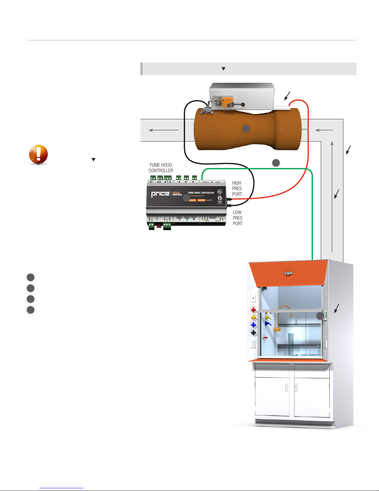
The Fume Hood Controller (FHC) can ensure a safe working environment by
constantly monitoring and adjusting the exhaust to maintain the correct face velocity.
The main control inputs are sash sensors and sidewall sensors. Sash sensors use a
potentiometer attached to the sash to measure the current height. Face velocity in
feet per minute (FPM) is calculated in real time. Sidewall sensors use an extremely
sensitive, low pressure sensor to measure the negative pressure in the hood
compared to the lab space. The Fume Hood Monitor (FHMX) constantly monitors
the fume hood face velocity and can provide real-time fume hood information to
operators and to the building management system (BMS) over BACnet.
• 16 bit – high speed flash based microprocessor with watch dog timer, brown
out reset
• Multi-stage surge protection against voltage spikes on 24 VAC input
• 2 simple connections to sidewall sensors using RJ-12 jacks
• 3 Sash position inputs (10kΩ)
• 2 binary outputs rated at 0.5 amps each, protected with thermal fuse
(RED LED on trip)
• 1 binary output (dry contact)
• 2 analog outputs (0-10 VDC)
• 2 binary inputs
• Pluggable terminal blocks
• Mnet high-speed fume hood network port
• 1 potentiometer input
• 1 pressure port input
• LED’s for Mnet/Lnet data TX/RX, Mnet/Lnet wiring fault, and RS-45 termination
A higher face velocity is not always
safer. Turbulence in the fume hood
can be created by high face velocities
causing issues with spillage/blowback.
CAUTION

2
FUME HOOD CONTROLLER / MONITOR
SECTION 1 - INTRODUCTION
pricecriticalcontrols.com |FUME HOOD CONTROLLER / MONITOR - Manual
Fume Hood Interface
(FHI) Features
• Backlit 14x2 LCD Interface with true
character display
• LED side bars offer 180 degree
viewing of current fume hood status
• Variety of colors displayed to
indicate fume hood status
• Password protected setup menu
• Easy to use MENU system for fast
and simple setup of system
• Included RJ45 plenum rated cable
for fast, error free hookup
• Setup Wizard – walk through setup
of FHC when first powered up
Sidewall Sensor (SWS) Features
• Ultra Low flow digital temperature
compensated pressure transducer
• 25 ft. sensor cable with quick-
connect installation
• Sidewall assembly with easy-to-
mount hardware
Sash Position Sensor
(SPS) Features
• Ultra long life potentiometer (over
250,000 cycles)
• Stainless steel cable for stability
• Metal mounting ring for stable
installation and reliability
• Thick plastic cover for protection
against airborne chemical agents
Presence Sensor (PS) Features
• Low profile device
• Adjustable coverage pattern
• Sensitive response
FUME HOOD INTERFACE
SIDEWALL SENSOR
SASH POSITION SENSOR
PRESENCE SENSOR

3
FUME HOOD CONTROLLER / MONITOR
SECTION 2 - INSTALLATION & MOUNTING
FUME HOOD CONTROLLER / MONITOR - Manual |pricecriticalcontrols.com
Fume Hood Controller (FHC)
Installation & Mounting
• Open the controls enclosure on the
Price Venturi Valve that is installed in
the fume hood exhaust duct.
• Follow the wiring diagram found
on page 10 for the FHC electrical
installation.
Required items:
1Venturi Valve
2Fume Hood Controller
3Fume Hood Interface
4RJ-45 Plenum Rated FHI Cable
INSTALLATION & MOUNTING
LOW
PRESSURE
PORT
HIGH
PRESSURE
PORT
DUCT
AIRFLOW
DIRECTION
The Fume Hood Controller is factory
mounted on the valve when ordered
with a Price Venturi Valve. Only electrical
installation is required.
Ensure the valve is facing the correct
direction and is mounted in the correct
orientation (vertical or horizontal).
CAUTION
VENTURI
VALVE
RJ-45 PLENUM
RATED FHI CABLE
FUME HOOD
CONTROLLER
1
4
FUME HOOD
INTERFACE
3
2

4
FUME HOOD CONTROLLER / MONITOR
SECTION 2 - INSTALLATION & MOUNTING
pricecriticalcontrols.com |FUME HOOD CONTROLLER / MONITOR - Manual
Fume Hood Monitor (FHMX)
Installation & Mounting
• The FHMX may arrive valve
mounted (see FHC Installation
& Mounting) or in a panel mount
controls enclosure. Open the
controls enclosure to access the
FHMX.
• Follow the wiring diagram found
on page 9 for the FHMX electrical
installation.
Required items:
1Fume Hood Monitor
2Fume Hood Interface
3RJ-45 Plenum Rated FHI Cable
INSTALLATION & MOUNTING
DUCT
AIRFLOW
DIRECTION
The Fume Hood Monitor is factory
mounted in an enclosure when ordered.
Only electrical installation is required.
Ensure that the panel-mount enclosure
is mounted in a location that can be
accessed for electrical installation.
CAUTION RJ-45 PLENUM
RATED FHI CABLE
FUME HOOD
MONITOR
3
FUME HOOD
INTERFACE
2
1

5
FUME HOOD CONTROLLER / MONITOR
SECTION 2 - INSTALLATION & MOUNTING
FUME HOOD CONTROLLER / MONITOR - Manual |pricecriticalcontrols.com
Sash Position Sensor (SPS)
Installation & Mounting
The sash sensor can be mounted in
one of four ways. Option A mounts
directly above the sash outside of the
fume hood. Options B and C mount to
the counter weight cable, and Option D
mounts directly in the hood.
Option A) Mount the sash sensor
above the sash as shown in Figure 1.
• Ensure the cable is free from
obstruction along the entire length
of sash movement.
• Ensure that the mounting position
of the end of the cable will not pass
above the sash sensor even at the
maximum sash height.
• Run the sensor cable back to the
FHC mounted on the venturi valve
or the FHMX.
Option B) Mount the sash sensor on
the top of the fume hood as shown in
Figure 2.
• Ensure the cable is free from
obstruction along the entire length
of sash movement.
• The sensor cable may be attached
directly to the counter weight.
This configuration may be desired
when the sash connects to the
counterweight with a belt and pulley
system.
• Run the sensor cable back to the
FHC mounted on the venturi valve
or the FHMX.
Option C) Mount the sash sensor on
the top of the fume hood as shown in
Figure 3 and 4.
• Ensure the cable clamp does not
pass around a pulley.
• Run the sensor cable back to the
FHC mounted on the venturi valve
or the FHMX.
• Ensure the sensor cable travels
parallel to the counter weight cable.
FIGURE 1 FIGURE 2
FIGURE 4
FIGURE 3

6
FUME HOOD CONTROLLER / MONITOR
SECTION 2 - INSTALLATION & MOUNTING
pricecriticalcontrols.com |FUME HOOD CONTROLLER / MONITOR - Manual
FIGURE 5
The sash position sensor cable must be
mounted as close to parallel as possible
with the direction of the sash movement.
Any angle can cause improper sash
height readings and result in poor
control.
CAUTION
Option D) Mount the sash sensor on
the inside wall of the fume hood as
shown in Figure 5. This is the least
preferable mounting option, as the
sensor is directly in the exhaust air
stream.
• Ensure that the sensor and cable
to not interfere with the mechanical
operation of the fume hood sash.
• Ensure the sensor is as close to the
sash as possible so that the cable is
completely parallel to the sash in all
positions.
• Raise the sash to the fully open
position (not just the working
height). Screw the metal ring into
the sash. Ensure that the sensor is
mounted higher than the fully open
position of the sash.
• Once mounted, raise and lower the
sash several times to ensure that
the cable is clear of all obstructions
and moves freely with the sash.
• Run the sensor cable back to the
FHC mounted on the venturi valve
or the FHMX.
If only one SPS is required, the
SPS must be wired into the SASH
POSITION SENSOR #1 port on the
FHC/FHMX.
CAUTION

7
FUME HOOD CONTROLLER / MONITOR
SECTION 2 - INSTALLATION & MOUNTING
FUME HOOD CONTROLLER / MONITOR - Manual |pricecriticalcontrols.com
Sidewall Sensor (SWS) Installation
& Mounting
• The sidewall sensor consists of
multiple components: The Sidewall
Sensor, two hollowed bolts, a
male brass pressure port, and kink
resistant tubing.
• With the sash in the fully open
position, drill a 5/16” hole
5” above and 5” inward from
the base of the sash. Mount the
Sidewall Sensor behind the fume
hood wall, in the fume hood plenum
using one of the hollow bolts.
• To mount the exterior hollow bolt,
drill a 5/16” hole on the front of the
fume hood, no more than 12”
away from the Sidewall Sensor.
• Attach the provided male brass
pressure port to the exterior hollow
bolt.
• Use the kink-resistant tubing to
attach the brass pressure port from
the SWS to the brass pressure port
on the exterior hollow bolt.
• Attach the sensor cable to the SWS
and run the cable back to the FHC
mounted on the venturi valve or the
FHMX.
Mounting position is critical to ensure
the accuracy of the SWS. Ensure that
there are no sharp bends or kinks in the
tubing during the installation. Improper
installation will cause failure of the SWS.
CAUTION
INSTALLATION & MOUNTING LOCATION
INSTALLATION & MOUNTING DETAILS
KINK
RESISTANT
TUBING
SENSOR
CABLE
BRASS
PRESSURE
PORT
MALE BRASS
PRESSURE PORT
HOLLOWED
BOLT #2 HOLLOWED
BOLT #1
SIDEWALL
SENSOR
THE SIDEWALL SENSOR IS
MOUNTED BEHIND THE WALL, IN
THE FUME HOOD PLENUM, USING A
HOLLOWED BOLT PROVIDED.
Required items:
1Side Wall Sensor
2Hollowed Bolt x2
3Male Brass Pressure Port
4Sensor Cable
5Kink Resistant Tubing
4
2
3
5
1
If only one SWS is required, the SWS
must be wired into the SIDEWALL
SENSOR #1 port on the FHC/FHMX.
CAUTION

8
FUME HOOD CONTROLLER / MONITOR
SECTION 2 - INSTALLATION & MOUNTING
pricecriticalcontrols.com |FUME HOOD CONTROLLER / MONITOR - Manual
Presence Sensor (PS) Installation
and Mounting
1. Remove the cover of the presence
sensor by placing the blade of a
small screwdriver in the notch in
the right side of the cover as shown
(see Figure 1). Always remove the
cover in this manner.
2. Drill two screw pilot holes and one
wire passage according to the
template in Figure 2.
3. Insert mounting screws partially
into holes. Route the wire harness
through the wire passage hole as
shown in Figure 3.
4. Route the wire harness through
the hole in the presence sensor.
Install the presence sensor onto the
mounting screw and tighten.
5. Replace the cover by engaging
the left side first and then gently
snapping the cover into place
FIGURE 1 - INSERT SMALL SCREWDRIVER AND PRY UPWARDS
FIGURE 3 - WIRE HARNESS
FIGURE 4 - MOUNTED PRESENCE SENSOR
FIGURE 2 - MOUNTING TEMPLATE
POWER CABLE
MOUNTING SCREW
FIGURE 5 - PRESENCE SENSOR FACTORY SETTINGS
Remember to follow these safety
precautions:
• Shut off power to the FHC or
FHMX before wiring the sensor.
• Always ensure wiring is
located clear of any moving
parts to avoid damage.
CAUTION

9
FUME HOOD CONTROLLER / MONITOR
SECTION 2 - INSTALLATION & MOUNTING
FUME HOOD CONTROLLER / MONITOR - Manual |pricecriticalcontrols.com
Ensure proper voltage is available if a transformer is available
in the enclosure. Double check all labels and wiring before
applying high voltage.
1. Ensure disconnect switch is off. Route high voltage line to
L1/L2(N) terminal block using knockout/cable clamp
(by others).
2. Connect blue RJ-45 (network type 8 position) plenum-
rated cable to jack labeled Interface on the FHC /FHMX.
Connect the other end to the back of the FHI mounted on
the side of the fume hood.
3. If using a Sash Position Sensor, connect it to the Sash 1
terminal block. The green LED indicator will light up when
the FHC is powered on and the Sensor is detected.
4. If using a Sidewall Sensor, connect it to the Sidewall
Sensor 1 jack. The green LED indicator will light up when
the FHC/FHMX is powered on and the Sensor is detected.
The FHC is a 24 VAC low voltage controller. Do not apply any
voltage above 24 VAC to controller.
CAUTION
Wiring Diagram
WIRING DIAGRAM - FHMX
FHMX
CONNECTION TO FUMEHOOD NETWORK
From previous LSC/FHMX/FHC to next FHC/FHMX

10
FUME HOOD CONTROLLER / MONITOR
SECTION 2 - INSTALLATION & MOUNTING
pricecriticalcontrols.com |FUME HOOD CONTROLLER / MONITOR - Manual
WIRING DIAGRAM - FHC
MODULAR CABLE PROVIDED BY PRICE
FIELD ELECTRICAL WIRING
FACTORY ELECTRICAL WIRING
LEGEND
FHC
OUTPUTS
LINKER INTERFACE
SENSOR
SIDEWALL
COM
1
2
BI1
BI2
BO1
STA
COM
24
VAC
NET OUT
TX
RX
NOTES:
•FHI DISPLAY WIRED WITH
CAT-5 CABLE WITH MODULAR
RJ-45 CONNECTORS. CABLE
SUPPLIED WITH FHC
•TRANSFORMER SECONDA
RY
MUST BE GROUNDED
*
AO1
AO2
BO2
BO3
COM
CAT5E CABLE BY PRICE
STA
FUME HOOD CONTROLLER
Mute
NORMAL ALARM
Enter
Menu
Emergency
SASH POSITION SENSORS
1
2
3
1
SENSOR
SIDEWALL
2
POT
VENTURI
NET IN
TRM
FLT
HLH
NETWORK
FUME HOOD
PRESSURE TAPS
TO VENTURI
LOW
HIGH
ABC
ACTUATOR
2
1
3
FACTORY CONNECTED
FACTORY CONNECTED
TO VENTURI
CONTROL ARM
SASH POSITION SENSOR
120/24V TRANSFORMER
TYPICALLY MOUNTED/CONNECTED
SHIPPED LOOSE
AT TOP OF FUME HOOD
FUME HOOD DISPLAY INTERFACE
FACTORY MOUNTED TO VALVE
FACTORY MOUNTED
GREEN - RLY NC
WHITE - RLY COM
BROWN - RLY NO
BLACK - COM
RED - 24VAC
Fume Hood Network
From Previous LSC (or FHC)
to next FHC
RJ -12 CABLE
BY PRICE
SIDEWALL VELOCITY SENSOR
Presence Sensor
Power In
120V

11
FUME HOOD CONTROLLER / MONITOR
SECTION 2 - INSTALLATION & MOUNTING
FUME HOOD CONTROLLER / MONITOR - Manual |pricecriticalcontrols.com
CORRECT FUMEHOOD LOCATION
INCORRECT FUMEHOOD LOCATION
Fume Hood Location
Considerations
• Ensure supply/exhaust overhead
diffusers/returns are installed away
from fume hood. Direct airflow
running across the ceiling and then
down the face of the fume hood
will greatly affect the SIDEWALL
SENSOR and general performance
of the hood
• Ensure hood is located away from
pedestrian traffic and doors
• Ensure fume hood has all
components installed properly
– such as air foils and sills. Any
missing components can greatly
affect the commissioning of the
hood. Balancing of the face velocity
should not be done if any of these
components are missing.
The location of the fume hood
and overhead diffusers is critical
to proper safety and performance.
These guidelines will ensure the
effectiveness of the fume hood.
CAUTION

12
pricecriticalcontrols.com |FUME HOOD CONTROLLER / MONITOR - Manual
FUME HOOD CONTROLLER / MONITOR
SECTION 3 - SASH, SIDEWALL & HYBRID CONFIGURATION
Control Type Response
Time Accuracy Face
Velocity
Airflow
Control Stability
Monitor N/A High Measured N/A N/A
Sash
Sensor Control Fast Moderate Calculated Yes Stable
Sidewall
Sensor Control Moderate High Measured Yes Stable
Hybrid Control Fast High Measured Yes Stable
Control Settings
No Control - Monitor Only
This choice disables all control.
Sidewall Sensor Control
This method measures the face velocity
over the sash opening by measuring
the pressure inside the fume hood. This
method will control face velocity.
Sash Sensor Control
This method calculates the face velocity
using the dimensions of the fume hood
opening and the current CFM. This
method will control face velocity.
Hybrid Control
This method is an optimized
combination of both sidewall sensor
and sash sensor control. It is the most
effective method of fume hood control
and is recommended in all cases.
Hybrid Control is only available if
both a sidewall sensor and a sash
sensor are connected.
The device will now only monitor the
face velocity of the unit, but will not
change the airflow or face velocity of the
unit.
CAUTION

13 FUME HOOD CONTROLLER / MONITOR - Manual |pricecriticalcontrols.com
FUME HOOD CONTROLLER / MONITOR
SECTION 4 - INTERFACE AND MENUS
Mute
NORMAL ALARM
Enter
Menu
Emergency
Up Button
Used for menu selection and adjustment – press
both Up and Down arrows at same time to display
interface Startup screens.
Down Button
Used for menu selection and adjustment – press
both Up and Down arrows at same time to display
interface Startup screens.
Mute
Used to temporarily mute the local alarm for a
certain number of minutes.
Menu/Enter
Used to Enter service menu(s). The setup menu(s)
are password protected.
Emergency
Used to trigger emergency mode. Local Alarm
will sound and BACnet point will change to Alarm
alerting the front end system.
Fume Hood Interface (FHI)
FHI - Initial Start Up
When the FHI is first powered from the FHC/FHMX, it will display the following information: (When on the default display screen
press both UP/DOWN at same time to show this screen.)
PRICE ELECTRONICS
FHI STANDARD MODEL
FHI VERSION 3.XX
LOADING: 0-100 %
FHC/FHMX VERSION 1.XX
FACE VELOCITY
PRICE ELECTRONICS Start-up screen
FHI STANDARD MODEL Interface
FHI VERSION 3.XX Fume Hood Interface - Firmware Version V3.xx or
higher
LOADING: 0-100 % Loading Screen – Thermostat pulls in variables
FHC VERSION 1.XX Firmware Version
FACE VELOCITY
100 FPM
After start up LCD will display default screens
depending on mode of operation

14
pricecriticalcontrols.com |FUME HOOD CONTROLLER / MONITOR - Manual
FUME HOOD CONTROLLER / MONITOR
SECTION 4 - INTERFACE AND MENUS
Service Menu
The service menu contains all setup and configuration parameters. Each FHC ships with factory defaults, but virtually all settings
can be adjusted in the field. All MAIN menus are listed on this page. Use the WIZARD and/or menus shown to setup the FHC for
your application.
NOTE: To access the service menu hold ‘Enter/Menu’ for 5 seconds and enter the passcode. This menu is passcode protected for
safety.
CTRL/MONITOR
ALARM POINTS
OCCUPANCY
INPUTS
OUTPUTS
NETWORK
FHI SETUP
DIAGNOSTIC
Information Menu
Pressing the Enter/Menu button from the default display screen will open this menu.
VALVEPRESSURE
AIRFLOW
SASH 1 HEIGHT
SASH 2 HEIGHT
SASH 3 HEIGHT
SASH OPEN
VELOCITY TRGT
CONTROL METHOD
OCCUPANCY
VALVEPRESSURE Displays the current Venturi Valve pressure (in.w.c.) when present.
AIRFLOW Displays the current airflow device airflow rate (CFM).
SASH 1 HEIGHT Displays the current height of Sash Sensor 1 (in.)
SASH 2 HEIGHT Displays the current height of Sash Sensor 2 (in.)
SASH 3 HEIGHT Displays the current height of Sash Sensor 3 (in.)
SASH OPEN Displays the current percentage of open sash area (%)
VELOCITY TRGT Displays the current face velocity target (FPM)
CONTROL METHOD Displays the current face velocity control method.
OCCUPANCY Displays the current occupancy state of the fume hood
CTRL/MONITOR Manual setup menu for control and monitor methods
ALARM POINTS Manual setup menu for alarm points
OCCUPANCY Configure occupancy and override options
INPUTS Configure the functions of the binary inputs
OUTPUTS Configure the functions of the binary and analog outputs
NETWORK Choose network type (BACnet or Mnet)
FHI SETUP Configure the FHI such as display options, LED color, alarm type, etc.
DIAGNOSTIC Provides manual control and monitoring of variables.

15 FUME HOOD CONTROLLER / MONITOR - Manual |pricecriticalcontrols.com
FUME HOOD CONTROLLER / MONITOR
SECTION 4 - INTERFACE AND MENUS
Control/Monitor
CONTROL METHOD HYBRID
SASH CTRL
SIDEWALL CTRL
NO CONTROL
FALLBACK CTRL SW FALLBACK
NO FALLBACK
MONITOR METHOD SASH MONITOR
SW MONITOR
OCC. SETPOINT
DEADBAND
SETBACKSETPNT
OFFDAMPERPOS.
MIN CFM
MAX CFM
SETBACKMINCFM
OFFREPORT0CFM
CTRL/MONITOR: SIDEWALL SW READ MODE
FREEZE VALVE
SENSOR SCALE
FACE VELOCITY
SENSOR OFFSET
SIDEWALL MENU:ZEROSWSENSOR
SIDEWALLMENU: SIDEWALL PID
CTRL/MONITOR: SASH SASH MENU: CALIBRATE SASH CALIBRATING: SASH # MAX HEIGHT
MIN HEIGHT
FULLY OPEN SASH
CLOSE SASH
SASH WIDTH
SASH MENU: SASH CTRL SASH CTRL METHOD LINEAR CAL.
CAL. FROM SW
CAL. MANUALLY
SASH SCALE
SASH OFFSET
CTRL/MONITOR: VALVE AIRFLOW CAL VALVE
CFM SCALE
CFM OFFSET
When using the FREEZE VALVE setting, all airflow control
aspects of the FHC will be disabled. Remember to disable
FREEZE VALVE to restore control.
CAUTION

16
pricecriticalcontrols.com |FUME HOOD CONTROLLER / MONITOR - Manual
FUME HOOD CONTROLLER / MONITOR
SECTION 4 - INTERFACE AND MENUS
CTRL METHOD: HYBRID A hybrid control method uses both a Sash Position Sensor (SPS) and a Sidewall Sensor (SWS) to control the face velocity.
CTRL METHOD: SASH CTRL A sash control method uses a Sash Position Sensor (SPS) to calculate the required ariflow to maintain face velocity based upon the measured sash position.
CTRL METHOD: SIDEWALL CTRL A sidewall control method uses a Sidewall Sensor (SWS) to adjust airflow to maintain face velocity based upon the pressure differential between the fume
hood and the space
CTRL METHOD: NO CONTROL Airflow will not be controlled. A sidewall or sash position sensor may still be used to monitor face velocity
FALLBACK CTRL If SW FALLBACK selected, the fallback control method will use the SWS in the event that the primary control method malfunctions. Only an option when
sash control method is selected and there is a SWS detected.
MONITOR METHOD If SASH MONITOR selected, the position of the sash and the current airflow will be used to display the calculated face velocity. If SW MONITOR selected,
the face velocity will be displayed based on the differential pressure measurement provided by the Sidewall Sensor
OCC. SETPOINT Sets the face velocity target of the fume hood in Occupied Mode. The velocity can range from 60 FPM to 150 FPM
DEADBAND The range at which the face velocity target is satisfied. Example: The deadband is set to 10 FPM and the face velocity target is 100 FPM. At any face
velocity between 90 and 110 FPM, the control loop is satisfied and current face velocity will display at 100 FPM. Set the deadband to
CAL MODE for a deadband of 0 FPM.
SETBACKSETPNT Sets the face velocity target when the fume hood is in setback mode. The velocity can be set to 0 FPM or in the range of 60 to 150 FPM. To reach 0 FPM,
press and hold the down key.
OFFDAMPERPOS. Off Damper Position sets the actuator position of the airflow device when the fume hood is turned off. Setting this to 0% will be a closed damper position,
setting this to 100% will be a fully open damper position.
MIN CFM Sets the minimum allowable airflow for the fume hood. This is a scheduled value. The airflow can range from 0 to 10000 CFM
MAX CFM Sets the maximum allowable airflow for the fume hood. This is a scheduled value. The airflow can range from 0 to 10000 CFM
SETBACKMINCFM Sets the minimum allowable airflow for the fume hood when in Setback. This is a scheduled value. The airflow can range from 0 to 10000 CFM
OFFREPORT0CFM If set to YES, Airflow will be reported as 0 CFM regardless of current conditions when the Fume Hood is in Off mode.
CTRL/MONITOR: SIDEWALL This menu allows for adjustments to the sidewall sensor (SWS).
SW READ MODE This menu is visible if multiple sidewall sensors are available. Selecting HIGHEST SENSOR will use the highest reading SWS to report face velocity.
LOWEST SENSOR will use the lowest reading SWS to report face velocity. AVG SENSOR will average all SWS readings. SENSOR 1 or 2will provide only
that SWS reading.
FREEZE VALVE Freeze the airflow device at its current position. This setting is used when measuring the face velocity while balancing the fume hood.
SENSOR SCALE Adjust the reading of the SWS by using a multiplying factor. Example: If the SWS is displaying 100 FPM and the balancer’s equipment is displaying 85 FPM,
set the sensor scale to 0.850. The range is 0.5 to 2.0.
FACE VELOCITY Read only value displaying the current face velocity that is read by the sidewall sensor including adjustments made by SENSOR SCALE and
SENSOR OFFSET.
SENSOR OFFSET Adjust the reading produced by the sidewall sensor by using an offset. Example, if the SWS is displaying 85 FPM and the blancer’s equipment is reading
100 FPM, set the sensor offset to be 15 FPM. This should be a secondary balancing tool. The range is -20 to 20 FPM
SIDEWALL MENU: ZEROSWSENSOR Zero the SWS. Ensure that both the interior and exterior sensor openings are properly sealed before starting this calibration.
If a SWS is plugged in after initial set-up, it will have to be zeroed before it will be functional.
SIDEWALLMENU: SIDEWALL PID The speed the controller responds to the changes in the SWS reading. PID factors are represented as a single number between 0 and 10 with 0 being the
slowest repsonse and 10 beign the fastest response.
CTRL/MONITOR: SASH This menu allows for adjustments to the sash position sensor (SPS).
MAX HEIGHT Set the maximum height of the sash. This is the fully open position which may be above the working height. The height is the distance measured in the
direction of the SPS movement.
MIN HEIGHT Set the minimum height of the sash in its fully closed position. This position is measured from the bottom of the sash to the work surface. This should not
be measured from the bottom of the sash to the fume hood airfoil.
FULLY OPEN SASH The operator should move the sash to the MAX HEIGHT. Once at the MAX HEIGHT, press OK.
CLOSE SASH The operator should move the sash to the MIN HEIGHT. Once at the MIN HEIGHT, press OK.
SASH WIDTH Set the fixed width of the sash. This is not the width of the fume hood but of the sash.
LINEAR CAL. The airflow provided will be calculated using the sash position and the face velocity target. Flow = Height * Width * Face Velocity
CAL. FROM SW The airflow provided is mapped to the SPS based upon the SWS reading to meet the face velocity target. When selected, the user will be asked to open
the sash to various heights and verify that the face velocity signal is stable at each height. For multiple SPS’s, all sashes need to be moved to the required
position for each stage of the Cal.
CAL. MANUALLY The airflow provided is mapped to the SPS based upon face velocity readings measured by face velocity measuring device to meet the face velocity target.
For multiple SPS’s, all sashes need to be moved to the required position for each stage of the Cal.
SASH SCALE Adjust the airflow provided at a given sash opening position by using a multiplying factor. Example, if the balancer is reading 120 FPM, and the fume hood
is at 100 FPM, set the sash scale to 1.2. The range is 0.5 to 2.0
SASH OFFSET Adjust the airflow provided at a given sash opening position by using an offset. Example, if the sidewall sensor is displaying 85 CFM and the Balancer is
reading 100 FPM, set the Sensor Offset to be 15 FPM. This should be a secondary balancing tool, the sash scale is a more accurate tool. The range is 0
to 20 FPM
CAL VALVE Calibrate the venturi valve. This should be performed any time airflow set points are changed, after an actuator is replaced, after a power failure, or after
clutching and manually moving an actuator
CFM SCALE Adjust the factory calibration of a valve. This function is used when the reported valve airflow does not match a balancers traverse readings when the valve
is operating within design pressure limits. Use the CFM Scale to apply a multiplying factor to the valve airflow. The range is 0.5 to 2.0. NOTE: Need to Cal
Valve after changing this setting.
CFM OFFSET Adjust the factory calibration of a valve. This function is used when the reported airflow valve airflow does not match a balancers traverse readings when
the valve is operating within deign pressure limits. Use the CFM Offset to adjust the airflow by an offset factor. The range is (-10 000) to 10 000 CFM.
NOTE: Need to Cal Valve after changing this setting.

17 FUME HOOD CONTROLLER / MONITOR - Manual |pricecriticalcontrols.com
FUME HOOD CONTROLLER / MONITOR
SECTION 4 - INTERFACE AND MENUS
Alarm Points
LOW FPM ALARM
HIGHFPM ALARM
SETBACKLOWFPM
SETBACK HIFPM
FPM ALARMHGHT
SASHHGHTCAUTN
SASHHGHTALARM
SB ALARM HGHT
LOPRESS ALARM
HIPRESS ALARM
LOW CFM ALARM
HIGHCFM ALARM
ALARM POINTS:ALARM DELAYS FACE VELOCITY
VALVEPRESSURE
AIRFLOW
SASHHGHTCAUTN
LOW FPM ALARM Set the Low Face Velocity Alarm. Face Velocity below this value will
activate an alarm in Occupied mode. The value ranges from 1 - 100
FPM or can be disabled.
HIGHFPM ALARM Set the High Face Velocity Alarm. Face Velocity above this value will
activate an alarm in Occupied mode. The value ranges from 100 -
200 FPM or can be disabled.
SETBACKLOWFPM Set the Setback Low Face Velocity Alarm. Face Velocity below this
value will activate an alarm in Setback mode. The value ranges from
0 - 100 FPM.
SETBACK HIFPM Set the Setback High Face Velocity Alarm. Face Velocity above this
value will activate an alarm in Setback mode. The value ranges from
60 - 200 FPM or can be disabled.
FPM ALARMHGHT Below the FPM Alarm Height value, High Face Velocity alarms are
disabled. For example setting the FPM Alarm Height to 3 inches will
disable High Velocity Alarm when the sash is less than 3 inches. This
value ranges from 0 to 25 inches. This function reduces nuisance
alarms in the closed sash position.
SASHHGHTCAUTN Set the Sash Caution Height. Sash positions greater than this value
will activate a Caution status in Occupied mode. The value ranges
from 0 to 25 in.
SASHHGHTALARM Set the Sash Alarm Height. Sash positions greater than this value will
activate Alarm Mode in Occupied Mode. The value ranges from 0 to
25 in. Sash Alarm Height will override Sash Caution Height.
SB ALARM HGHT Set the Setback Sash Alarm Height. Sash positions greater than this
value will activate Alarm Mode in Setback Mode. The value ranges
from 0 to 25 in.
LOPRESS ALARM Set the Low Valve Pressure Alarm. Venturi Valve static pressure below
this value will activate an Alarm. The value ranges from 0 to 5.0 in.w.c
or can be disabled.
HIPRESS ALARM Set the High Valve Pressure Alarm. Venturi Valve static pressure
above this value will activate an Alarm. The value ranges from 0 to
5.0 in.w.c or can be disabled.
LOW CFM ALARM Set the Low Airflow Alarm. Airflow below this value will activate an
Alarm. This value ranges from 0 to 10000 CFM or can be disabled.
HIGHCFM ALARM Set the High Airflow Alarm. Airflow above this value will activate an
Alarm. This value ranges from 0 to 10000 CFM or can be disabled.
FACE VELOCITY Delay for the Face Velocity Alarm. This delay ranges from 0 and 30
seconds
VALVEPRESSURE Delay for the Valve Pressure Alarm. This delay ranges from 0 and 30
seconds
AIRFLOW Delay for the Airflow Alarm. This delay ranges from 0 and 30 seconds
SASHHGHTCAUTN Delay for the Sash Height Caution. This delay ranges from 0 and 30
seconds
Occupancy
OCC OVERRIDE FACE VELOCITY
VALVEPRESSURE
AIRFLOW
SASHHGHTCAUTN
NO OVERRIDE The occupied status of the Fume Hood is not overridden.
FORCE SETBACK Occupancy is currently forced to setback mode. All Setback options
will now be active
FORCE OCC Occupancy is currently forced to Occupied operation. All Occupied
options will now be active
FORCE OFF Occupancy is currently forced to Off. The FHC is not monitoring
or controlling airflow or face velocity. All alarms and cautions are
inactive

18
pricecriticalcontrols.com |FUME HOOD CONTROLLER / MONITOR - Manual
FUME HOOD CONTROLLER / MONITOR
SECTION 4 - INTERFACE AND MENUS
Input
BI1 CONFIG UNUSED
SETBACKONCLOS
SETBACKONOPEN
OFF ON CLOSED
OFF ON OPENED
ALARMONCLOSED
CAUTIONONCLOS
EMERGPURGONCL
BI2 CONFIG SAME OPTIONS AS ABOVE
BI1STBKOFFDLY
BI2STBKOFFDLY
UNUSED The Binary input is unused
SETBACKONCLOS The FHC/FHMX will change to Setback mode when the Binary Input
is Closed
SETBACKONOPEN The FHC/FHMX will change to Setback mode when the Binary Input
is Opened
OFF ON CLOSED The FHC/FHMX will turn Off when the Binary Input is Closed
OFF ON OPENED The FHC/FHMX will turn Off when the Binary Input is Opened
ALARMONCLOSED The FHC/FHMX will alarm when the Binary Input is Closed
CAUTIONONCLOS The FHC/FHMX will activate Caution mode when the Binary Input is
Closed
EMERGPURGONCL The FHC will start an emergency purge and will fully open the venturi
valve when the Binary Input is Closed. The FHI will also Alarm.
BI1STBKOFFDLY This option will only be available when Binary Input 1 is configured
for Setback and Off Mode. This option sets the delay for the binary
inputs desired action after it is triggered
BI2STBKOFFDLY This option will only be available when Binary Input 2 is configured
for Setback and Off mode. This option sets the delay for the binary
inputs desired action after it is triggered
This manual suits for next models
1
Table of contents
Other Price Controllers manuals