Price BFC Series User manual

MANUAL – SERVICE + INSTALLATION
BACnet Flow Controller for Fan Filter Units
BFC Series
v400 –Issue Date: 02/18/21
© 2021 Price Industries Limited. All rights reserved.

BACNET FLOW CONTROLLER
TABLE OF CONTENTS
Product Overview
General Information....................................................... 1
Installation & Mounting Instructions
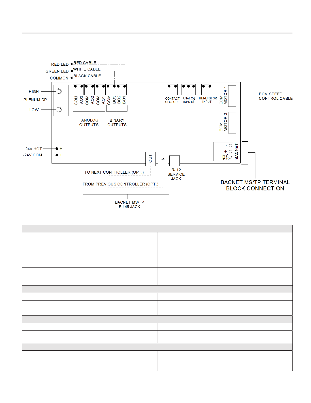
Typical Wiring ................................................................ 2
Input/Output Description ............................................... 2
Display Navigation
Initial Startup ................................................................. 3
Main Menu .................................................................... 4
Service Menu ................................................................ 5
Service Menu – Fan....................................................... 6
Service Menu – Filter ..................................................... 7
Service Menu – I/O........................................................ 8
Service Menu – BACnet ................................................ 9
Service Menu – Diagnostics .......................................... 9
Filter Calibration
Filter Calibration using BFC Interface ........................... 10
Filter Calibration over BACnet...................................... 11
Networking & Setup
BACnet Wiring ............................................................ 12
Termination ................................................................. 12
Electrical Noise............................................................ 12
Network Wire Specifications........................................ 13
BACnet Service Menu ................................................. 14
BACnet Networking and Setup ................................... 15
Setting the Device Instance (Coupled MAC and DI) ..... 16
Setting the Device Instance (De-coupled MAC and DI) 17
Network Layout........................................................... 18
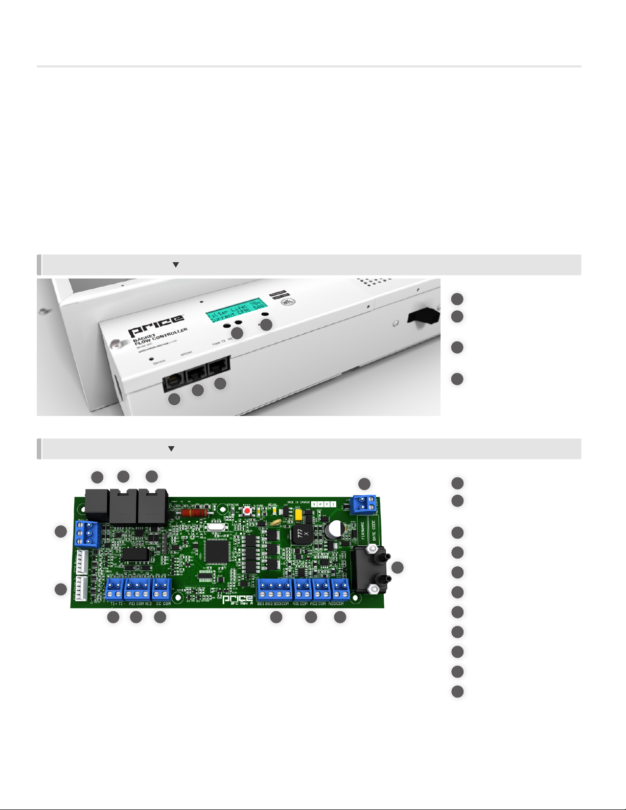
Package/Component Identification.............................. 20
Location...................................................................... 21
Mounting..................................................................... 22
BAS Input Signal ......................................................... 23
Analog RPM Feedback................................................24
Wiring and Cables ....................................................... 25
Maintenance
Troubleshooting........................................................... 26
Specifications.............................................................. 27
BACnet points list for BFC firmware v3.1.0.................. 28

1
priceindustries.com |BACNET FLOW CONTROLLER - Manual
BACNET FLOW CONTROLLER
PRODUCT OVERVIEW
General Information
The BACnet Flow Controller (BFC) is a DDC fan controller designed specifically for controlling flow through Fan Filter Units (FFU)
with EC motor technology. The BFC controls an EC motor through a local setpoint which is adjustable using a push button
interface on the BFC, by an analog BAS input voltage, or over BACnet.
In addition to fan control, the BFC can monitor filter pressure drop, filter loading, signal for filter changes, monitor the motor and
filter lifetime in hours, as well as report airflow and air temperature over the filter. This information can be viewed from the LCD
screen on the front of the BFC controller, or over BACnet on a building management system.
NOTE: This manual only covers the BFC controller. For troubleshooting an ECM motor, please visit http://www.priceindustries.com
and download the ECM Motor Troubleshooting Manual.
BACK OF BFC CONTROLLER
FRONT OF BFC CONTROLLER
1
34
1
2
3
4
Service Port RJ12 Jack
BACnet Connection RJ45
Jacks
Up and Down arrow
buttons for navigation
Menu button for info
menu and entering
Service menus
22
7
8
4
3
11
5
6
9
10
1
2
Service Port RJ12 Jack
BACnet Connection RJ45
Jacks
24 VAC Power Connection
Pressure Transducer
0-10 VDC Analog Outputs
24 VAC Binary Outputs
Contact Closure
Analog Inputs
Thermistor Input
Motor #1 Jack
BACnet MS/TP Terminals
55
6
12
23
4
10
11
789

2BACNET FLOW CONTROLLER - Manual |priceindustries.com
BACNET FLOW CONTROLLER
INSTALLATION & MOUNTING INSTRUCTIONS
Typical Wiring
Input/Output Description
Analog Outputs
AO1
Configurable for Unit Pressure, CFM (Air Flow), RPM
(Motor Speed), Filter Load , BAS, *LED Dimming, *LED
On/Off (*for UFFU w/ BACnet Dimming Control)
AO2
Configurable for Unit Pressure, CFM (Air Flow), RPM
(Motor Speed), Filter Load , BAS, *LED Dimming, *LED
On/Off (*for UFFU w/ BACnet Dimming Control)
AO3
Configurable for Unit Pressure, CFM (Air Flow), RPM
(Motor Speed), Filter Load , BAS, *LED Dimming, *LED
On/Off (*for UFFU w/ BACnet Dimming Control)
24 VAC Binary Outputs
BO1 Red LED out
BO3 Green LED out
COM COMMON
Analog Inputs
AI1 Input voltage for remote fan speed control
AI2 Input voltage for LED control (*for UFFU
w/ BACnet Dimming Control)
Inputs
Thermistor Input Analog input for monitoring air over filter
temperature, 10k type J thermistor
Contact Closure Binary input to activate secondary ECM setpoint.

3
priceindustries.com |BACNET FLOW CONTROLLER - Manual
BACNET FLOW CONTROLLER
DISPLAY NAVIGATION
Initial Startup
When the BFC controller is powered up with 24VAC it will display the following information.
PRICE
ELECTRONICS Start–up screen
BFC
VERSION Displays firmware version
CURR
PRESSURE Displays the current static pressure in in. w.g.
ECM SETPOINT Displays ECM setpoint in % motor speed
UNIT STATUS Displays current unit status (Off, Low Pressure, Normal, Filter Loaded)
CONTROL MODE Displays the current control mode (BACnet, BAS, Local Control)
CURRENT CFM Displays the current airflow (only visible with the Constant Flow motor program)
*LCD display will cycle between Curr Pressure, ECM Setpoint, Unit Status, Control Mode, and Current CFM during normal
operation.
Change ECM motor setpoint using and arrow keys
LOCAL ECM
58% Setpoint will save after being adjusted with arrow keys
NOTE: Local setpoints are stored to EEPROM and will remain set after power failures.

4BACNET FLOW CONTROLLER - Manual |priceindustries.com
BACNET FLOW CONTROLLER
DISPLAY NAVIGATION
Main Menu
From the Home Screen press the Menu button to enter this menu. Use Up and Down arrow buttons to navigate through.
FILTER LOAD Read Only - Displays % of filter loading based on new, clean filter pressure drop
ECM SPEED Read Only - Displays the current RPM of the motor
LOCAL ECM Displays local ECM Setpoint.
Press the Menu button then use the arrow keys to change the ECM Setpoint. Press menu again to save.
LOCAL DIMMING Displays local LED Dimming Setpoint (for UFFU w/ BACnet Dimming Control).
Press the Menu button then use the arrow keys to change the Dimming Setpoint. Press Menu again to save.
MAC ADDRESS Read Only - Displays device MAC Address
DEVICE INST Read Only - Displays device Instance
PRESS MENU
TO EXIT
NOTE: Local setpoints are stored to EEPROM and will remain set after power failures.

5
priceindustries.com |BACNET FLOW CONTROLLER - Manual
BACNET FLOW CONTROLLER
DISPLAY NAVIGATION
Service Menu
Hold down Menu button for 5 seconds, display will show ‘Passcode’. Use Up and Down arrow buttons to enter this sequence:
Down, Up, Up, Down.
SERVICE MENU
FAN
Allows you to see or adjust:
Current CFM
CFM Offset
CFM Tweak
ECM Setback
Fan Type
Unit Size ie. 2X2
Wheel Type
Voltage Type
Motor Runtime (in hours)
Reset Motor Runtime
SERVICE MENU
FILTER
Filter Load
Load Trip
Current Pressure
Filter Type
Filter Runtime (in hours)
Reset Filter
SERVICE MENU
I/O
Analog In 1 (BAS ECM SP)
Analog In 2 (BAS LED SP)
Analog Out 1 (Present Value)
Analog Out 1 (AO1 Usage)
Analog Out 2 (Present Value)
Analog Out 2 (AO2 Usage)
Analog Out 3 (Present Value)
Analog Out 3 (AO3 Usage)
SERVICE MENU
BACNET
MAC Address
Device Instance
Baud Rate
RS-485 Termination
BACnet Reset
SERVICE MENU
DIAGNOSTICS
Restore Defaults
Total Device Reset
Factory Configuration Reset

6BACNET FLOW CONTROLLER - Manual |priceindustries.com
BACNET FLOW CONTROLLER
DISPLAY NAVIGATION
Service Menu – Fan
Press Menu button to enter this menu. Use Up and Down arrow buttons to navigate through.
CURRENT CFM
XXXX CFM Read Only
UNIT STYLE Supply, Exhaust, CARES
NOTE: Must match actual configuration of FFU
UNIT SIZE
2X2
Displays the ECM motor calibration for FFU nominal size (2x2)
Selectable sizes are: 2’ x 2’, 2’ x 3’, 2’ x 4’
NOTE: Must match actual configuration of FFU.
WHEEL TYPE
XXX
Adjust unit wheel type from FC to BC. Read only varying on fan type and unit size
The wheel type is factory set, but it can be adjusted only under the Constant Torque setting. From there, you can set the
wheel type to BC on 2’ x 3’ and 2’ x 4’ units only.
NOTE: BC wheel type is for Constant Torque only.
VOLTAGE TYPE
XXX Adjust unit voltage type from 115/240/277.
MOTOR PROGRAM
XXX Adjust fan type from Constant Volume to Constant Torque. Airflow (CFM) will be hidden if fan type is constant torque
MOTOR RUNTIME
0 HRS Read Only – Displays number of hours on motor since last reset
RESET MOTOR
RUNTIME Resets Motor Runtime
CFM OFFSET
0 CFM
Adjust airflow reading +/- up to 500 CFM to coincide with balancer measured airflow
Example: flow hood reads 550 CFM
Airflow reading on BFC is 500 cfm
Adjust CFM offset to +50 CFM
CFM TWEAK
100 %
Adjust airflow reading between 50 to 200%
Example: flow hood reads 550 CFM
Airflow reading on BFC is 500 cfm
Adjust CFM tweak to +110%
ECM SETBACK Secondary setpoint for use in turndown or night setback applications. This is activated upon contact closure.
PRESS MENU
TO EXIT

7
priceindustries.com |BACNET FLOW CONTROLLER - Manual
BACNET FLOW CONTROLLER
DISPLAY NAVIGATION
Service Menu – Filter
Press Menu button to enter this menu. Use Up and Down arrow buttons to navigate through.
FILTER TYPE
XXX
Adjust filter type, BTR, RSR.
BTR = Bench Top Removable RSR = Room Side Removable
FILTER LOAD
XX % Read Only - Displays % of filter loading based on new, clean filter pressure drop
LOAD TRIP
1.50
This represents the ratio between clean and loaded filter pressure. It is factory set for 1.5 times the clean filter pressure.
Example: If the filter calibrated pressure is 0.16 in. w.g., the loaded filter pressure will be 0.24 in. w.g.
FILTER RUNTIME
0 HRS Read Only – Displays number of hours on filter since last reset
RESET
FILTER
Resets Filter Runtime.
Activate this to calibrate filter pressure during initial setup or filter replacement.
PRESS MENU
TO EXIT

8BACNET FLOW CONTROLLER - Manual |priceindustries.com
BACNET FLOW CONTROLLER
DISPLAY NAVIGATION
Service Menu – I/O
Press Menu button to enter this menu. Use Up and Down arrow buttons to navigate through.
BAS (AI1)
0 VDC Read Only – Displays current input BAS voltage for motor speed control
AI2 (BAS LED)
0 VDC Read Only – Displays input voltage to Analog Input 2 for LED control (UFFU w/ BACnet Dimming Control only)
CONTACT CLOSURE Displays current state of binary contacts used for night setback / secondary ECM setpoint (open / closed)
AO1 USAGE
FILTER LOAD (DEFAULT)
Configure Analog Output 1 for:
Unit Press - Unit Pressure; Range (0 in. w.g. to 2 in.w.g.)
CFM - Airflow; Range (0 - 5000 CFM)
RPM - Range (0 - 2500 RPM). See page 11 for RPM details.
Filter Load - Range (0 - 100%)
BAS - 0-10VDC signal to BAS
LED Dimming (0 - 100%)
LED On/Off (Changes autonomously Based on LED Dimming value)
Disabled
AO1 PRESVAL
0 VDC Read Only - Present Value for Analog Output 1
AO2 USAGE
UNIT PRESSURE
(DEFAULT)
Configure Analog Output 2 same as AO1 options shown above.
AO2 PRESVAL
0 VDC Read Only - Present Value for Analog Output 2
AO3 USAGE
BAS (DEFAULT) Configure Analog Output 3, same as AO1 options shown above.
AO3 PRESVAL
0 VDC Read Only - Present Value for Analog Output 3
PRESS MENU
TO EXIT

9
priceindustries.com |BACNET FLOW CONTROLLER - Manual
BACNET FLOW CONTROLLER
DISPLAY NAVIGATION
Service Menu – BACnet
MAC ADDRESS
1
Sets unit’s MAC address
NOTE: the MAC address (range 1-99) is added to the device instance.
Example: MAC address = 1, device instance = 100, total address for this BFC would be 101
DEVICE INST
0, 000, 101
This is the ‘software’ BACnet address and must be unique to your building site.
Range: 1 – 4,194,303
BAUD RATE
76800
BAUD RATE
This sets the BACnet MS/TP baud rate
9600 baud (all BACnet devices must at least support this speed) – slowest
19200 baud
38400 baud
76800 baud (default baud rate for Price products) - fastest
RS-485 TERM,
DISABLED Enable and disable RS-485 termination on MS/TP segment.
RESTORE BACNET
DFLTS Reset MAC Address, Device Instance, and BAUD rate to default values.
PRESS MENU
TO EXIT
Service Menu – Diagnostics
RESTORE
TTLDEV RESET Full device reset, removes all order information including unit configuration. Does not change any BACnet settings.
RESTORE
FACTORY CONFIG Resets device to factory settings without changing any BACnet settings.
PRESS MENU
TO EXIT

10 BACNET FLOW CONTROLLER - Manual |priceindustries.com
BACNET FLOW CONTROLLER
FILTER CALIBRATION
Filter Calibration
To properly track filter loading, the BFC must be calibrated with the clean filter pressure. Before proceeding, ensure the unit is
operating at the desired airflow. Any changes to the airflow will change the unit pressure and therefore require the filter status to be
reset. For further information on airflow balancing please refer to the FFU Manual. Filter calibration can be performed either directly
through the BFC interface or over BACnet. Each method is described below.
Using the BFC Interface
STEP 1: To calibrate clean filter pressure drop, scroll through the ‘Service Menus’ until reaching ‘Filter’. Select this menu by
pressing the ‘Enter/Menu’ button (far right).
NOTE: To enter the Service Menu, hold down the ‘Enter/Menu’ button for 5 seconds. Display will show ‘Passcode’. Use
the Up and Down arrow buttons to enter this sequence:
Down, Up, Up, Down.
STEP 2: Scroll through the ‘Filter’ menu until reaching ‘Reset Filter’, select by pressing the ‘Enter/Menu’ button.NOTE: Make sure
the area directly beneath and around the unit is clear of any personnel or equipment as this can affect the reading of the
clean filter static pressure.
STEP 3: Press the ‘Enter/Menu’ button to confirm reset of filter; this will begin calibration. This will take approximately 2 minutes.
After filter calibration is complete, LCD will display:
‘RESET COMPLETED’.
FILTER RESET SCREEN FILTER CALIBRATION SCREEN

11
priceindustries.com |BACNET FLOW CONTROLLER - Manual
BACNET FLOW CONTROLLER
FILTER CALIBRATION
Object Name Units Default Range Description R/W
AI5 Unit Pressure in. w.g. Dynamic Dynamic Current differential pressure measured across the filter R
AV1 Filter Load % 0 0-100% Current percent of filter loading based on new, clean filter
pressure drop R
AV2 Filter Runtime Hours 0 0-99999 Current number of hours on filter since last reset. Enter
value of zero after filter has been replaced and calibrated. R/W
AV3 Motor Runtime Hours 0 0-99999 Current number of hours on motor since last reset R
AV4 Airflow cfm N/A 0-9999 Current airflow R
AV5 Filter Calibrated
Pressure in. w.g. N/A Dynamic Unit pressure when filter was calibrated R
AV6 Filter Trip
Pressure in. w.g. 0 Dynamic Filter trip pressure R
AV7 Filter Loading
Trip Point Numeric 1.5 1-3 Set filter loading trip point R/W
Via BACnet
The steps below require the BFC to be configured and set up on a BACnet front-end system.
For further information on BFC BACnet setup, see Networking & Setup section.
STEP 1: Ensure that BACnet point AV2 – Filter Runtime is being pulled in (see table below).
STEP 2: Write a value of 0 to AV2 – Filter Runtime. This will initiate a calibration cycle. The current unit pressure (AI5) will be
automatically be copied to the Filter Calibrated Pressure (AV5). This process takes approximately 2 minutes.
NOTE: Filter loading can subsequently be monitored using BACnet point: AV1 – Filter Load (from 0% clean to 100% loaded).

12 BACNET FLOW CONTROLLER - Manual |priceindustries.com
BACNET FLOW CONTROLLER
NETWORKING & SETUP
FROM
PREVIOUS
DEVICE
TO NEXT
DEVICE
BACNET WIRING
BACnet Wiring
The Price BACnet Flow Controller (BFC) has the option of
using a CAT 5 cable to run BACnet MS/TP, or cable hardwired
into a pluggable terminal block (see next page if using
hardwired BACnet connections). The RJ-45 jacks for use with
the supplied BACnet cables are directly tied to the pluggable
terminal block, and so any combination of supplied cables
and hardwired connections can be used on a single network
segment.
BACnet networks must be run in a daisy chain configuration,
meaning there is only one main cable and each network device
is connected directly along its path, with no more than 30
devices per segment, and MS/TP segment lengths must not
exceed 1050 feet.
Termination
BACnet MS/TP networks must be terminated to ensure proper
operation. A network should be terminated twice, once at
the beginning and once at the end. Termination helps reduce
reflections and noise. The terminating can be done with a 100
ohm resistor across the + and - lines. Termination can also be
done via software using the Price BACnet Flow Controller. For
more information see the BACnet Service Menu section of this
manual.
Tech Tip: The Price BACnet MS/TP to IP Router has built
in termination and it is enabled by default (since the router is
typically the beginning of the entire MS/TP network). Now you
only have to go and find/terminate that last device.
Electrical Noise
Electrical noise can affect both analog signal and digital
communications such as BACnet. Therefore do not route
high voltage lines next to the BACnet network! Avoid noisy
electrical sources such as:
• Variable Frequency Drives
• High current power lines
(main panel feeds)
• Fluorescent light fixtures
If you must pass near noisy electrical lines cross at right
angles. This will help reduce the amount of noise coupled to
the network wires.
ELECTRICAL NOISE EXAMPLE
HIGH VOLTAGE/
CURRENT LINE
BACNET NETWORK

13
priceindustries.com |BACNET FLOW CONTROLLER - Manual
BACNET FLOW CONTROLLER
NETWORKING & SETUP
Use Price supplied CAT-5 cables for BACnet whenever
possible. If not possible to use Price supplied cables,
follow these wire specifications.
Network Wire Specifications
For the BACnet MS/TP network specific wire is required.
Do not use standard power or “thermostat” wire. This
wire does not have the necessary requirements for digital
communications. While it’s possible it may work (temporarily)
the network will be unreliable and not operating at optimal
performance.
BACnet MS/TP Wire type recommendations
• Use 2 balanced twisted pairs, one for + and -, one for
NET COM
• Low capacitance (17pF or less)
• Plenum rated (FT6, CMP ratings)
• 100-120 ohm, Balanced
• (CAT5, CAT5E, CAT6 network cable has excellent
specifications and will work in almost any BACnet MS/TP
application.)
• Price controllers use the Orange Compliment
for (+), the Orange for (-), and the Brown and
Brown Compliment together for the (NET COM)
connections. These are paired in a standard CAT5E
cable. Pre-terminated CAT5 cables are available from
Price. Model code: NETC35 (35 ft plenum rated cable,
terminated with RJ45 plugs, 568-B standard)
PIN 1
PIN 3
PIN 5
PIN 7
PIN 2
PIN 4
PIN 6
PIN 8
WIRING
Use RJ45 jacks for BACnet connection, or 3 position terminal
block for 3-wire connection (+, -, NET COM) NET COM must
be wired.

14 BACNET FLOW CONTROLLER - Manual |priceindustries.com
BACNET FLOW CONTROLLER
NETWORKING & SETUP
BACnet Service Menu
Each controller’s MAC address, Device Instance, and Baud rate are set in the BACnet sub-menu of the service menu accessed
through the LCD screen on the face of the BFC. For information on how to select a MAC address and Device instance for any
controller on a network, see following pages.
To set the controller’s BACnet settings, enter the Service Menu and adjust settings as follows:
NOTE: When the screen displays a flashing value, that value is ready to be changed and can be adjusted by pressing the arrow
keys. Pressing Menu will save the value.
Hold down the Menu button on the LCD Thermostat for
5 seconds until prompted for a passcode; use and
to enter the passcode; DOWN, UP, UP, DOWN.
The screen will now display “SERVICE MENU: FAN”
Scroll down to the BACnet sub-menu.
Press the Menu button to enter this menu.
Screen will now show “MAC ADDRESS = 1”. This is the
default setting and can be programmed between 1 and 99 by
pressing Menu and using the UP and DOWN arrows ( ).
Use to scroll to whatever MAC you are intending to set this
controller to, once you arrive at the number, press Menu to
save
NOTE: By default, the MAC address will appear as the last 2
digits of the device instance.
5 SECONDS
THEN
SERVICE MENU:
FAN
THEN
SERVICE MENU:
BACNET
MAC ADDRESS THEN
The device instance defaults to 100, but will be displayed with
the last 2 digits as the MAC if the previous screen was set to
enabled. Press Menu then use the arrow keys to change the
device instance.
NOTE: Each Menu press will change allow changes in different
tiers of the device instance (so that you don’t have to scroll for
extended periods to get into the millions range – supposing
that’s where you need to set your device instance)
The baud rate is the speed that the MS/TP network runs at.
EVERY device on the network must run at the same speed.
Price controllers are defaulted to a baud rate of 76800, but can
be changed to 38400, 19200, or 9600. For a network segment
with all Price controllers, it’s recommended that the baud rate
be left at 76800.
*Choose lower baud rates only when integrating with devices
by other manufacturers whose maximum speed is lower than
76800 (eg. 38400).
THEN
THEN
OR
OR
DEVICE INST.
101
BAUD RATE
76800
Once all settings are made scroll down to the ‘Press Menu to Exit’ screen and press Menu. The controller will then re-start which
will save these values.

15
priceindustries.com |BACNET FLOW CONTROLLER - Manual
BACNET FLOW CONTROLLER
NETWORKING & SETUP
BACnet Networking and Setup
Setting the MAC Address:
MAC (media access control) must be UNIQUE on an MS/TP network segment within building. An installer setting up an MS/
TP segment must ensure each device has a UNIQUE MAC Address (Range 1-99). The MAC Address is set through the LCD
thermostat or LCD setup tool.
NOTE: Each device on a network segment must be set to run at the same speed or baud rate.
NETWORK SEGMENT #1
NETWORK SEGMENT #2
24 VAC power HOT and COMMON polarities are critical and must not be reversed on ANY devices! Reverse polarity will stop
communication on that MS/TP segment. All 24 VAC transformers must be grounded on their secondary side for BACnet to work.
NET COM wire must be connected at each device and is critical for BACnet network reliability.
Use one twisted pair for + and -, and another twisted pair for NET COM for optimal noise cancellation.
TECH TIP
Net CoM
Net CoM
Net CoM
Net CoM

16 BACNET FLOW CONTROLLER - Manual |priceindustries.com
BACNET FLOW CONTROLLER
NETWORKING & SETUP
Setting the Device Instance (Coupled MAC and DI)
Device Instance:
A Device Instance number identifies a device within an entire building, therefore giving it a unique number or Address,
much like a telephone ext. number. A building can have one telephone number, but all the extensions have a unique
number to identify them. A Device Instance number would work the same way and must be unique throughout the building.
Below is a table defining how a Device Instance number is obtained.
NOTE: Each device on a network segment must be set to run at the same speed or baud rate.
Example Device Instance setup with Default settings:
• MAC Address = 6 (6 x 1 = 6) – Set through software
+
TIER 1 = 58 (58 x 100 = 5800) – Set through software
+
TIER 2 = 1 (1 x 10,000 = 10,000) – Set through software
+
TIER 3 = 0 (0 x 1,000,000 = 1,000,000) – Set through software
=
Final Device Instance = 0,015,806
Description Default Value (Factory) Notes
MAC Address 6 Value: limited to 1-99
Tier 1 (x100) 58 Value: limited to 0-99
Tier 2 (x10,000) 1 Value: limited to 0-99
Tier 3 (x1,000,000) 0 Value: limited to 0-4
0 01 58 06
Tier3
Multiplier
Tier2
Multiplier
Tier1
Multiplier
MAC
Address

17
priceindustries.com |BACNET FLOW CONTROLLER - Manual
BACNET FLOW CONTROLLER
NETWORKING & SETUP
Setting the Device Instance (De-coupled MAC and DI)
Device Instance:
A Device Instance number identifies a device within an entire building, therefore giving it a unique number or Address, much like a
telephone ext. number. A building can have one telephone number, but all the extensions have a unique number to identify them. A
Device Instance number would work the same way and must be unique throughout the building.
Below is a table defining how a Device Instance number is obtained.
NOTE: Each device on a network segment must be set to run at the same speed or baud rate.
Example Device Instance setup with Default settings:
• TIER 1 = 4 (4 x 1 = 4) – Set through software
+
TIER 2 = 58 (58 x 100 = 5800) – Set through software
+
TIER 3 = 1 (1 x 10,000 = 10,000) – Set through software
+
TIER 4 = 0 (0 x 1,000,000 = 1,000,000) – Set through software
=
Final Device Instance = 0,015,806
Description Example Value Notes
Tier 1 (x01) 4 Value: limited to 1-99
Tier 2 (x100) 58 Value: limited to 0-99
Tier 3 (x10,000) 1 Value: limited to 0-99
Tier 4 (x1,000,000) 0 Value: limited to 0-4
0 01 58 04
Tier4
Multiplier
Tier3
Multiplier
Tier2
Multiplier
Tier1
Multiplier

18 BACNET FLOW CONTROLLER - Manual |priceindustries.com
BACNET FLOW CONTROLLER
Network Layout
The BFC can be connected over BACnet MS/TP and added to an existing BAS front end system. Price also offers its own mini
front-end system known as FFU-BFC-FE which acts as a graphics package. The Price WEB Server allows the user to view
variables such as filter status, CFM, etc. for each FFU and modify setpoints as needed.
Devices
Webserver: Provides the graphical web interface, plugs into IP Router. 2000 node capacity.
IP Router: Acts as interface between Internet and internal system. 5 ports. 1 Port for Building WAN (Internet/Building Network –
You cannot plug a BACnet Router or IP Switch into this port). 4 LAN Ports available (Used for BACnet Routers and IP Switches).
BACnet Router: Interfaces between BACnet MS/TP system and IP Router (internet). Supports 30 FFU.
IP Switch: Expands available connections for BACnet router. 5 ports.
CONNECTION EXAMPLE (LESS THAN 30 UNITS)
NETWORKING & SETUP
BACnet MS/TP to
BACnet IP Router
FFU 1 FFU 2 FFU 3
FFU 30 FFU 4
Network
Connection
IP Router
Webserver Interface
FFU 1
CFM- 312
FIlterHours - 1280
FilterStatus - Clean
ANTEROOM
FFU 2
CFM- 310
FIlterHours - 1125
FilterStatus - Clean
FFU 3
CFM- 312
FIlterHours - 1225
FilterStatus - Replace
FFU 4
CFM- 310
FIlterHours - 1300
FilterStatus - Clean
FFU 5
CFM- 312
FIlterHours - 1430
FilterStatus - Clean
FFU 6
CFM- 315
FIlterHours - 1400
FilterStatus - Replace
FFU 7
CFM- 312
FIlterHours - 1350
FilterStatus - Clean
Webserver
Other manuals for BFC Series
1
This manual suits for next models
1
Table of contents
Other Price Controllers manuals
Popular Controllers manuals by other brands

Omron
Omron CVM1 Series Operation manual

GE
GE PACSystems* RX3i Application guide

Johnson Controls
Johnson Controls M9310-HGA-3 installation guide

C-COM Satellite Systems
C-COM Satellite Systems iNetVu 7710 user manual

YOKOGAWA
YOKOGAWA FA-M3 Vitesse technical information

iTechworld
iTechworld 40Amp MPPT user guide

PEELLE
PEELLE 254-EN INSTALLATION & INTERFACE GUIDE

Siemens
Siemens Raja+ 3TE7431-2BC24-1A Series Installation, Maintenance & Troubleshooting Guide

Apeks
Apeks XL4 SECOND STAGE Maintenance manual

Genius
Genius BRAIN 06 24V manual

Rosslare
Rosslare AYC-F/Gx4 Series Installation and programming manual

IFM
IFM AE1300 operating instructions