SECTION 1: NO POWER ....................................................................................................... 4
SECTION 2: POWER CHAIR WILL NOT DRIVE DUE TO SYSTEM LOCK ........................... 8
NE or NE+ Electronics ..................................................................................................................................... 8
Q-Logic Electronics ......................................................................................................................................... 9
SECTION 3: ERROR CODE DIAGNOSTICS ....................................................................... 10
Battery Charging or Drive Inhibit .................................................................................................................... 11
Open Motor Error .......................................................................................................................................... 14
Motor/Brake Error .......................................................................................................................................... 16
Missing or Defective Module ......................................................................................................................... 17
Joystick Error ................................................................................................................................................ 18
Power Module Communications or Software Error ........................................................................................ 19
Low Battery Voltage ...................................................................................................................................... 20
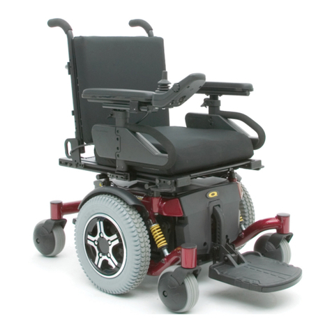
Table 1: Q6 Edge with NE Electronics Error Codes ...................................................................................... 24
Table 2: Q6 Edge with NE+ Electronics Error Codes .................................................................................... 26
Table 3: Q6 Edge with Q-Logic Error Codes ................................................................................................. 29
Appendix 1: Connector Reference Guide ..................................................................................................... 30
Appendix 2: Common Action Reference Guide ............................................................................................ 31
TABLE OF
CONTENTS
WARNING! The troubleshooting and replacement procedures detailed in this troubleshooting guide should only be performed by
service personnel in accordance with the Provider Standards of Pride Mobility Products Corporation.
The symbols below are used throughout this troubleshooting guide to identify warnings and important information. It is very important for you to read
what follows the symbols and understand it completely.
WARNING! Indicates a potentially hazardous condition/situation. Failure to follow designated procedures can cause either personal
injury, component damage, or malfunction. On the product, this icon is represented as a black symbol on a yellow triangle with a
black border.
MANDATORY! These actions should be performed as specified. Failure to perform mandatory actions can cause personal injury and/
or equipment damage. On the product, this icon is represented as a white symbol on a blue dot with a white border.
PROHIBITED! These actions are prohibited. These actions should not be performed at any time or in any circumstances. Performing
a prohibited action can cause personal injury and/or equipment damage. On the product, this icon is represented as a black symbol
with a red circle and red slash.
How to Use Pride Model Specific Technical Troubleshooting Guides
All new Pride Model Specific Technical Troubleshooting Guides are divided into sections addressing symptoms such as No Power. If the mobility product is capable
of giving error codes, one section will deal with each code for that model. Using the Table of Contents, locate the section that best describes your troubleshooting
issue. Each section will include a list of symptoms, followed by a diagnosis of the problem, and finally a solution or procedure to solve the problem. The procedure
is set up as a numbered list of instructions, which may include one or more tests. Refer to Appendix 1 for connector locations.
SAFETY GUIDELINES
© Pride Mobility Products Corp. 2012/Rev B/March 2012/INFMANU4109
