primatech P250A User manual

Revision 10/10 Printed inCanada
PNEUMATICFLOORINGTOOL
P250A
OPERATINGINSTRUCTIONS
WARNING
Read theseinstructionsthoroughlybeforeusingthistooland keep it
handyforreference.

PRIMATECH PNEUMATIC TOOL P250A
The pneumaticflooring tool P250Aisaprofessional precision tool
speciallydeveloped forthe installationof5/8"to7/8"solid
hardwoodflooringinstandardversion,orfrom3/4"to33/32"forthe
GYM-version.It hasbeen designed foreasymaintenancewhere
majorcomponentscan be accessed within secondswithoutthe
need ofanytool.Weighting only11 pounds(5kg),thisergono-
micallydesigned tool makesthe installation ofhardwood floorvery
easy,allowing the operatortosetand fasten the boardsinthe
standing position. It isoffered in 3different configurations:
•standard L-type cleatsin lengthsof 1½" (38 mm), 1¾" (44 mm)
or2" (50 mm)
•T-type cleatsin lengthof 1½" (38 mm) or2" (50 mm)
•½"crown15½ga staplesin lengthsof1½"(38 mm),1¾"
(44 mm) or2" (50 mm)
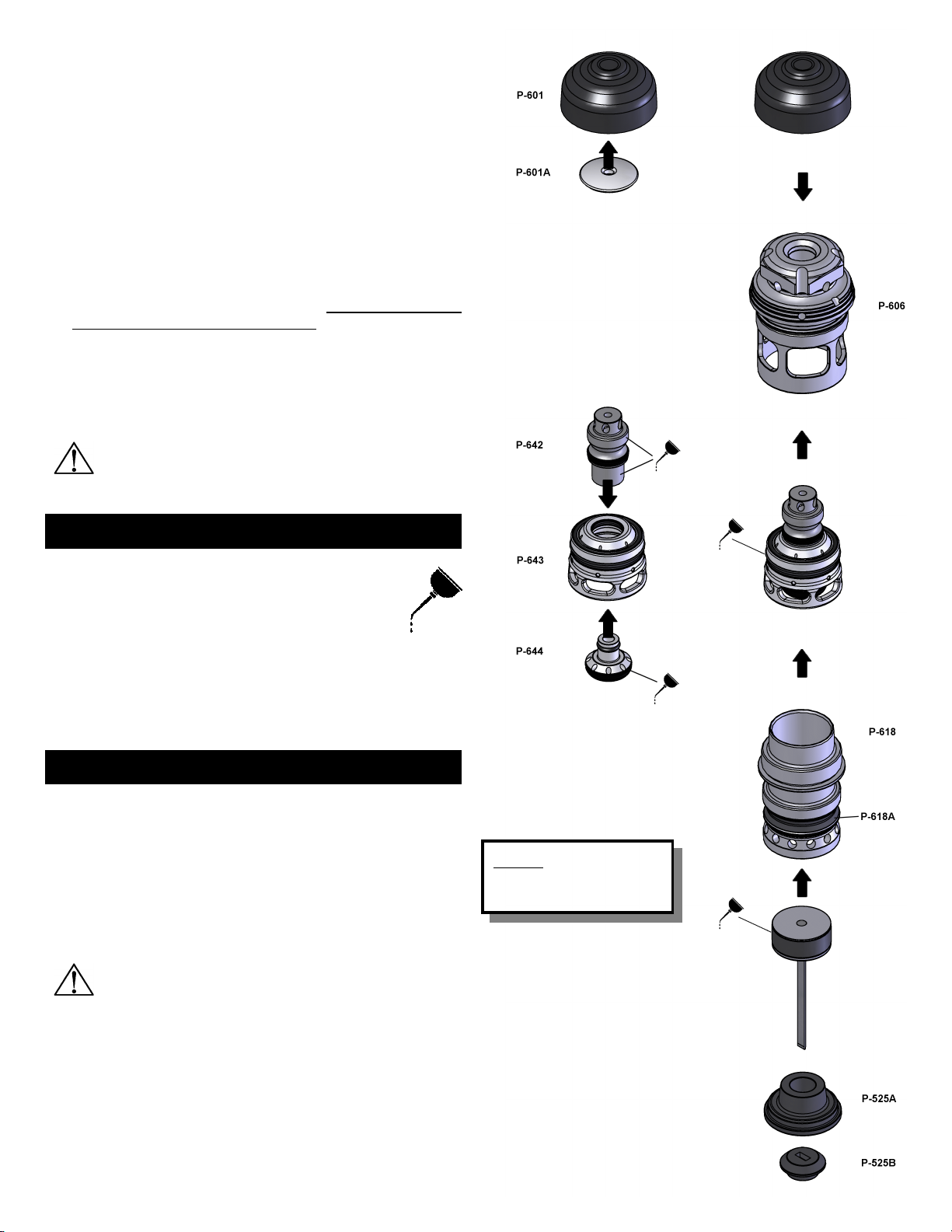
The P250Aisbuilt around the
Primpact valveengine, a
breakthrough technologyfor
pneumatictools. Primpact main
featuresare:
•short noseand compact valvedesign withan all-
around striking surface
•high-speed action and fewmoving parts, fora
powerful yet soft strokeand increased precision.
•reciprocal striking systemthat regulatesthe depthof
penetration independentlyfromthe mallet impact
•finelythreaded screw-in cartridge assembly
Forbestresult, onlyPRIMATECH fasteners should be used.Read
carefullytheseinstructionsbeforeoperatingthistool.Itisimportant
tounderstand warnings/cautionsand the safetymeasuresto
ensuresafeuseof thistool.
Additional information isavailable directlyfromthe manufacturer:
1135 Jérémie-Fortin, Québec, QC
Canada, G1J1R8
Phone:1(800)363-1962 or1(418)522-7744
Fax:1(418)522-7466
email: support@primatech.ca
web: www.primatech.ca/support
SAFETYMEASURES
Theseimportantguidelinesshould alwaysbe followed towork
safelywiththe PRIMATECH pneumatictool model P250A:
1.Read theseinstructionsthoroughlybeforeusing thistool and
keep it handyforreferenceif necessary.
2.Alwayskeep hands,feetorotherbodypartsawayfromthe
fastenerejection area.
3.Neveraimthe tool in anydirection otherthan the working
area.
4.Alwayscarryormanipulatethe tool byitshandle while the air
supplyhoseisconnected.
5.Neverhitthehead capofthe actuatorifthe plasticbaseisnot
sitting perfectlyon the working surface.
6.Neverleavethe tool laying downon itsside while the air
supplyhoseisconnected;the tool should alwaysbe left on
the floor, standing on itsplasticbase.
7.Do not alterorremovesafety.
8.Alwaysdisconnectthe airsupplyhosewhen the tool isnotin
useorwhen movetoanotherworkarea.
9.Neverserviceorrepairthe tool,clearobstructionsormake
adjustmentswhile the airsupplyhoseisconnected.
10.Onlycompressedairshould beused topowerthistool;donot
exceed 110 psi(7.6bar).
11.Neveruseoxygen oranyothercompressed gasasapower
sourceforthistool.
12.AlwayswearOSHA-required Z-87 safetyglasseswithside
shields.
13.Alwayswearproperearand feetprotection while the air
supplyhoseisconnected.
14.Alwaysremovefasteners fromthe feederchannel before
servicing tool.
DO NOTREMOVE ORALTERSAFETY.NEVERDEPRESS THE
SAFETY CONTACTWITHYOUR HANDS WHENTOOLIS
CONNECTEDTO AIRSUPPLY.EXTREME CAUTIONIS
ADVISEDWHENUSING THIS TOOL.
CONNECTION & AIR SUPPLYSYSTEM
Toensuremaximumperformanceand efficiency,and alsoa
minimumofcare,thePRIMATECH pneumatictoolrequiresclean,dry
air. It isnecessarytouseafilterand apressureregulator.
Thistool needsadetachable male couplerwith3/8"NPTmale
treads.The useofa3/8"(1cm) diameterairsupplyhoseis
recommended.Asmallerhoseorahoselongerthan 50'(15 m)
could causeapressuredrop when the tool isactivated repeatedly.
ALWAYS USE AFREE-FLOWCONNECTIONFORTHE
COMPRESSEDAIRSUPPLY TO PREVENTTHATTHE TOOL
STAYS CHARGEDAFTERDISCONNECTING THE AIRSUPPLY
HOSE.
UNLOADTOOLBEFORE CONNECTING AIRTO PREVENT
ACCIDENTALDISCHARGE.
AFTERMOVING TOOLTO ADIFFERENTWORK AREA,OR
AFTERANY MAINTENANCE TO THE TOOL,ALWAYS ENSURE
PROPEROPERATIONBY ACTUATING TOOLSEVERALTIMES
WITHOUTFASTENERS OVERTHE SUBFLOORING .
Dirt, dust, and otherparticlesin the airsupplycan causesluggish
operationorprematurewearofmanycomponentsofthetool.Drain
waterfromthe compressortankregularly.The compressorstart-
stop limitsshould be settodeliveran airpressureofatleast
100 psi(7bar) atall time.Consultthe compressormanual or
dealerforinstructionson howtomakethisadjustment.
At80 psi(5.5bar) and 100 hitsperminute,thistool consumes
approximately4.7cu.ft (130 )ofairperminuteat70°F(21°C).
Higherairpressurewill increasethe consumption ofcompressed
air.
Thistool isdesigned tobe operated withacompressed air
pressureof80 to100 psi(5.5-7.0bar).Anairpressureof90 psi
(6.2bar) isadequateformostsituations,although occasionally, a
higherpressurecould be necessary,forexample tousethe tool
withdifferentspeciesofharderwood.Inthesemoredifficultcases,
the compressed airpressurecan be increased up to100 psi
(7.0bar).It isveryimportantnottoexceed thismaximumpressure
toprevent leaks, prematurewearordamagestothe tool.

Checkthe compressed airsupplyhosebeforeconnecting to
ensurethattheyarefree fromdirtorparticlesthatcan alterthe
performanceofthe tool.Payspecial attention toanyairleaks.Do
notuseacompressed airpressurehigherthan 110 psi(7.6bar).
Higherpressurecan causeprematurewearordamage tocertain
components.Afterassembly,checkall the connectionstoprevent
the leaksand tohavemaximumefficiency.
TO PREVENTACCIDENTALDAMAGE TO THE FINISHED
SURFACE OFTHE INSTALLEDFLOOR,RESTTHE TOOLONTO
THE SUBFLOORING WHENCONNECTING AIR,LOADING TOOL
ORPERFORMING ANY MAINTENANCE TO THE TOOL.
LOADING THETOOL
Several feederchannel configurationsareavailable forthistool.
Conventionalfeederchannelscomewithan integratedpusherthat
mustbe engaged behind the nailsatall time.Forthose,simply
insertarowofPRIMATECH's cleatsorstaplesinside the feeder
channel and pull backon the plastictab gentlyuntil itengages
behind it. Torelease,simplysqueezethe tab withyourthumband
indexandallowthespring torecoil slowly.The clip mustbe
released slowlytoprevent damage.
Toolsfitted withthe LOADXTEND (Patent
Pending)automaticfeederchannelhold&feed
200 nailsin an assemblyno longerthan aconventional one.Its
exclusivepusherlocksintoapre-armed position,allowing nailsto
be fed bygravityuntil itautomaticallyengagesbehind.Withonly
one strip ofnails,the LOADXTEND feederchannel isoperated in the
samewaybysimplypullingthe pushertoengage itbehind the
nails.
The real time-saving featureistoallowatanytimetofill oradd
nailsintothe LOADXTEND feederchannel,up to200 nails.Simply
pull the pusherall the wayuntil it locksintoitspre-armed position
and ensurethatthe nailsarefullypushed intothe nail ejection
area.Thepusherwillautomaticallyengagebehind thenailsasthey
pass-by.
USE ONLY THE TYPE OFFASTENERS IDENTIFIEDONTHE
FEEDERCHANNEL.THE USE OFANY OTHERTYPE OF
FASTENERS WILL DAMAGE THE TOOL.
OPERATION
Unload tool and restitontothe subflooring,Connectthe hoseand
cycle tool onceortwicewithoutfastener.Afterloading the tool,the
tool isreadyforuse.
Useonlythe 2.5lbs(1.1kg)hammersupplied withthe tool.The
useofothertype ofhammers mayaffectperformance.The rubber
faceofthe hammercan be used withcaretohelp position the
boards.
Withthe flooring firmlyin place,position the tool
ontothe flooring,withthe resting blockP-534
againstthe tongue.Applydownwardpressureto
ensureproperseating ofthe fastener.Strikethe
head cap P-601 withthe hammertoactivatethe
tool, Use onlythe RUBBERFACE ofthehammer
toactivatethetool. Using thesteelend will
damagethetooland void thewarranty. Ifwood
isslightlytwisted,hitting the tool withmoreforce
will assistin pulling the boardup snugly. NEVER strikethe head cap
when the tool isnot sitting on the working surface.
OPERATING THE TOOLWHENTHE SAFETY CONTACTIS NOT
FULLY DEPRESSEDWILL CAUSE PREMATURE WEAROR
DAMAGE TO THE DRIVING BLADE,PISTONAND CYLINDER.
Eyeprotection isrecommended and should be
wornbytheoperatorand otherin working area.
Accidental ejection offasteners orwood debris
could causesevereeyeinjury.
Insomeenvironments, earprotection might be
required, asworking condition mayinclude
exposuretohigh noiselevelswhichlead to
hearing damage.
Wearingsafetybootsand safetyhatisalsohighly
recommended.
NOTE:All the personal protection equipments
must meet national standards.
Beitraw,factoryfinished orengineered,hardwood isanatural
material subjecttovariousfactors,suchashumidity,subflooring,
installation procedure,type oftools,fasteners, etc.Installershould
alwaysensureoptimal surfacepreparation,complywithall
manufacturer's recommendationsand conductapre-installation
test priorbeginning anyinstallation.
BEFORE STARTING ANINSTALLATION,FASTENDOWNFEW
BOARDS TO ASCERTAINTHATYOUARE USING THE RIGHT
FASTENERAND THATTHE TOOLIS PROPERLY ADJUSTED.
ADJUSTING FOR HARDWOOD THICKNESS
The P250Apneumatictool isfitted withafullyadjustableplastic
basedesigned topreventcontactwiththe top edge ofthe flooring.
It isimportanttoadjustthe tool tofitthe flooring priorany
installation.The P250Aalsofeaturesaresting blockwhichprevent
damage tothe top edge ofthe flooring bypositioning the tool
againstthe tongue,preventing the gate/footassemblyfrom
contacting the board.
Step 1: adjusting the baseforflooring thickness:
•Using the supplied Allen wrench,loosen butdo notremove
screws(A); twoon eachside of the tool.
•Withthe tool in an upside downposition,placeashortpiece
of flooring against the gate/foot assembly(P-429).
•Engagethe Allenwrenchin knob(B) asshown;rotatetomove
the baseup ordown. Notethatknob (B) hasarotation range
ofonlyabout1/2turn.Do notapplyforcewhen alimitis

reached.
•Adjustthe heightofthe plasticbasetoobtain asmall gap
betweenthe gate/footassemblyandthe topside ofthetongue
ofthe sample board.Agap of1/32"should be adequatefor
most situations.
•Tighten bothscrews(A).
Step 2: adjusting the resting blockforthe widthof the tongue:
•Using the Allen wrench,loosen byabout1/2turn do not
removethe twoscrews(C).
•Withthe shortpieceofflooring still againstthe gate/foot
assembly,adjustthe gap between the resting blockand the
tongue withscrew(D).Asmall gap of1/32"should be
adequateformost situations.
•Tighten bothscrews(C).
•Ensurethatscrew(D)isslightlytighten.Do notapplyforceon
screw(D)oncescrews(C)aretighten.
Aftercompleting the adjustmentprocedure,proceedwiththe
installationoffewboards.Carefullycheckfortheproperpositioning
ofthe fastenerontothe board.Checkagain afterfewmorerowsto
insurethatallpartsaresecured inplace.Tool mayloseadjustment
overtimeif thisprocedureisnot strictlyfollowed.
BEFORE STARTING ANINSTALLATION,FASTENDOWNFEW
BOARDS TO ASCERTAINTHATYOUARE USING THE RIGHT
TOOLAND FASTENER.
PREVENTIVE MAINTENANCE
Thistoolrequiresminimallubrication.Useonlydetergent-
freeoilsuchasPrimatechP-090.Fewdropsofoil weekly
in the airinletissufficient. Othertypesoflubricantmay
degrade the seals.
Checkperiodicallytomakesurethatall screwsaretight. Pay
particularattentiontothetwoscrewsholding thefeederchannelas
well asthe screwsand nutson the feederchannel assemblywho
mightloosen up overtime.The useofan mediumstrength
adhesivesealant isrecommended.
MAINTENANCE& REPAIR
Mostadjustmentstothe tool can bemadewiththe 3/16"Allen
wrenchsupplied withthe tool.
Disassemblyofthe tool mustbe done in aclean environment.
Somepartscan be easilydamaged ifdisassembled withimproper
toolsorbyinadequatemethods.Maintenanceshould onlybe
performed bytrained personnel.Useonlygenuine PRIMATECH
replacement parts.
TO PREVENTINJURY,ALWAYS DISCONNECTTHE AIR
SUPPLY HOSE WHENSERVICING ORDISASSEMBLING THE
TOOL.
When servicing the tool,do nottwistorforceanyparts.Damage
mayresultfromsuchabuse.If partsdo notcomelooseeasily,
contact yourPRIMATECH distributorformoreinformation.
When opening the tool formaintenance,alwaysclean all
componentsofdirt, grit, orparticles.Inspectthe tool carefullyfor
broken partsorexcessivewear,and replaceifnecessary.When
ordering parts,be suretospecifythe rightpartnumber,and also
the tool serial number.
NEVERapplythreadlocker
oradhesiveontocylinder
orhead threads.

Complete'cartridge'assembly
AFTERANY MAINTENANCE TO THE TOOL,REMOVE ALL
FASTENERS BEFORE CONNECTING AIRAND ACTUATE THE
TOOLREPEATEDLY OVERAPIECE OFWOODOR
SUBFLOORING TO INSURE PROPEROPERATION.
ASSEMBLING THEVALVE
All pneumaticcomponentsrequired arepacked in acartridge
assemblywhichissimplyinserted intothe tool.Thissection
describeshowtoassembleallthecomponentstogether.However,
itisusuallynotnecessarytocompletelydisassemble the valve.
Refertonextsection,"CLEANINGTHEVALVE"formoreinformation
on howtoopen the tool forregularmaintenance.The following
procedureassumesthatthegate/footassembly(P-429)along with
the resting blockP-534 arealreadyinstalled.Refertothe
"ReplacementParts" document foracompletelist and schematic
of the tool.
1.It isusuallynotrequired toseparatethe head diskP-601A
fromthe head cap P-601.If necessary,insertthe head disk
firmlyin placeintothe head cap.
2.Alignthe headcap P-601withthe twopinsonthe headP-606
and snap the cap in place.It isusuallynotrequired toremove
the head cap fromthe head.
3.Checkthe condition ofall ringsand sealson the actuator
P-642, actuatorcap P-644 and main valveP-643.
4.LightlylubricateactuatorP-642 asshownand insertitinto
valveP-643.
5.Lightlylubricatethe permanentseal ofactuatorcap P-644 as
shown.Do not lubricatethe small o-ring (see partP-644C on
schematic).Insertthe actuatorcap asshownand forcibly
snap it intothe actuatorP-642
6.Insertthevalvesub-assemblycompletelyintotheheadP-606.
7.Screwthe cylindercompletelyontothe head bodyP-606and
tighten firmlybyhand.Takecarenotdo damage the threads.
Pull downthe valveP-643 tosit it ontothe cylinder.
8.Checkthatthe band-valveP-618Aisproperlyinstalled onto
the main cylinderP-618.
ALWAYS CHECK THATTHE CYLINDERIS COMPLETELY
SCREW-ONTHE HEADBEFORE INSERTING THE ASSEMBLY
INTO THE TOOL.THE CYLINDERWILL LOOSEN-UP WHEN
THE CARTRIDGE IS TAKEN-OFF THE TOOL.
ALWAYS PULL DOWNTHE VALVE AGAINSTTHE CYLINDER
BEFORE INSERTING THE HEADASSEMBLY.
9.Checkthatthe piston sub-assembly,including ringsand
drivingblade,isslidingeasilyintothe cylinderP-618.Itshould
offersomeresistance,butifitmovestoo easily,itmaybe
required toreplacethe piston wear-ring P-622A.
10.Insertthe seal bushing P-525Bin the lowersection ofmain
bodyP-606 and engage itontothe upperportion ofthe
gate/footassembly(P-429).Aflatscrewdrivercan help
locationthe sealbushing correctly.Usethewooden handleof
the hammertotap the seal bushing completelyin place. It is
usuallynotnecessarytopull-outthe seal bushing P-525Bfor
maintenance.
11.Withthe tool in the uprightposition,pushthe bumperP-525A
in place,indexed ontothe seal bushing P-525Band usethe
wooden handle toseat the bumperin position.
12.Insertthe piston sub-assemblyintothe main bodyP-616 and
engage the driving blade P-423 in the seal bushing opening.
Depress the safetycontactP-562 toensurethatthe driving
blade hasengaged the gate/foot assemblyguiding channel.
13.Loosen the lockP-616D and insertthe whole head assembly
intothe main bodyP-616; the main cylinderP-618 engaging
ontothe piston assembly.Screwthe head assembly
completely.Takecarenotdodamagethethreads.Rotatethe
headlockP-616D clockwiseandtighten withmoderateforce.
NEVERLOCK THE HEADORCYLINDERINAVISE.IFMORE
TORQUE IS NECESSARY,INSERTTHE LONG ARMOFAN
ALLENKEY INTO ONE OFTHE SIDE HOLES OFTHE HEAD
AND/ORAROUND SCREWDRIVERTHROUGHTHE LARGE
HOLES OFTHE CYLINDER.ALWAYS (UN)TIGHTENBY HAND.
NEVER APPLY THREADLOCKERORADHESIVE ONTO
CYLINDERORHEADTHREADS.
ITIS MOSTIMPORTANTTHATTHE MAINCYLINDERBE FULLY
SCREWED &TIGHTENEDONTO THE HEADASSEMBLY
BEFORE BEING INSERTEDINTO THE MAINBODY.
AFTERREASSEMBLY,ALWAYS ACTUATE THE TOOL
REPEATEDLY WITHOUT FASTENERSAGAINSTAPIECE OF
WOODTO INSURE PROPEROPERATION.
Thistool featuresahead lockto
maintain firmlyin placethe head
assemblyduring operation.Before
inserting the head assembly,ensure
thatthe P-616D lockisfree toswivel
and rotateitawayfromthe head
opening.Afterinserting the head
assemblyin place,rotatetheP-616D
lockand tighten withthe Allen key
using moderateforce.
Toremovethe head assembly,simplyunscrewthe P-616D screw
¼turnand rotateit counter-clockwise.
CLEANING THEVALVE
If the tool becomessluggishordoesnotsetthe fastener,itmay
indicateexcessivedirt, dust, otherparticles, oreven water, in the
head assembly,therebyimpedingthe cycling ofthe valve.The first
step in troubleshooting istoclean up the head assembly.
1.Loosen (¼ turn)the head lockP-616D.

2.Unscrewthe head assemblyP-606 and takeitoutofthe tool.
The long arm ofaAllen wrenchmaybe inserted intoone of
hole at the baseofhead P-606 tohelp unlockthe assembly.
3.Pull-outthe piston assemblyand unscrewthe cylinderP-618.
Perform avisual inspection ofthe driving blade P-423,the
wear-ringP-622Aand theinnersurfaceofthe cylinderP-618.
Do not removethe driving blade fromthe piston.
4.Pull-outthe valveassemblyP-643 and perform avisual
inspection ofall rings.Checkthatthe actuatorassembly
P-642/P-644 issliding easilyon valveP-643.Clean and
lubricatelightly.It isusuallynotnecessarytotakeapartthe
actuatorassembly.
5.If necessary,actuatorcap P-644 maybe unsnaped from
actuatorP-642 byinserting the long arm ofanAllen wrench
through the hole on top ofthe actuatorand using ahammer
withmoderateforcetoget the partsapart.
6.Clean the inside wall ofthe head bodyP-606 andlubricate
lightlywithanon-detergentoil.Checkthe o-ring P-606A.It is
generallynot necessarytoremovethe head cap P-601.
REPLACING THEDRIVING BLADE
The driving blade issold separatelyorsupplied asacomplete
subassemblywiththe piston P-622.
1.Unscrewthe head assemblyP-606 and takeitoutofthe tool.
2.Pull-outthe piston assemblyfromthe cylinder.Removeany
debrisand assess condition ofcylinderP-618.If marked or
grouged,useafine sand papertosmoothoutwalls.The
piston P-622 mustbe allowed tomovewithoutrestriction.
Skip tostep(7)ifyou arereplacing withapiston/driving blade
subassembly.
3.Lockthe piston in avise,using
aragtopreventscoring.
Alwaysusethetop andbottom
facestosecurethe piston in
place.
4.Removethe broken driver
using a1/2" closewrench.
5.Putone drop ofmedium
strengthadhesivesealantontothe threadsofthe piston
P-622.
6.Insertthe P-622C lockwasherand screwthe newdriving
blade ontothe piston P-622.Tighten veryhard (140 lbin
minimum).Makesurethatthe lockwasherP-622C is
completelyflattened.
Note: select the appropriatedriving blade:
•useP-423 driving blade forthe "L" or"T" bailers
•useP-237 driving blade forstaplerconfiguration
7.Insertthe piston sub-assemblyintothe main bodyP-616 and
engage the driving blade P-423 in the seal bushing opening.
Depress the safetycontactP-562 toensurethatthe driving
blade hasengaged the gate/foot assemblyguiding channel.
8.TightenthecylinderP-618 ontotheheadP-606andfollowthe
proceduretocompletethe assemblyof the head.
INSTALLING THESAFETY
You shouldn'tneed toremovethe safetystop mechanism unless
the element P-561 do not swivel orhasabroken tip.
1.Assemble togetherpartsP-561,Q-061A,Q-061C and
Q-061D.
2.Insert the short end of P-561Basshown.
3.Puttwodropsofadhesivesealantontothe thread area of
Q-061C,nearitscylindrical end.Makesureno sealantis
retained on the end orexteriorwall.
4.Insert the assemblyintothe hole in the tool bodyasshown.
5.Tight togetherwithscrewP-153A, holding Q-061C.
INSTALLING THEBASE ASSEMBLY
The plasticbasecan beinstalled orremoved withoutthe need of
atool.
1.First, insertconnecting stem
P-561BtothesafetycontactP-562.
2.Lift the safetycontactandfully
slide-in the plasticbaseP-533onto
the bracketsP-535A&B.
3.The safetycontactshould simply
drop intoplace.Insertthe locking
rod P-562 until itsnaps.It should
engage the safetycontact.

TROUBLESHOOTING
Thissectionwillhelptodiagnosecommonproblemsandwillgive
suggestionstosolvethem.Consultouron-lineTechnicalSupport
siteat www.primatech.ca/support forupdated documentsand
moretips.
TO PREVENTINJURY,ALWAYS DISCONNECT THE
AIR SUPPLY HOSE WHENADJUSTING,SERVICING OR
DISASSEMBLING THE TOOL.
FIRST:CHECK THE COMPRESSEDAIRSUPPLY
Manyofproblems comefromafaultyorinadequate
compressed airsupplysystem. Beforeattempting torepair
the tool, the following pointsshould be checked:
a)checkthe pressureatthe outputofthe compressor;
adjust to80-100 psi(5.5-7.0bar) asrequired
b)checkthe tankpressureof the compressor&adjust the
start/stop limits
c)checkthe airdeliverysystem;a3/8"hoseis
recommended
d)usefewertoolssimultaneously;do notexceed the
capacityof the compressororof the deliverysystem
e)drain waterfromthe compressor
SECOND:CHECK FORAIRLEAKS
Atrest, thistool should nothaveanyairleak.Before
attempting torepairthe tool and replaceparts,checkthe
following:
a)CheckringsP-606A,P-516B,P-009,P-543Aand
P-543D; replaceif necessary
b)The top edge ofmain cylinderP-618should be free of
dents.
c)Clean &lubricatethe head assembly;re-assemble the
head assemblycarefully
d)Checkinteriorof head P-606 forscratches
HEADASSEMBLYLOOSENS UP DURING OPERATION
Removethe head assemblyand insurethatthe cylinderis
fullyscrewed on.Re-insertthe head assemblyin placeand
insurethat the head lockP-616D iscorrectlyin place.
TOOL DOES NOTDRIVE FASTENERS
a)Checkthat therearefasteners in the feederchannel
b)Makesurethe feederclip isengaged behind the
fasteners
c)Checkthe frontend ofthe feederchannel forburrsor
damages
d)Checkthe safetymechanism
e)Checkifthe driverisstuckin downposition (see 6
below)
f)Checkforobstruction in the fastenerejection area
FASTENERS ARE NOTSETCOMPLETELY
a)First, verifyairsupply(see 1above)
b)Clean tool and lubricatetool;particularlythe head
assembly
c)Increaseairpressurewhen working withharderwoods;
do not exceed 110 psi(7.6bar)
d)Checkthe driving blade forbroken end
e)Checkpiston wear-ring P-622A;replaceifpiston is
sliding toeasily
f)Checkseal bushing P-525B
g)Checkthe adjustmentofthe baseand ensurethe tool is
well seated on the floorwhile ejecting
TOOL DOES NOTACTIVATE
a)Checkthe airsupply
b)Inspectthe head assemblyand checkall seals;
reassemble carefully
DRIVING BLADE DOES NOTRETURN
a)Checkforjammed fastenerorobstruction
b)Checkgate/footand end offeederchannel fordamages
orburrs.
c)Checkthe driving blade P-423
d)Inspect the head assemblyand checkall seals; clean &
lubricate.
e)Checkband-valveP-618A.
f)CheckthatthebumperP-525Aand sealbushingP-525B
arein place.
BROKENORWORN DRIVING BLADE
Replacethe driving blade P-423.Failuretofollowthe
instructionscarefullywill resultin repeated breakage of the
driving blade.
POORFEEDORTOOLJAMMING
a)Makesurethe feederclip engagesbehind the fasteners
b)Checkthe gate/foot assemblyfordamagesorwear
c)Check the frontend ofthe feederchannel forburrs or
damages
OTHERPROBLEMS
Contact Primatech:
byphone1(800)363-1962
1(418)522-7744
byemail support@primatech.ca
consult ouron-line Technical Support siteat
http://www.primatech.ca/support

TOOL WARRANTYAND LIMITATIONS
Primatechwarrantsthatnewlypurchasedfastening tools,parts
and accessorieswill be free fromdefectsin materialand
workmanship (excluding wearparts)forthe period shown
below,afterthe dateofpurchasebythe original useras
evidenced byavaluable purchaseinvoice.
ONE-YEARLIMITEDWARRANTYwillapplytoallparts,except
thosesubjected tonormal wear
SEVEN-YEAREXTENDEDLIMITEDWARRANTYcovers tool
casing.
WARRANTYSTATEMENT
Primatech‘ssole liabilityhereunderwill be toreplaceanypart
oraccessorywhichprovestobe defectivewithin the specific
timeperiod.Anyreplacementpartoraccessoriesprovided in
accordancewiththiswarrantywill carryawarrantyforthe
balanceofthe period ofwarrantyapplicable tothe partit
replaces.Whenrepairorreplacementofpartortoolisrequired,
the completetool orpart(s) mustbe returned toPrimatechorat
suchauthorized warrantyservicepointofPrimatech,
transportation prepaid,withacopyofproofofpurchase
evidencing that the part ortool iswithin the warrantyperiod.
Thiswarrantyisvoid astoanytool whichhasbeen subjected
tomisuse,abuse, accidental orintentional damage, used with
fasteners notmeeting Primatechspecifications,sizeorquality,
improperlymaintained,repaired withotherthan genuine
Primatechreplacementparts,damaged in transitorhandling,
orwhich,in Primatech‘ssole opinion,hasbeen altered,
modified orrepaired in awaythataffectsordetractsfromthe
performanceof the tool.
PRIMATECH MAKESNOWARRANTY,EXPRESSEDOR
IMPLIED,RELATINGTOMERCHANTABILITY,FITNESS,OR
OTHERWISE,EXCEPTAS STATEDABOVE,and primatech
‘sliabilityAS STATEDABOVE AND AS ASSUMEDABOVE is
in lieu ofall otherwarrantiesarising outof, orin connection
with,the useand performanceofthe tool,excepttothe extent
otherwiseprovided forbyapplicable law.
PRIMATECH SHALL INNOEVENTBE LIABLEFORANY
DIRECT,INDIRECT,ORCONSEQUENTIALDAMAGES
WHICH MAYARISE FROMLOSS OF ANTICIPATED
PROFITSORPRODUCTION,SPOILAGEOF MATERIALS,
INCREASEDCOSTOF OPERATION,OROTHERWISE.Any
liability,ifany,connectedwiththe useofthetool shallterminate
upon the expiration of the warrantyperiod specified above.
Other manuals for P250A
1
Table of contents
Other primatech Tools manuals