Primes FocusMonitor FM+ User manual

FocusMonitor FM+
LaserDiagnosticsSoftware LDS
35,0(6
Original Instructions
Revision 08 EN - 08/2023


FocusMonitor FM+ 35,0(6
3
Revision 08 EN - 08/2023
IMPORTANT!
READ CAREFULLY BEFORE USE.
KEEP FOR FUTURE USE.

FocusMonitor FM+
35,0(
6
4Revision 08 EN - 08/2023
Inhaltsverzeichnis
1 Basic safety notes 7
2 Icons and conventions 10
3 About this operating manual 11
4 System description 12
4.1 Measuring principle .................................................................................................................13
4.2 Status Display .........................................................................................................................13
4.3 Explanation of the product safety labels ..................................................................................14
4.4 Scope of delivery and accessories ..........................................................................................15
5 Transport and storage 15
6 Installation and settings on the PC 16
6.1 Install LaserDiagnosticsSoftware LDS......................................................................................16
6.2 Set IP address of PC...............................................................................................................16
7 Mounting 17
7.1 Conditions at the installation site .............................................................................................17
7.2 Installation in the laser system .................................................................................................17
7.2.1 Prepare mounting .....................................................................................................17
7.2.2 Possible mounting positions......................................................................................18
7.2.3 Align the device ........................................................................................................19
7.2.4 Mount the device ......................................................................................................22
7.2.5 Connecting a FM+ to a laser power meter ................................................................23
7.3 Removal from the laser system................................................................................................24
8 Connections 24
8.1 Overview of the connections ...................................................................................................24
8.2 Power supply ..........................................................................................................................25
8.3 Ethernet ..................................................................................................................................25
8.4 PRIMES bus RS485................................................................................................................25
8.5 Inert gas connection................................................................................................................26
9 Measuring with the LaserDiagnosticsSoftware LDS 27
9.1 Warning messages..................................................................................................................27
9.2 Establish measurement readiness ...........................................................................................28
9.3 Connect/disconnect the device to the LDS .............................................................................29
9.3.1 Switch on the device and connect it to the LDS........................................................29
9.3.2 Changing the IP address of a connected device .......................................................30
9.3.3 Disconnect device from the LDS and switch off ........................................................31
9.4 General information about working with the LDS .....................................................................32
9.4.1 Enter user-defined device name................................................................................32
9.4.2 Open „Device control“ menu .....................................................................................32
9.4.3 Move vertical carrier for setup ...................................................................................33
9.4.4 Open a measuring mode ..........................................................................................34
9.4.5 Enter parameters and activate ..................................................................................35
9.4.6 Saving options ..........................................................................................................36
9.5 Settings that apply in all measuring modes..............................................................................37
9.5.1 Define locked area ....................................................................................................37
9.5.2 Move axes ................................................................................................................39
9.5.3 Entries for the measuring tip used.............................................................................40
9.5.4 Display device orientation..........................................................................................40
9.5.5 Rotating the measuring tip ........................................................................................41
9.5.6 Coordinate system for rotated measuring tip.............................................................42

FocusMonitor FM+ 35,0(6
5
Revision 08 EN - 08/2023
9.6 Device control .........................................................................................................................43
9.6.1 Settings ....................................................................................................................43
9.6.2 Advanced .................................................................................................................46
9.7 Linescan .................................................................................................................................48
9.7.1 Search laser beam automatically...............................................................................48
9.7.2 Adjust the measurement track manually....................................................................49
9.7.3 Start measurement ...................................................................................................50
9.7.4 Display measurement results.....................................................................................50
9.8 Single planes...........................................................................................................................51
9.8.1 Search laser beam automatically...............................................................................51
9.8.2 Adjust the measurement window manually................................................................52
9.8.3 Measure manual caustics with the single plane measurement mode .........................53
9.8.4 Start measurement ...................................................................................................54
9.8.5 Display measurement results.....................................................................................55
9.9 Monitor ...................................................................................................................................56
9.9.1 Search laser beam automatically...............................................................................56
9.9.2 Adjust the measurement window manually................................................................57
9.9.3 Start measurement ...................................................................................................58
9.9.4 Display measurement results.....................................................................................58
9.10 Manual Caustic .......................................................................................................................59
9.10.1 Start measurement ...................................................................................................59
9.10.2 Apply a caustic suggestion (optional) ........................................................................60
9.10.3 Display measurement results.....................................................................................60
9.11 Automatic Caustic...................................................................................................................61
9.11.1 Start measurement ...................................................................................................61
9.11.2 Display measurement results.....................................................................................62
9.12 Determining the tool center point (TCP) using the FM+............................................................63
9.12.1 Distance of the pinhole to the horizontal carrier .........................................................64
10 Troubleshooting 65
10.1 Messages in the LaserDiagnosticsSoftware LDS during measurement ....................................65
10.2 Connection error when using the LDS.....................................................................................66
10.3 Other errors.............................................................................................................................67
11 Maintenance and service 68
11.1 Maintenance intervals..............................................................................................................68
11.2 Cleaning..................................................................................................................................68
11.3 Check/replace the measuring tip.............................................................................................68
11.4 Replace detector.....................................................................................................................71
11.5 Selection of the measuring tip and the detector.......................................................................73
12 Measures for the product disposal 74
13 Declaration of conformity 75
14 Technical Data 76
15 Appendix 79
A GNU GPL license notice..........................................................................................................79
B Determine the speed of the measuring tip used.......................................................................79

FocusMonitor FM+
35,0(
6
6Revision 08 EN - 08/2023
PRIMES - the company
PRIMES is a manufacturer of measuring devices which are used to analyze laser beams. These devices are
employed for the diagnostics of high-power lasers ranging from CO2-, fiber- and solid-state lasers to diode
lasers. A wavelength range from infrared through to near UV is covered, offering a wide variety of measuring
devices to determine the following beam parameters:
• Laser power
• Beam dimensions and position of an unfocused beam
• Beam dimensions and position of a focused beam
• Beam quality factor M²
Development, production and calibration of the measuring devices is performed at PRIMES. This guarantees
optimum quality, excellent service, and a short reaction time, providing the basis for us to meet all of our
customers’ requirements quickly and reliably.
PRIMES GmbH
Max-Planck-Str. 2
64319 Pfungstadt
Germany
Tel +49 6157 9878-0
www.primes.de

FocusMonitor FM+ 35,0(6
7
Revision 08 EN - 08/2023
1 Basic safety notes
Intended use
The device has been designed exclusively for measurements in the beam of high-power lasers.
Use for any other purpose is considered as not intended and is strictly prohibited. Furthermore, intended use
requires that all information, instructions, safety notes and warning messages in this operating manual are
observed. The specifications given in chapter14 „Technical Data“ on page76 apply. Any given limit values
must be complied with.
If not used as intended, the device or the system in which the device is installed can be damaged or destroyed.
In addition, there is an increased risk to health and life. Only use the device in such a way that there is no risk of
injury.
This operating manual is an integral part of the device and must be kept in the immediate vicinity of the place
of use, accessible to personnel at all times.
Every person who is responsible for the installation, start-up or operation of the device must have read and
understood the operating manual and, in particular, the safety instructions.
If you still have questions after reading this operating manual, please contact PRIMES or your supplier for
your own safety.
Observing applicable safety regulations
Observe the safety-relevant laws, guidelines, standards and regulations in the current editions published by
the state, standardization organizations, professional associations, etc. In particular, observe the regulations
on laser safety and comply with their requirements.
FocusMonitor FM+
35,0(
6
8Revision 08 EN - 08/2023
Laser radiation warning
During the measurement the laser beam is reflected from the rotating measuring tip. This produces scattered
or directed reflection of the laser beam (laser class 4). Depending on the wavelength of the laser, the reflected
beam is usually invisible.
To avoid injury from the reflected laser beam, no one should be in the hazardous area where the measurement
is taking place. The hazardous area must be defined before operation of the FM+.
During operation of the device, the laser radiation must be fully absorbed after passing through the measurement
zone.
The radiation is not absorbed by the FocusMonitor itsself. A suitable absorber must be used for this purpose.
Suitable PRIMES laser power meters can be found in chapter7.2.5 „Connecting a FM+ to a laser power meter“
on page23.
When working with the device, people in the hazardous area must protect themselves by taking the following
protective measures.
Fig. 1.1: Risk of injury due to scattered or directed reflections of the laser beam

FocusMonitor FM+ 35,0(6
9
Revision 08 EN - 08/2023
Necessary safety measures
DANGER
Serious eye or skin injury due to laser radiation
The device measures direct laser radiation, but does not emit any radiation itself. However, during
the measurement the laser beam is reflected from the rotating measuring tip.
This produces scattered or directed reflection of the laser beam (laser class 4). Depending on the
wavelength of the laser, the reflected beam is usually invisible.
X
During a measurement, a safety distance of one meter to the device must be maintained even
when wearing safety goggles and safety clothing.
X
Protect yourself from direct and reflected laser radiation while working with the device by taking
the following measures:
• Wear safety goggles adapted to the power, power density, laser wavelength and operating mode of the
laser beam source in use.
• Wear suitable protective clothing or protective gloves if necessary.
• If possible, also protect yourself from direct laser radiation and scattered radiation by using separating
protective devices that block or attenuate the radiation.
• If the device is moved from its aligned position, increased scattered or directed reflection of the laser
beam occurs during measuring operation. Mount the device in such a way that it cannot be moved unin-
tentionally, e.g. by bumping or pulling the cables
• Install safety switches or emergency safety mechanisms that allow the laser to be switched off immediately.
• Use suitable beam guidance and beam absorber elements which do not emit any hazardous substances
when irradiated.
Employing qualified personnel
The device may only be operated by qualified personnel. The qualified personnel must have been instructed
in the installation and operation of the device and must have a basic understanding of working with high-
power lasers, beam guiding systems and focusing units.
Modifications and changes
The device may not be modified in terms of design or safety without the explicit consent of the manufacturer.
The same applies to unauthorized opening, dismantling and repair. The removal of covers is only permitted
within the scope of the intended use.
Liability disclaimer
Manufacturer and distributor exclude any liability for damages and injuries which are direct or indirect con-
sequences of using the device not as intended or modifying the device or the associated software without
authorization.

FocusMonitor FM+
35,0(
6
10 Revision 08 EN - 08/2023
2 Icons and conventions
Warning messages
The following icons and signal words indicate possible residual risks in the form of warnings:
DANGER
Means that death or serious physical injuries will occur if necessary safety precautions are not taken.
WARNING
Means that death or serious physical injuries may occur if necessary safety precautions are not taken.
CAUTION
Means that minor physical injury may occur if necessary safety precautions are not taken.
NOTICE
Means that property damage may occur if necessary safety precautions are not taken.
Product safety labels
The following icons are used on the device itself to indicate imperatives and possible dangers:
Read and understand the operating manual before using the device!
Labeling according to WEEE directive:
The device must not be disposed of with household waste, but in a separate WEEE collection
in an environmentally friendly way.
Hand injuries warning
General warning sign
FocusMonitor FM+ 35,0(6
11
Revision 08 EN - 08/2023
Further icons and conventions in this operating manual
Here you will find useful information and helpful tips.
XIndicates a single instruction.
If several of these instructions appear one below the other, the order in which they are executed is
irrelevant or they represent alternative courses of action.
1.
2.
...
A numbered list identifies a sequence of instructions that must be executed in the specified order.
Indicates the result of an action to explain processes that take place in the background.
Indicates an observation prompt to draw attention to visible feedback from the device or the software.
Observation prompts make it easier to check whether an instruction was executed successfully.
Often they also guide to the next instruction.
Points to a control element that is to be pressed/clicked.
Points to an element described in the text (for example an input field).
3 About this operating manual
This manual describes the installation and operation of the FocusMonitor FM+ and how to perform measure-
ments with the LaserDiagnosticsSoftware LDS version 3.0 or higher.
In this operating manual, the abbreviations FM+ and LDS are used below.
For measurement operation with a PC, the LDS must be installed on the PC. The LDS in the basic version is
included in the scope of delivery. PRIMES will also be happy to provide you with a current download link.
The software description includes a brief introduction on using the device for measurements. For a detailed
description of the software installation, file management and evaluation of the measurement data, please
refer to the separate instructions for the LDS.
This operating manual describes the software version valid at the time of printing. Since the LDS is
subject to continuous development, the supplied data medium may have a newer version number.
FocusMonitor FM+
35,0(
6
12 Revision 08 EN - 08/2023
4 System description
The FocusMonitor measures the beam properties of focused laser beams. In addition to the geometric dimensions
of the focused laser beam, the focus position in space, the beam parameter product as well as the beam quality
factor M² are determined
.
The laser beam is scanned along the x-axis with a rotating measuring tip. The integrated horizontal and vertical
carrier moves the measuring tip in the y-axis and z-axis respectively, so that the beam properties of the focused
laser beam can be measured spatially.
This enables the automatic measurement of complete caustics over a z-axis length of 120 mm. In addition,
the mechanical design allows upside down installation without additional components.
The FM+ works with the PRIMES LDS and is equipped with an Ethernet interface for fast and secure data
transfer.
When the FM+ is in operation, the laser radiation that has passed through the measuring zone must be completely
absorbed.
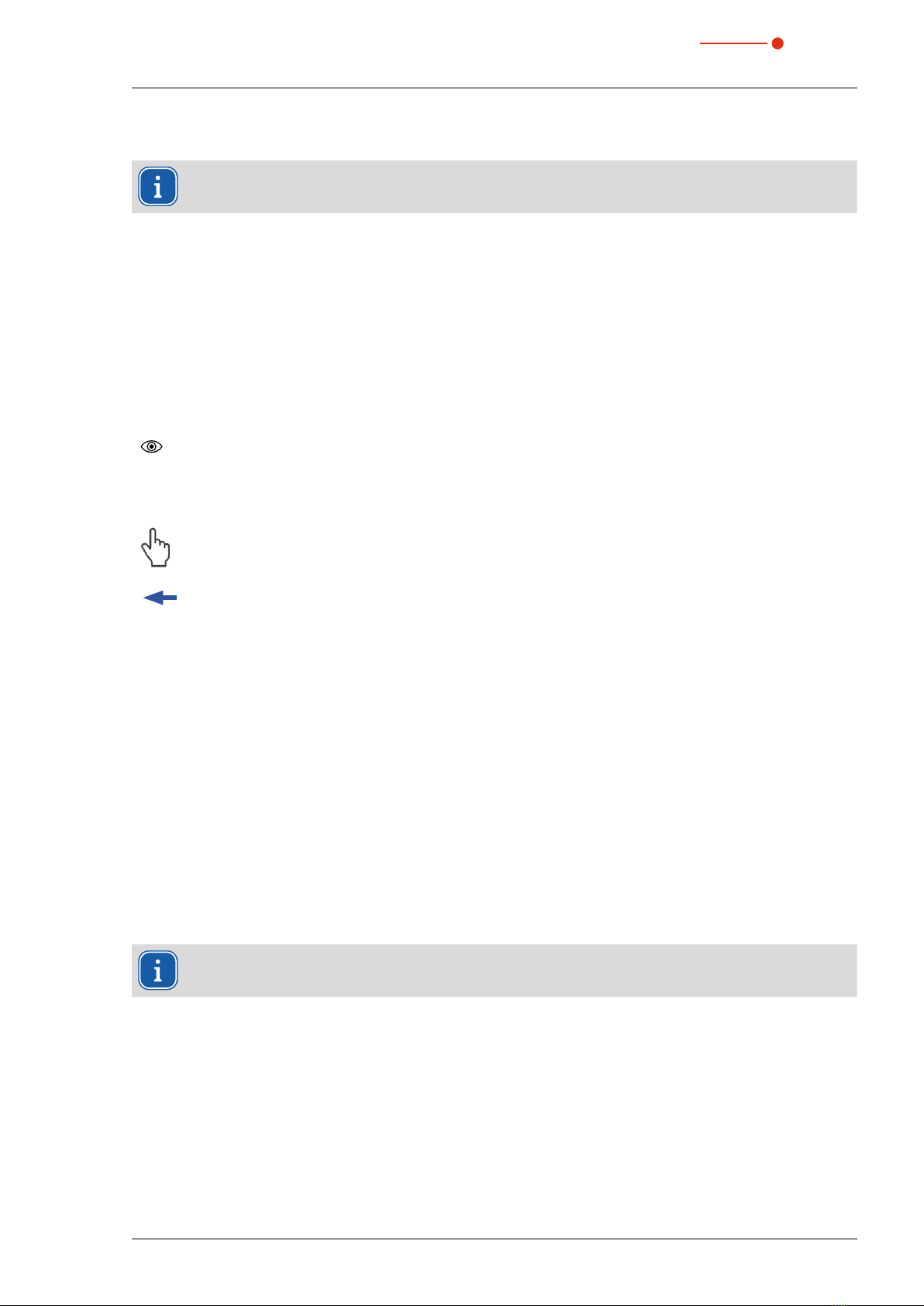
Fig. 4.1:
Vertical carrier
Horizontal carrier
z-axis
y-axis
Measuring tip
Detector
Main components FM+

FocusMonitor FM+ 35,0(6
13
Revision 08 EN - 08/2023
4.1 Measuring principle
The FM+ is an opto-mechanically scanning measuring system
The laser beam is scanned using a specialized measuring tip. A small pin hole (typical diameter: 25 μm) in
the measuring tip samples a small part of the laser beam. The sampled part of the laser beam is guided onto
a detector element
The detector is selected depending on the wavelength of the laser radiation to be measured. In this way,
different laser beam sources and systems can be measured by optimally selecting the measuring tip and the
associated detector.
The high angular velocity of the rotating measuring tip allows the analysis of high power densities.
Due to the dynamics of the analog-to-digital converters used, a very good signal-to-noise ratio is achieved.
Very low intensities as well as high peak intensities are recorded with equal precision.
This is one of the requirements for the automatic measurement of caustics in the near-focus range over at
least four Rayleigh lengths in accordance with ISO 11146.
Fig. 4.2:
Laser beam
x
z
y
Detector
Measuring tip
Optomechanical design FM+
4.2 Status Display
The status display consists of a light ring that uses different colors and static or rotating lights to indicate different
statuses of the FM+.
Color Lighting state Meaning
White The entire ring is lit The supply voltage is connected
Yellow Rotating light The measuring tip is rotating and the different rotational
speeds are indicated.
Red Rotating light The measuring tip rotating and the y-axis is moving.
The measurement is in progress, the different rotational
speeds are indicated.
Tab. 4.1: States of status display

FocusMonitor FM+
35,0(
6
14 Revision 08 EN - 08/2023
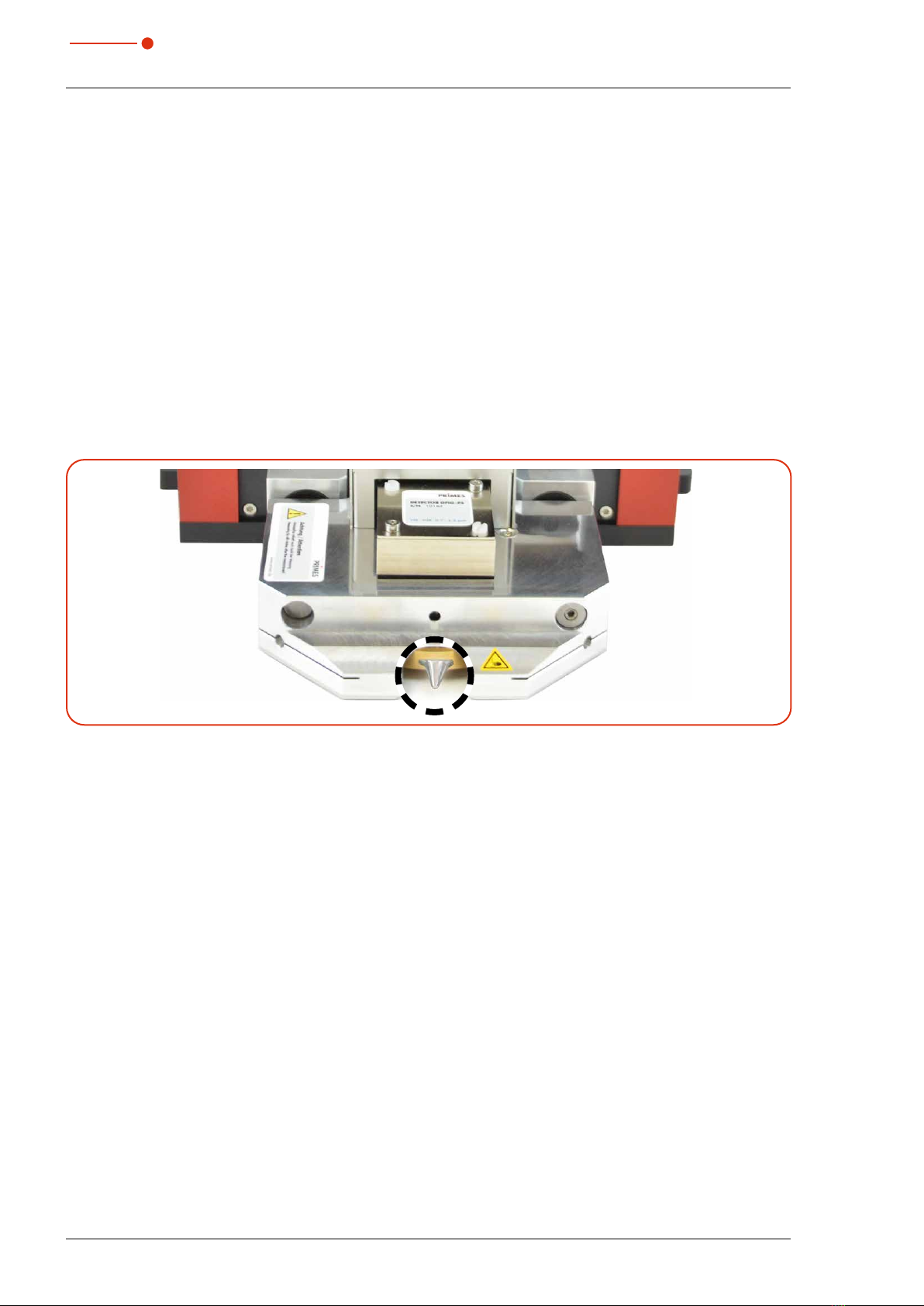
4.3 Explanation of the product safety labels
A potential hazard area for hand injuries is marked with a symbol “Hand injuries warning“ on the device.
Warning of hand injuries due to the rotating measuring tip
The measuring tip of the FM+ rotates at high speed during the measuring operation. Even after the measurement
or switching off the device, the measuring tip will continue to rotate for a certain period of time.
To avoid hand injury, do not reach into the device aperture when the measuring tip is rotating
.
If the rotating measuring tip hits an obstacle, the measuring tip will be damaged. In this case, the device
must be sent in for service. Therefore, no objects may be held in the beam path of the device.
After switching off the rotation or the device, wait for the measuring tip to come to a standstill (observe the
„Rotation“ status display), see chapter4.2 „Status Display“ on page13).
Fig. 4.3: Risk of injury due to a rotating measuring tip
Warning of hand injuries in the travel range of the carriers
The horizontal and vertical carrier can be moved relative to the housing. Do not reach into the movement
range of the carriers.
z-axis
y-axis
Fig. 4.4: Risk of injury in the travel range of the carriers

FocusMonitor FM+ 35,0(6
15
Revision 08 EN - 08/2023
4.4 Scope of delivery and accessories
The following parts are included in the scope of delivery:
• FM+
• PRIMES power supply
• Power cable
• Two alignment tools
• Patch cable Cat.5e, Cross-Over, 5m
• Patch cable Cat.5e, 5m
• PRIMES USB flash drive (PDF of operating manual, software, etc.)
• Operating manual FM+
• Operating manual LDS
The following accessories are available:
• Transport and storage case
• Measuring tip in a membrane box
• Detectors with box and screwdriver for mounting
5 Transport and storage
NOTICE
Damage/Destruction of the device
The device’s axes and carriers may be damaged if the device is subjected to hard shocks.
X
Handle the device carefully when transporting or installing it.
NOTICE
Damage/Destruction of the device
Imbalance of the rotational disc can damage the device.
X
Never operate the device without the measuring tip.
Remove measuring tip to avoid contamination
It is recommended to remove the measuring tip from the FM+ and place it in the supplied membrane box.
XRemove the measuring tip according to chapter11.3 „Check/replace the measuring tip“ on page68.
Transport and storage in the optional transport and storage case
In order for the device to fit into the optional transport and storage case, the carriers must be moved to the
park position before being switched off, see chapter9.3.3 „Disconnect device from the LDS and switch off“
on page31.
XOptionally switch the device off and on again. The carriers of the device move to the park position after
approx. 10 seconds.
A defined locked area when using a rotated measuring tip prevents the device from reaching the park position.
XRemove the locked area according to chapter9.5.1 „Define locked area“ on page37.
FocusMonitor FM+
35,0(
6
16 Revision 08 EN - 08/2023
6 Installation and settings on the PC
6.1 Install LaserDiagnosticsSoftware LDS
The basic version of LDS is included with the device. PRIMES will also be happy to provide you
with a link to download the current version. Please contact your sales partner or contact us by
email: [email protected]
1. Please ensure:
• System requirements are met.
• You have administrator rights.
2. Close all programs on your PC.
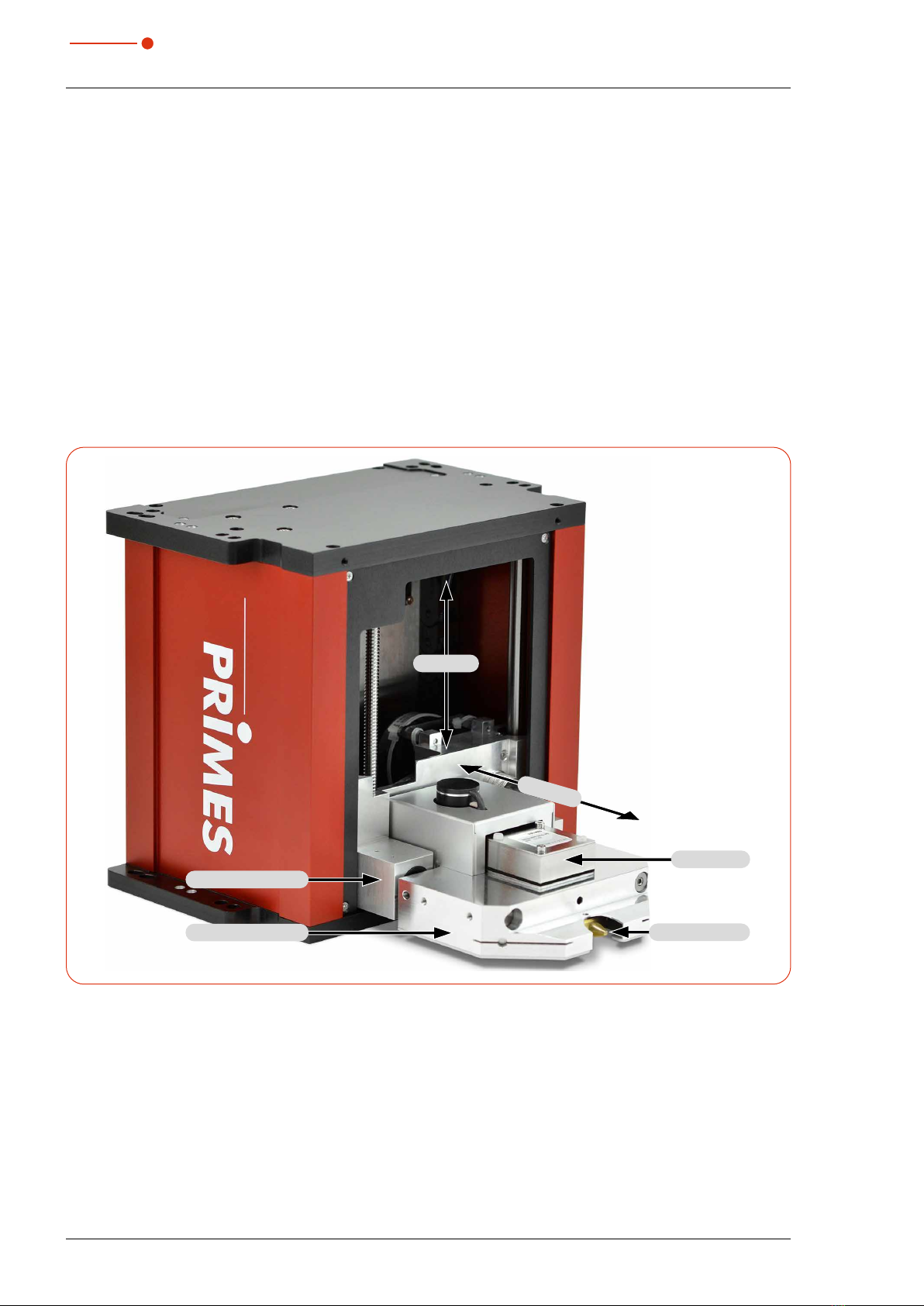
3. Insert the PRIMES thumb drive into
your PC and open the directory.
In the standard configuration, Windows
automatically opens the removable
storage device
.
System requirements:
• Intel Pentium Corei3 or better
• Windows 10 (64-bit version)
• At least 4GB RAM; 8GB RAM recommended
• Display resolution: Full HD (1920x 1080) at 100% scaling
• An Ethernet port for connecting the measuring device
4. Double-click the LDS_Setup exe file
to start the installation.
5. Follow the instructions on the screen.
If no other Iocation is specified, then
the main program LDS.exe
will be copied to the directory
C:\Programs\Primes\LaserDiag-
nosticsSoftware.
6.2 Set IP address of PC
The PC must be in the same IP address range as the PRIMES device.
Choose one of the following options to establish a connection between the PRIMES device and the PC.
The IP address of the PRIMES device can only be changed once this connection has been established
(see chapter chapter9.3.2 „Changing the IP address of a connected device“ on page30).
Integration of a PRIMES device into a network
Within the PRIMES device, the option DHCP (Dynamic Host Configuration Protocol) is activated by default.
The device obtains its IP address from the DHCP server.
Direct connection of a PRIMES device to a PC
In Windows > Control panel > Network and Sharing Center, assign an IP address to your PC that is in
the same address range as the PRIMES device (e.g. 192.168.116.xyz). The first three number blocks must
be identical, the last number block can be freely selected. The IP address should be entered by a system
administrator.
The IP address of your PRIMES device can be found on the identification label.
FocusMonitor FM+ 35,0(6
17
Revision 08 EN - 08/2023
7 Mounting
7.1 Conditions at the installation site
• The device must not be operated in a condensing atmosphere.
• The ambient air must be free of gases and aerosols that interfere with the laser radiation
(e.g. organic solvents, cigarette smoke, sulfur hexafluoride).
• Protect the device from splashes of water and dust.
• Operate the device in closed rooms only.
7.2 Installation in the laser system
DANGER
Fire and explosion hazards due to scattered or directed laser radiation
During operation of the FM+, the irradiation must be fully absorbed after passing through the mea-
surement area. Fire bricks or other partly-absorbing surfaces are not suitable.
X
Use an adequate absorber. Depending on the application, PRIMES offers suitable laser power meters.
NOTICE
Damage/Destruction of the device
Obstacles in the travel range of the horizontal and vertical carrier can lead to collisions and damage
the unit.
X
Keep the travel range of the horizontal and vertical carrier free of obstacles
(cutting nozzle, pressure rolls, etc.).
X
Note that the horizontal and vertical carrier automatically move to the park position after the device
has been switched off and on again.
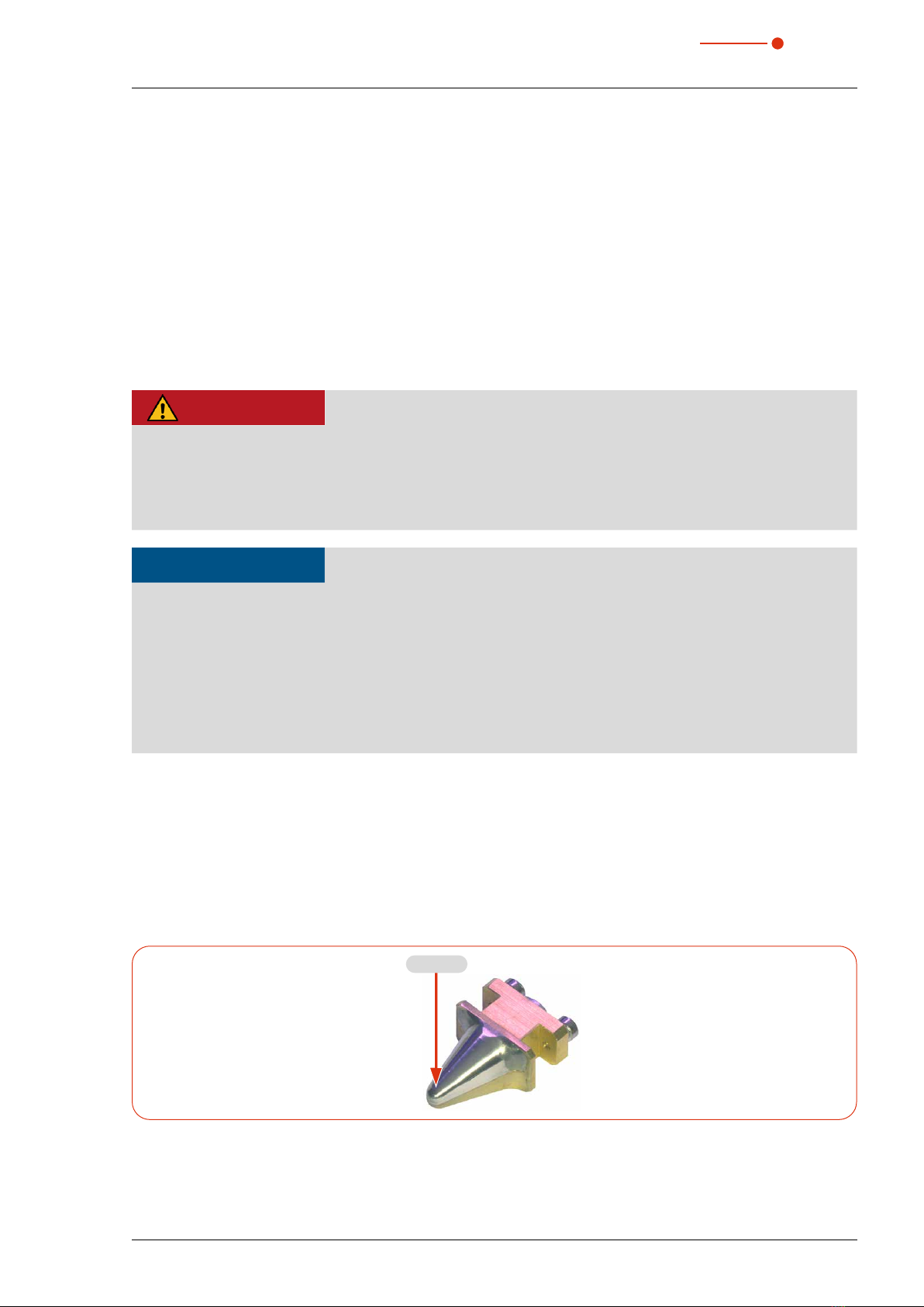
7.2.1 Prepare mounting
Mounting preparation
To prevent damage during transportation, the measuring tip is removed when delivered. It is installed with the
curved side facing the laser beam.
XMount the measuring tip according to chapter 11.3 on page68.
Fig. 7.1:
Pinhole
Measuring tip
FocusMonitor FM+
35,0(
6
18 Revision 08 EN - 08/2023
1. Switch off the laser beam.
2. Ensure that moving parts, e.g. robot arms, etc. are at a standstill and that they cannot be set in motion
unintentionally.
3. Check the space available before installing the device, especially the required space for the connection
cables and hoses.
Fig. 7.2:
z=120mm
y= max. 22mm
Range of motion of the horizontal and vertical carrier
The range of motion of the horizontal and vertical carrier can be restricted in the LDS (locked area).
A locked area can be set according to chapter chapter9.5.1 „Define locked area“ on page37.
7.2.2 Possible mounting positions
The device can be installed in any mounting position. The position and diameter of the mounting holes on the
top and bottom of the device are identical.
Standard installation
The standard position of the device is intended for a beam incidence from above.
Upside down installation with rotated measuring tip
In case of limited accessibility in the laser system, the device can be mounted in an upside down installation
with rotated measuring tip. Due to the symmetrically designed housing, upside down mounting is possible
without additional components, see chapter11.3 „Check/replace the measuring tip“ on page68.
Installation with horizontal beam incidence
For operation with horizontal beam incidence, the device can also be installed on a vertical mounting surface.
The device can be mounted with the carriers pointing up or down. Pay particular attention to secure fastening
in this mounting position.
Standard installation
Mounting surface
Mounting surface
Beam incidence
Installation with
horizontal beam incidence
Mounting surface
Mounting surface
Beam incidence
Upside down installation
with rotated measuring tip
Beam incidence
Mounting surface
Mounting surface
Fig. 7.3: Possible mounting positions of the device

FocusMonitor FM+ 35,0(6
19
Revision 08 EN - 08/2023
7.2.3 Align the device
Only use a pilot laser for alignment.
DANGER
Serious eye or skin injury due to laser radiation
If the laser beam hits the stationary measuring tip located in the measurement aperture, scattered or
directed reflection
of the laser beam occurs (laser class 4).
X
Wear suitable gloves and move the measuring tip out of the measurement aperture.
CAUTION
Risk of injury caused by rotating or moving parts
The hand or fingers can be crushed in the travel range of the horizontal and vertical carrier.
There is a risk of injury due to the rotating measuring tip.
X
Do not reach into the range of motion of the horizontal and vertical carrier.
X
Only align the device while the measuring tip is stationary.
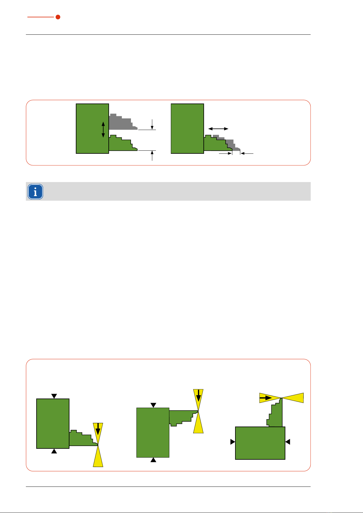
Position of the device to the laser beam
For the FM+, a perpendicular beam incidence with respect to the x-y plane must be ensured.
The vertical alignment in the z-axis depends mainly on the expected focusing plane position.
The maximum vertical stroke of the device is 120 mm.
The focusing plane should be in the middle of the measuring range of the z-axis. Depending on the mounting
position, this is approx. 60 mm above or below the park position of the device.
Fig. 7.4:
Focusing
plane
60mm
60mm
Focus lenght f z
y
Standard installation
Park position
Upside down installation
with rotated measuring tip
Park position
Measuring
range
120mm
Position of the device relative to the laser beam
FocusMonitor FM+
35,0(
6
20 Revision 08 EN - 08/2023
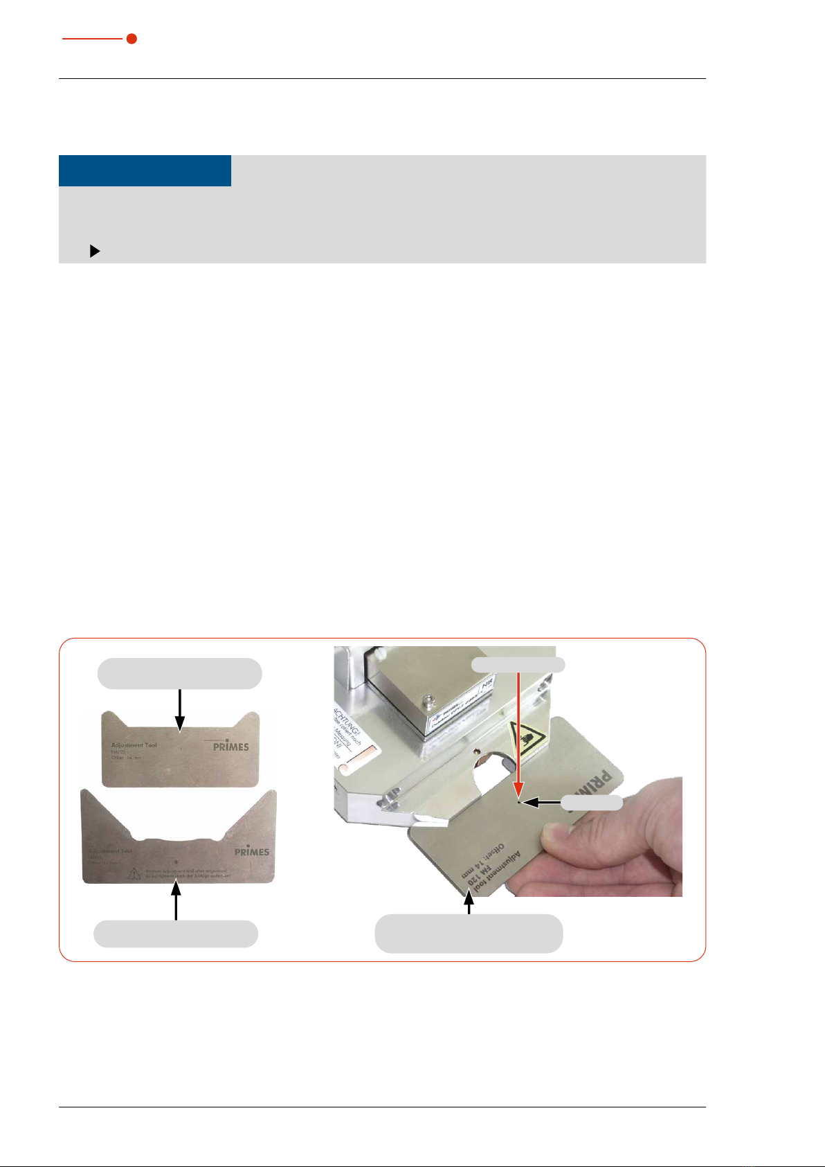
Align the device with the alignment tool
NOTICE
Damage/destruction of the alignment tool
The alignment tool can be destroyed by laser radiation.
Remove the alignment tool before turning on the laser.
For alignment of the device in the x-y plane, 2 alignment tools are included with the device.
The smaller alignment tool is held against the device, the larger one can be inserted into the slot on the device
.
The alignment tools are designed for the size of the measuring window (8x 8mm, optionally 12x 12mm or
24x 12mm) and the resulting offset. The measuring window size of the device was specified upon ordering
and cannot be changed in the LDS.
The offset is the distance from the front edge of the horizontal carrier in park position to the center of the
measuring window in y-direction (see chapter „Offset of the measurement windows“ on page21).
1. Connect the device with the LDS as described in chapter9.3 „Connect/disconnect the device to the
LDS“ on page29.
2. Open the Device control menu according to chapter9.4.2 „Open „Device control“ menu“ on page32.
3. Move the vertical carrier to the desired z-position according to chapter9.4.3 „Move vertical carrier for
setup“ on page33.
4. Hold/insert the alignment tool onto the device.
The insertable alignment tool is inserted into the central slot on the horizontal carrier.
5. Turn on the pilot laser and align the device. If the pilot laser beam hits the small hole in the alignment tool,
the unit is aligned in the x-y plane.
Fig. 7.5:
Pilot beam
Hole
Alignment tool for holding onto
the device with offset indication
Alignment tool
for plugging into the device
Alignment tool
for holding onto the device
Alignment tool of the FM+
Other manuals for FocusMonitor FM+
1
Table of contents
Other Primes Diagnostic Equipment manuals


