Primes HP-MSM-HB User manual

Revision 00 EN - 01/2021
HighPower-MSM-HighBrilliance
HP-MSM-HB, HP-MSM-HB 20 kW
LaserDiagnosticsSoftware LDS 2.98
35,0(6
Original Instructions


3
Revision 00 EN - 01/2021
HP-MSM-HB
35,0(6
IMPORTANT!
READ CAREFULLY BEFORE USE.
KEEP FOR FUTURE USE.

4Revision 00 EN - 01/2021
HP-MSM-HB
35,0(6
Table of Contents
1 Basic safety instructions 9
2 Symbol explanations 11
3 About this operating manual 12
4 Device description 13
4.1 Device models and options .....................................................................................................13
4.2 Area of Application..................................................................................................................13
4.3 Device Assembly.....................................................................................................................13
4.4 Lever to adjust the magnification.............................................................................................14
4.5 Measuring principle .................................................................................................................15
4.6 Measurement Range of the HP-MSM-HB ...............................................................................16
4.6.1 Measurement Range of the HP-MSM-HB 10 kW ......................................................16
4.6.2 Measurement Range of the HP-MSM-HB 20 kW ......................................................17
4.7 Magnetic spring ......................................................................................................................17
5 Short overview installation 18
6 Transport 19
7 Installation 20
7.1 Conditions at the installation site .............................................................................................20
7.2 Preparation and mounting position..........................................................................................20
7.3 Manually aligning the HP-MSM-HB .........................................................................................21
7.3.1 Important conditions for the position of the focused laser beam................................21
7.3.2 Mounting the cyclone................................................................................................22
7.3.3 Positioning the pilot laser beam above the cyclone ...................................................23
7.4 Mounting the Fibre Bridge (option)...........................................................................................25
8 Cooling water and compressed air connections 27
8.1 Cooling Circuit System............................................................................................................27
8.1.1 Water quality.............................................................................................................28
8.1.2 Water pressure .........................................................................................................29
8.1.3 Humidity ...................................................................................................................29
8.1.4 Water connections and water flow rate .....................................................................30
8.2 Compressed Air .....................................................................................................................30
9 Electrical connection 31
9.1 Connections............................................................................................................................31
9.2 Pin assignment .......................................................................................................................32
9.2.1 Power supply............................................................................................................32
9.2.2 Inlet external trigger ..................................................................................................32
9.2.3 Outlet internal trigger.................................................................................................32
9.2.4 Outlet internal data-transfer signal.............................................................................32
9.2.5 External Safety Circuit (Interlock) ...............................................................................33
9.3 Connection to the PC and connect power supply ...................................................................33
10 Status LEDs 35
11 Installation and configuration of the LaserDiagnosticsSoftware LDS 36
11.1 System requirements ..............................................................................................................36
11.2 Installing the software..............................................................................................................36
11.3 Ethernet configuration .............................................................................................................37

5
Revision 00 EN - 01/2021
HP-MSM-HB
35,0(6
11.3.1 Enter IP address .......................................................................................................37
11.3.2 Establishing a connection to PC)...............................................................................38
11.3.3 Changing the standard IP address of the device .......................................................39
11.3.4 Retrieve IP address automatically with DHCP............................................................40
12 Description of the LaserDiagnosticsSoftware LDS 42
12.1 Graphical user interface...........................................................................................................42
12.1.1 The menu bar ...........................................................................................................44
12.1.2 The toolbar ...............................................................................................................45
12.1.3 Menu overview..........................................................................................................46
13 Measurement 49
13.1 Safety instructions...................................................................................................................49
13.2 HP-MSM-HB with 5-fold HP-objective and cyclone.................................................................49
13.3 HP-MSM-HB with Fiber Bridge ...............................................................................................50
13.4 Prepare measurement.............................................................................................................51
13.4.1 Check list measurement settings...............................................................................51
13.4.2 Check list measurement settings...............................................................................51
13.5 Flowchart of a measurement...................................................................................................52
13.5.1 Prepare measurement...............................................................................................52
13.5.2 Set caustic limits.......................................................................................................52
13.5.3 Perform caustic measurement ..................................................................................53
13.6 Perform measurement settings in the LaserDiagnosticsSoftware LDS .....................................54
13.6.1 Sensor parameters (menu Measurement > Sensor parameter)..............................54
13.6.2 Measuring environment (menu Measurement > Environment)................................55
13.6.3 Measurement settings (menu Measurement > Single).............................................56
13.6.4 Caustic settings (menu Measurement > Caustic) ....................................................57
13.6.5 CCD settings (menu Measurement > CCD Settings)..............................................58
13.6.6 Option (advanced user only) (menu Measurement > Option)...................................60
13.6.7 CCD info (menu Measurement > CCD Info)............................................................61
13.6.8 Single measurement (menu Measurement > Single)................................................62
13.6.9 Caustic measurement (menu Measurement > Caustic)...........................................64
14 Troubleshooting 67
14.1 Error during a measurement....................................................................................................67
14.2 No measurement signal at the HP-MSM-HB ...........................................................................67
15 Maintenance and service 67
15.1 Demounting the Measuring Objective......................................................................................68
15.2 Changing the aperture at the Beam entrance ..........................................................................69
15.3 Exchanging the Protective Window in front of the Power Output Aperture...............................70
15.4 Exchanging beam splitter ........................................................................................................71
16 Accessories 72
17 Transport or Storage 73
17.1 Installing the transportation clamp...........................................................................................73
17.2 Draining the cooling circuit of the HP-MSM-HB.......................................................................74
17.3 Sealing the cooling circuit of the HP-MSM-HB ........................................................................74
17.4 Draining the cooling circuit of the PowerLossMonitor ..............................................................75
17.5 Sealing the aperture of the HB objective..................................................................................75
17.6 Packing the device..................................................................................................................76
18 Measures for the product disposal 76
19 Declaration of conformity 77
20 Technical data 78

6Revision 00 EN - 01/2021
HP-MSM-HB
35,0(6
21 Dimensions 79
21.1 Dimensions of the HP-MSM-HB..............................................................................................79
21.2 Dimensions of the HP-MSM-HB with fibre bridge....................................................................81
21.3 Dimensions of the HP-MSM-HB 20kW...................................................................................84
21.4 Dimensions of the HP-MSM-HB 20 kW with fibre bridge ........................................................86
22 Appendix A: 88
22.1 Power measurement with the PLM on the HP-MSM-HB .........................................................88
22.2 Measuring pulsed irradiation ...................................................................................................89
22.2.1 Measuring configuration selection .............................................................................91
22.2.2 Influence of the pulse parameters on the integration time control ..............................91
22.2.3 Examples for triggered measuring mode...................................................................95
22.2.4 Summary ..................................................................................................................96
23 Appendix B: Basis of laser beam diagnosis 97
23.1 Laser beam parameter............................................................................................................97
23.1.1 Rotationally symmetric beams...................................................................................98
23.1.2 Non rotationally symmetric beams ............................................................................99
23.2 Calculation of beam data ......................................................................................................100
23.2.1 Determination of the zero level ................................................................................100
23.2.2 Determination of the beam position.........................................................................101
23.2.3 Radius determination with the 2. moment method of the power density distribution101
23.2.4 Radius determination with the method of the 86% power inclusion .......................102
23.2.5 Further radius definitions (option).............................................................................103
23.3 Measurement errors ..............................................................................................................104
23.3.1 Error in determining zero level .................................................................................104
23.3.2 Saturating the signal ...............................................................................................104
23.3.3 Errors from incorrect measurement window size .....................................................105
24 Appendix: LaserDIagnosticSoftware LDS 106
24.1 File ........................................................................................................................................107
24.1.1 New (menu File > New)..........................................................................................107
24.1.2 Open (menu File > Open).......................................................................................107
24.1.3 Close/Close all (menu File > Close/Close all).........................................................107
24.1.4 Save (menu File > Save).........................................................................................107
24.1.5 Save as (menu File > Save As)...............................................................................107
24.1.6 Export (menu File > Export)...................................................................................107
24.1.7 Load measurement preferences (menu File > Load measurement preferences)..108
24.1.8 Save measurement preferences (menu File > Save measurement preferences)...108
24.1.9 Protocol (menu File > Protocol).............................................................................108
24.1.10 Print (menu File > Print).........................................................................................108
24.1.11 Print preview (menu File > Print preview)...............................................................108
24.1.12 Recently opened files (menu File > Recently opened Files)...................................108
24.1.13 Exit (menu File > Exit).............................................................................................108
24.2 Edit .......................................................................................................................................109
24.2.1 Copy (menu Edit > Copy).......................................................................................109
24.2.2 Clear plane (menu Edit > Clear plane)...................................................................109
24.2.3 Clear all planes (menu Edit > Clear all planes).......................................................109
24.2.4 Change user level (menu Edit > Change User Level).............................................109
24.3 Measurement........................................................................................................................109
24.3.1 Measuring environment (menu Measurement > Environment)..............................109
24.3.2 Sensor parameters (menu Measurement > Sensor parameter)............................111
24.3.3 Beam find settings (menu Measurement > BeamFind Settings: Beamfind .........111
24.3.4 CCD info (menu Measurement > CCD Info)..........................................................112
24.3.5 CCD settings (menu Measurement > CCD Settings)............................................113
24.3.6 LQM adjustment (menu Measurement > LQM Adjustment)..................................115

7
Revision 00 EN - 01/2021
HP-MSM-HB
35,0(6
24.3.7 Power measurement (menu Measurement > Power Measurement).....................115
24.3.8 Single (menu Measurement > Single)....................................................................115
24.3.9 Caustic measurement (menu Measurement > Caustic).........................................119
24.3.10 Start adjust mode (menu Measurement > Start Adjust mode)..............................120
24.3.11 Option (advanced user only) (menu Measurement > Option).................................121
24.4 Presentation..........................................................................................................................123
24.4.1 False colors (menu Presentation > False colors)...................................................124
24.4.2 False colors (filtered) (menu Presentation > False colors (filtered)).......................125
24.4.3 Isometry (menu Presentation > Isometry).............................................................125
24.4.4 Isometry 3D (menu Presentation > Isometry 3D) .................................................126
24.4.5 Review 86% or 2. moment (menu Presentation > Review (86%)/(2. moment)) ..127
24.4.6 Caustic (menu Presentation > Caustic) ................................................................128
24.4.7 Raw beam (menu Presentation > Raw-beam) .....................................................132
24.4.8 Symmetry check (menu Presentation > SymmetryCheck)....................................132
24.4.9 Fixed contour lines (menu Presentation > Fixed Contour Lines)...........................134
24.4.10 Variable contour lines (menu Presentation > Variable Contour Lines)...................134
24.4.11 Graphical review (menu Presentation > Graphical Review)...................................137
24.4.12 Systemstate (menu Presentation > Systemstate).................................................137
24.4.13 Evaluation parameter view (menu Presentation > Evaluation Parameter View)....138
24.4.14 Evaluate document (menu Presentation > Evaluate doc)......................................139
24.4.15 Color tables (menu Presentation > Color Tables)..................................................141
24.4.16 Toolbar (Menu Presentation > Toolbar).................................................................141
24.4.17 Position (menu Presentation > Position)...............................................................142
24.4.18 Evaluation (option) (menu Presentation > Evaluation)............................................142
24.5 Communication.....................................................................................................................144
24.5.1 Rescan bus (menu Communication > Rescan bus)..............................................144
24.5.2 Free communication (menu Communication > Free Communication).................144
24.5.3 Scan device list (menu Communication > Scan device list) .................................145
24.6 Script (menu Script) .............................................................................................................146
24.6.1 Editor (menu Script > Editor) ................................................................................146
24.6.2 List (menu Script > List) ........................................................................................146
24.6.3 Python (menu Script > Python) .............................................................................146
25 Appendix D: File formats 147
25.1 File “laserds.ini” – an Example ...............................................................................................147
25.2 Description of the MDF file format .........................................................................................148
8Revision 00 EN - 01/2021
HP-MSM-HB
35,0(6
PRIMES - The Company
PRIMES manufactures measuring devices used to analyze laser beams. These devices are employed for
the diagnostics of high-power lasers ranging from CO2lasers and solid-state lasers to diode lasers. A wave-
length range from infrared through to near UV is covered, offering a wide variety of measuring devices to
determine the following beam parameters:
• Laser power
• Beam dimensions and position of an unfocused beam
• Beam dimensions and position of a focused beam
• Beam quality factor M²
Development, production and calibration of the measuring devices is performed at PRIMES. This guarantees
optimum quality, excellent service, and a short reaction time, providing the basis for us to meet all of our
customers’ requirements quickly and reliably.
PRIMES GmbH
Max-Planck-Str. 2
64319 Pfungstadt
Germany
Tel +49 6157 9878-0
www.primes.de

9
Revision 00 EN - 01/2021
HP-MSM-HB
35,0(6
1 Basic safety instructions
Intended Use
The HighPower-MSM-HighBrilliance has been designed exclusively for measurements in the beam of high-
power lasers.
Use for any other purpose is considered as not intended and is strictly prohibited. Furthermore, intended use
requires that you observe all information, instructions, safety notes and warning messages in this operating
manual. The specifications given in chapter x, „Technical Data“, on page y apply. Any given limit values must
be complied with.
If not used as intended, the device or the system in which the device is installed can be damaged or de-
stroyed. In addition, there is an increased risk to health and life. Only use the device in such a way that there
is no risk of injury.
If you still have questions after reading this operating manual, please contact PRIMES or your supplier for
your own safety.
Observing applicable safety regulations
Observe the safety-relevant laws, guidelines, standards and regulations in the current editions published by
the state, standardization organizations, professional associations, etc. In particular, observe the regulations
on laser safety and comply with their requirements.
Necessary safety measures
The device measures direct laser radiation, but does not emit any radiation itself. However, during the mea-
surement the laser beam is directed at the device. This produces scattered or directed reflection of the laser
beam (laser class 4). The reflected beam is usually not visible.
Protect yourself from direct and reflected laser radiation while working with the device by taking the following
measures:
• If the device is moved from its aligned position, increased scattered or directed reflection of the laser
beam occurs during measuring operation. Fix the device in such a way that it cannot be moved by unin-
tentional bumping or pulling on the cables.
• Connect the laser control’s safety interlock to the device. Check that the safety interlock will switch off
the laser properly in case of error.
• The numerical aperture of the laser beam must be smaller than 0.11. Otherwise, in the lower measur-
ing positions Laser radiation from the edge of the measuring lens can be reflected into the room in an
uncontrolled manner.
• Please wear safety goggles adapted to the power, power density, laser wave length and operating
mode of the laser beam source in use.
• Depending on the laser source, it may be necessary to wear suitable protective clothing or protective
gloves.
• Protect yourself from direct laser radiation, scattered radiation, and beams generated from laser radiation
(by using appropriate shielding walls, for example, or by weakening the radiation to a harmless level).
• Use beam guidance or beam absorber elements that do not emit any hazardous substances when they
come in to contact with laser radiation and that can withstand the beam sufficiently.
• Install safety switches and/or emergency safety mechanisms that enable immediate closure of the laser
shutter.

10 Revision 00 EN - 01/2021
HP-MSM-HB
35,0(6
Necessary safety measures due to magnetic spring with strong permanent magnet
The device contains a magnetic spring made of neodymium magnets (NdFeB magnets) with a very strong
permanent magnet.
DANGER
Danger to life for persons with pacemaker or implanted defibrillator
Magnetic spring rotors consist mainly of neodymium magnets (NdFeB magnets). These can
impair the correct functioning of pacemakers.
X
If you have a cardiac pacemaker or implanted defibrillator, keep a minimum distance of 1m
from the device.
• Do not bring magnetic parts near the measuring device. Careless handling can lead to serious injuries
(bruises, broken fingers, etc.).
• Please note that magnetic springs can act like tensioned springs. The sliders spring back to their original
position as soon as they are let loose, even if he machine is disconnected from the power supply.
• Keep a safe distance to the magnetic spring with objects that can be damaged by magnetism. These
include, for example, televisions and monitors, credit cards, computers, data carriers, video tapes, me-
chanical watches, hearing aids and loudspeakers.
Employing qualified personnel
The device may only be operated by qualified personnel. The qualified personnel must have been instructed
in the installation and operation of the device and must have a basic understanding of working with high-
power lasers, beam guiding systems and focusing units.
Conversions and modifications
The device may not be modified in terms of design or safety without the express consent of the manufactur-
er. The same applies to unauthorized opening, dismantling and repair. The removal of covers is only permit-
ted within the scope of the intended use.
Liability disclaimer
Manufacturer and distributor exclude any liability for damages and injuries which are direct or indirect con-
sequences of using the device not as intended or modifying the device or the associated software without
authorization.
11
Revision 00 EN - 01/2021
HP-MSM-HB
35,0(6
2 Symbol explanations
Warning messages
The following symbols and signal words indicate possible residual risks:
DANGER
Means that death or serious physical injuries will occur if necessary safety precautions are not
taken.
WARNING
Means that death or serious physical injuries may occur if necessary safety precautions are not
taken.
CAUTION
Means that minor physical injury may occur if necessary safety precautions are not taken.
NOTICE
Means that property damage may occur if necessary safety precautions are not taken.
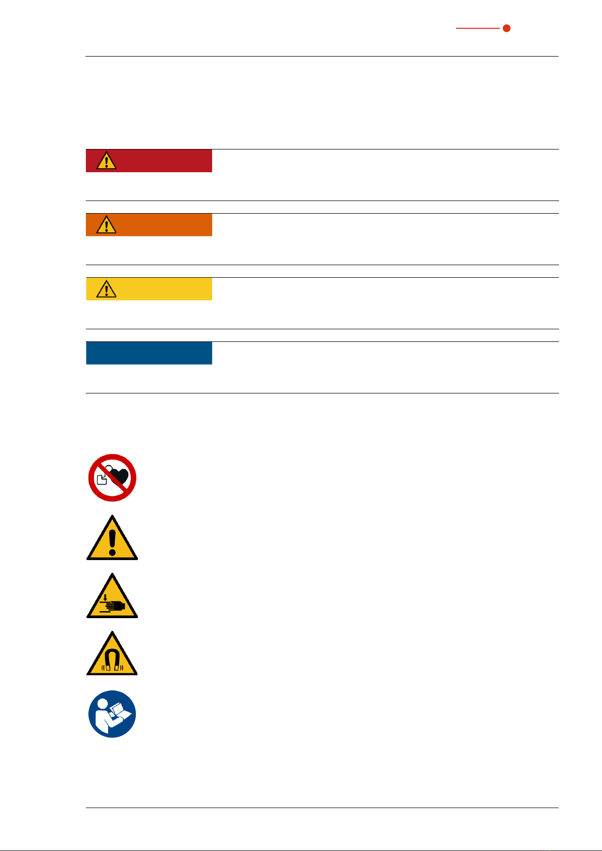
Product Safety Labels
The following symbols indicating requirements and possible dangers are used on the device:
No access for people with pacemakers or implanted defibrillators
General warning sign
Hand injuries warning
Magnetic field warning
Read and observe the operating instructions and safety guidelines before startup!
12 Revision 00 EN - 01/2021
HP-MSM-HB
35,0(6
Further symbols in this manual:
Here you can find useful information and helpful tips.
With the CE designation, the manufacturer guarantees that its product meets the requirements of
the relevant EC guidelines.
X
Call for action
3 About this operating manual
This manual describes how to work with the HP-MSM-HB and operate it with the LaserDiagnosticsSoftware
LDS 2.98 (referred to as “LDS” in the following).
The measuring device is operated via PC or via the system control.
The description of the software focuses on configuration and communication settings as well as measure-
ment operation.
This operating manual describes the software version valid at the time of printing.
Since the user software is continuously being developed further, the supplied data medium may
have a different version number. Correct functioning of the device is, however, still guaranteed with
the software.
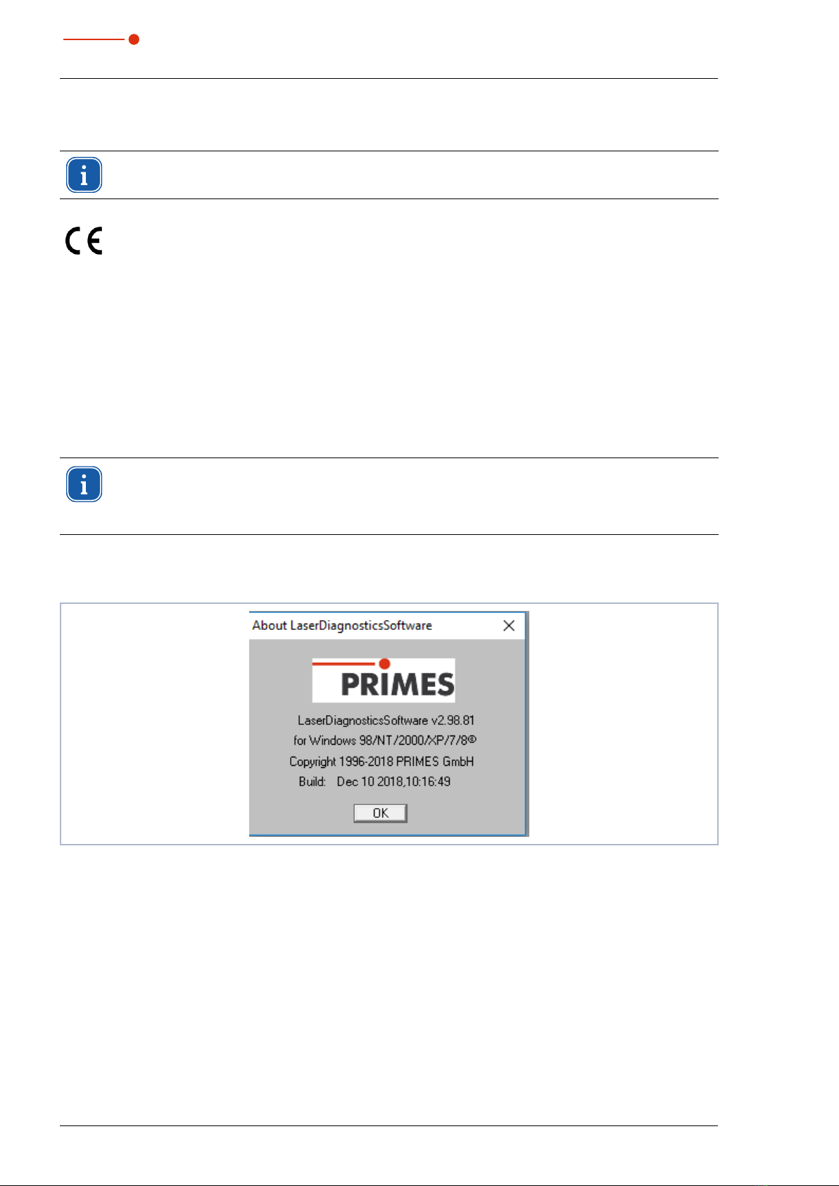
If you have any questions, please let us know the software version you are using. The software version can
be found under the following menu item: Help > About LaserDiagnosticsSoftware.
Fig. 3.1: Information regarding the current LDS software version

13
Revision 00 EN - 01/2021
HP-MSM-HB
35,0(6
4 Device description
4.1 Device models and options
There are two models of HighPower-MSM-HighBrilliance:
• HP-MSM-HB and
• HP-MSM-HB 20 kW
The HP-MSM-HB is designed for a maximum beam power of 10 kW, the HP-MSM-HB 20 kW for a maxi-
mum of 20 kW.
The maximum travel distance zmax is 120 mm for the 10 kW model and 40 mm for the 20 kW model.
For the measurement of fiber lasers, the HP-MSM-HB can optionally be equipped with a measuring bridge
with fiber adapter.
Another option is to measure the laser power with a PowerLossMonitor PLM (additional device).
4.2 Area of Application
The HP-MSM-HB is intended for the analysis of the focused beam in the diameter range between 20µm
up to 1000µm. In the measuring range the power density distribution can be measured individually in up to
50measuring planes. The beam caustic is then made up of these measuring planes.
The beam geometries (beam position, beam radius and semiaxes – lengths as well as the dumping of the
semiaxes to the device axes) are determined for each plane according to the procedures described in the
standard ISO 11146 (2. moment and 86 % power inclusion). By means of these beam geometries the beam
propagation parameters (focus position, focus radius, Rayleigh length, divergence, M², K and beam param-
eter product) are determined. By means of the measuring data for the semiaxes of the beam, the ellipticity of
the focus and the astigmatic difference are determined according to ISO 11146.
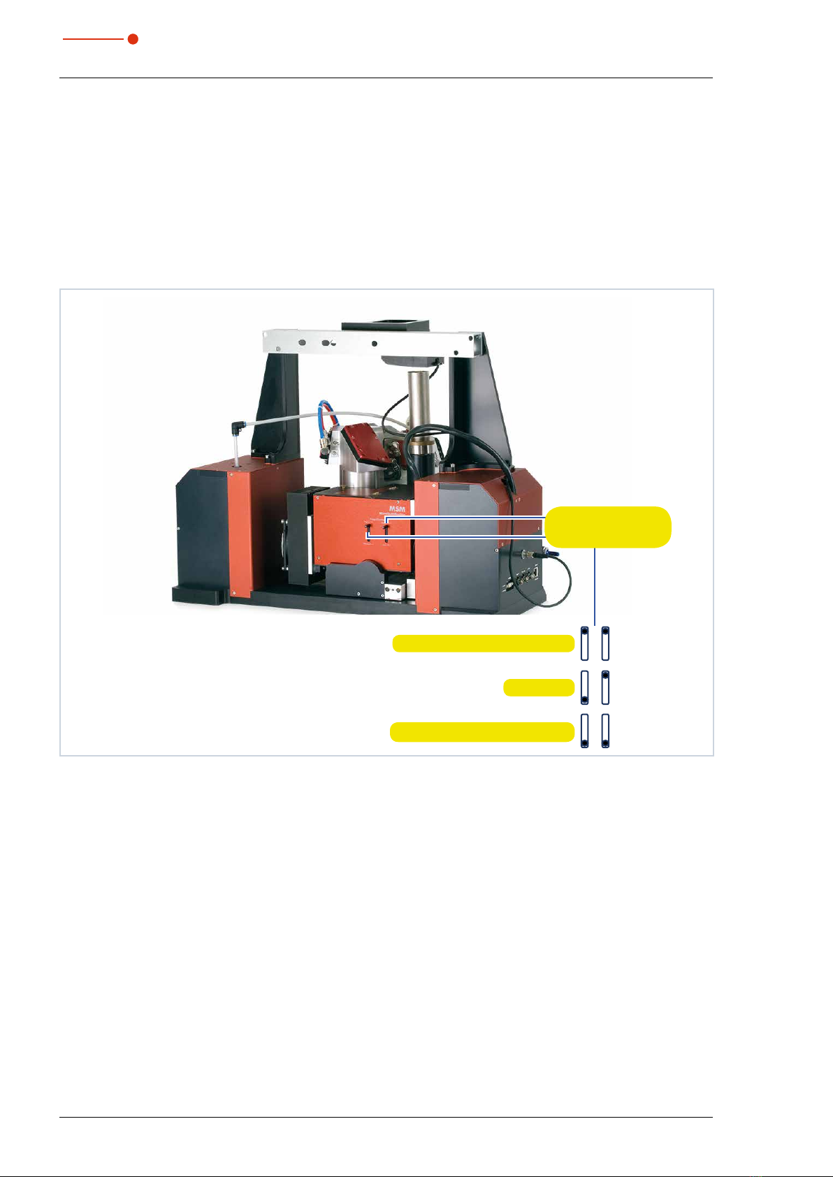
4.3 Device Assembly
Z-Axis-Drive
High Brilliance
Measuring Objektive
Beam Entrance
HighPower
Beam Absorber
Z-Axis-Drive
Fig. 4.1: Komponents of the HP-MSM-HB
14 Revision 00 EN - 01/2021
HP-MSM-HB
35,0(6
4.4 Lever to adjust the magnification
There are two levers on the side of the device for adjusting the magnification. With the help of these two
levers, either a magnification objective or an adjustment lens can be inserted into the beam path.
The magnification objective can be inserted into the beam path on the image side, directly behind a filter
wheel, by moving both levers to the upper position.
The alignment objective simplifies the beam search, since it reduces the size of the image and the required
positioning accuracy of the HP-MSM-HB is reduced by the reduction.
The alignment objective can also be inserted into the beam path on the image side by moving both levers to
the lower position.
Lever to adjust the
magnification
Magnification Objective (High)
Alignment Objective (Low)
Standard
Fig. 4.2: Levers to adjust the magnification

15
Revision 00 EN - 01/2021
HP-MSM-HB
35,0(6
4.5 Measuring principle
There are several beam splitters integrated in the measuring objective so that 99.9% of the laser power is
guided to appropriately dimensioned absorbers via the beam splitter. The laser beam is attenuated by further
optical elements in the device until it can be guided to a CCD sensor.
Measuring Plane
Upper Limit
Mirrows
Trigger diode
Filter Wheel
Lower Limit
Measuring Objective
Magnification Objective (MO)
Absorber
Laser Beam
Absorber
Alignment Objectiv (JO)
CCD-Sensor
Fixed Filter
Prisms
Fig. 4.3: Principle illustration of the optomechanical design
16 Revision 00 EN - 01/2021
HP-MSM-HB
35,0(6
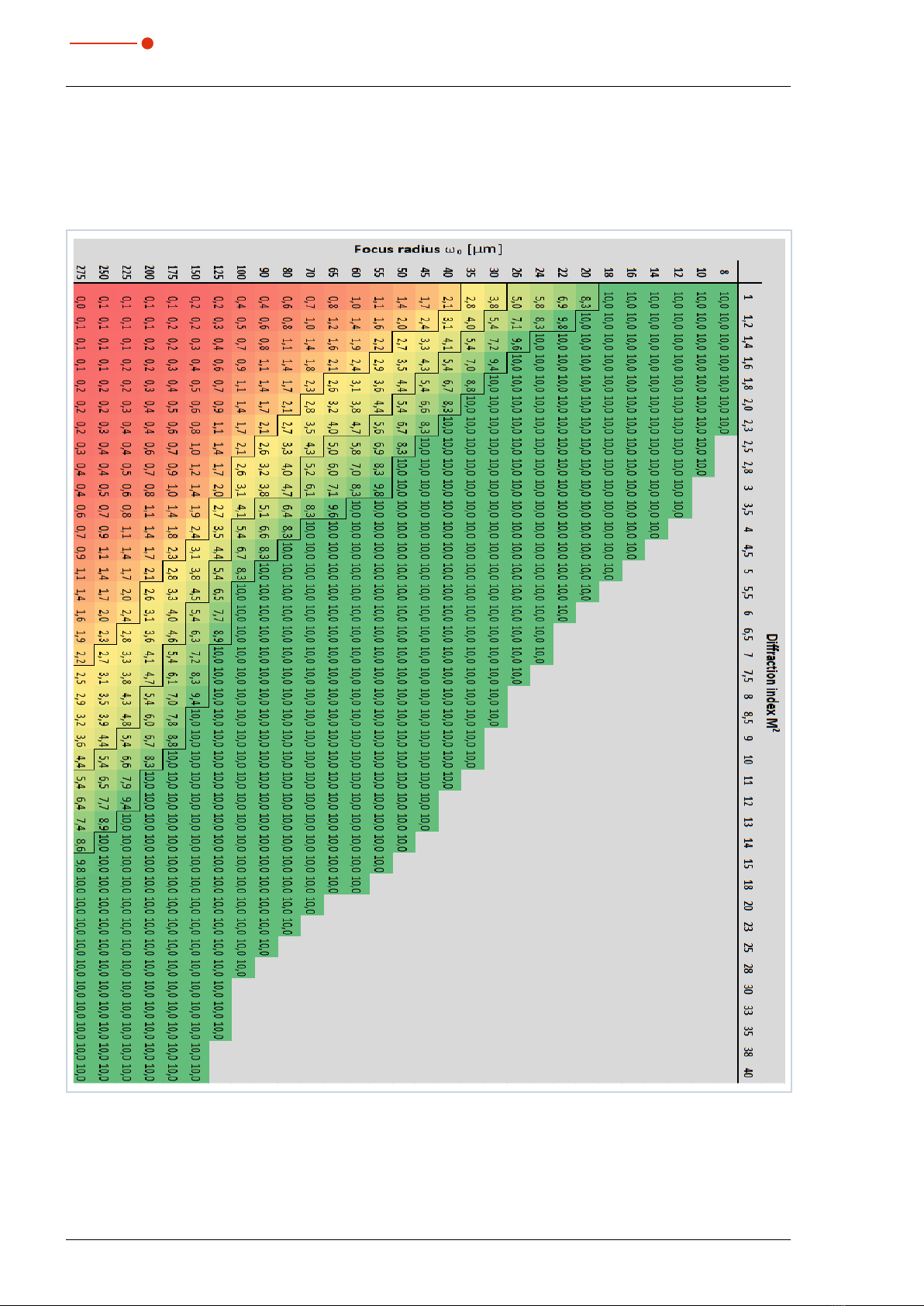
4.6 Measurement Range of the HP-MSM-HB
4.6.1 Measurement Range of the HP-MSM-HB 10 kW
Tab. 13.2 shows the correlation between power, diffraction index M² and the focus radius.
Tab. 4.1: Power in kW as a function of the diffraction index M² and the focus radius
17
Revision 00 EN - 01/2021
HP-MSM-HB
35,0(6
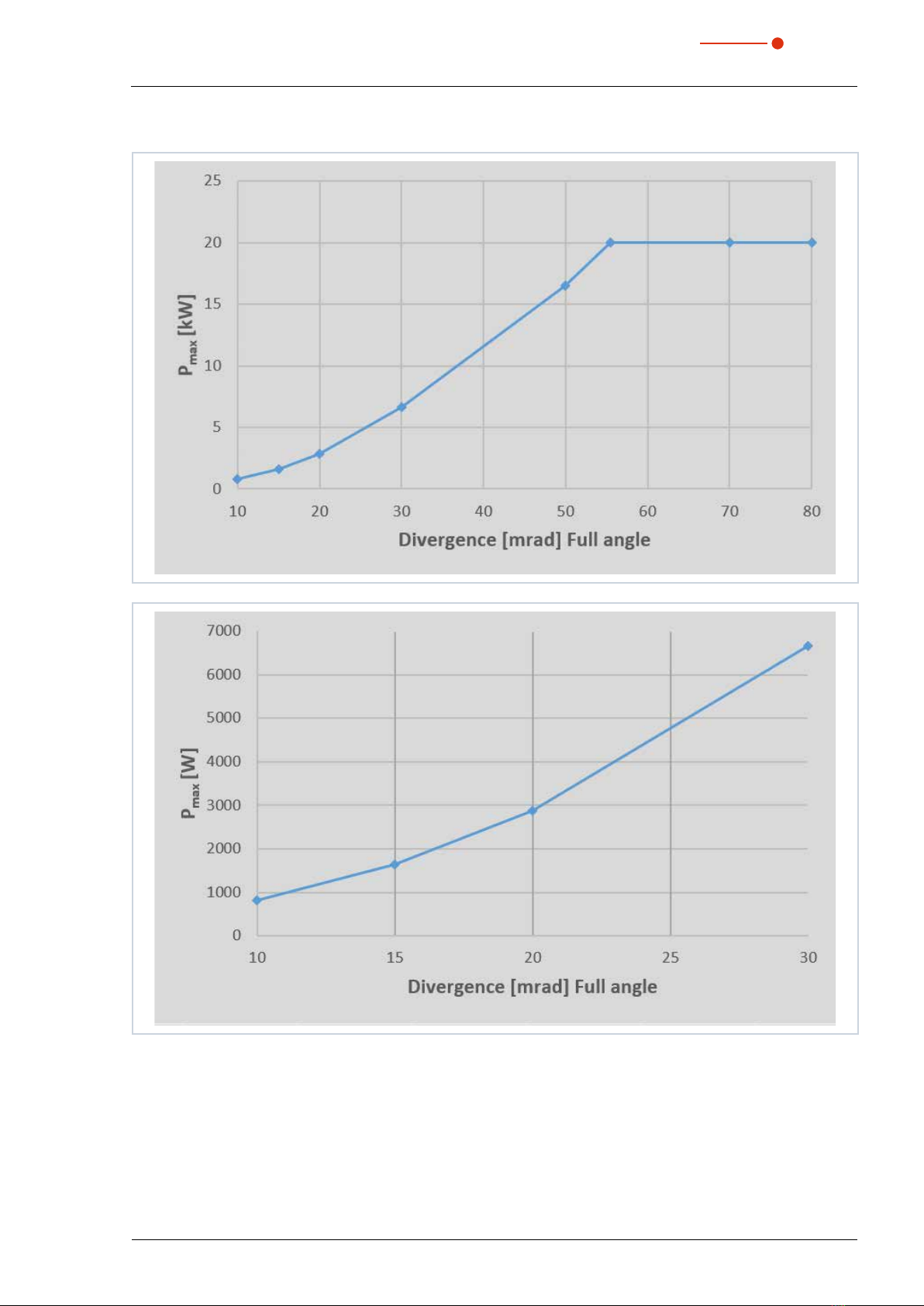
4.6.2 Measurement Range of the HP-MSM-HB 20 kW
Fig. 4.4: Maximum power as a function of the laser divergence angle
4.7 Magnetic spring
With the HighBrilliance measuring objective, a magnetic spring is mounted, which counteracts to the weight
of the measuring objective and thus relieves the traversing motors of the z-axis. Please note the warnings in
this instructions when handling the magnetic spring.

18 Revision 00 EN - 01/2021
HP-MSM-HB
35,0(6
5 Short overview installation
This short overview informs you in advance about necessary protective measures, media necessary for opera-
tion and required connecting elements.
1. Taking safety precautions Chapter 1 on page 9
DANGER
Danger to life for persons with pacemaker or implanted defibrillator
Magnetic spring rotors consist mainly of neodymium magnets (NdFeB magnets). These
can impair the correct functioning of pacemakers..
X
If you have a cardiac pacemaker or implanted defibrillator, keep a minimum distance of
1m from the device.
2. Disassemble the transport lock Chapter 6 on page 19
3. Alignment to the laser beam and stable mounting
• An alignment tool is included in the scope of delivery
• You need 6 screws M8x1 and 2 screws for the mounting holes Ø 6.6 mm
Chapter 7 on page 20
4. Installing the water-cooling
• Connection diameter 12 mm (16 mm for 20 kW-model)
• Flow rate 7l/min - 8l/min (14 l/mi - 16 l/min for 20 kW-model)
Chapter 8.1 on page 27
5. Connecting the compressed air
• Compressed air according to ISO 8573-1: 2010: 6:4:4.
• 0,5 bar - 1 bar
• Connection diameter 6 mm
Chapter 8.2 on page 30
6. Electrical connection
• Establish voltage supply
• External safety switch (interlock)
Chapter 9 on page 31
7. Connection with the PC
• Connection via Ethernet
Chapter 11.3.2 on page 38
8. Installing the LaserDiagnosticsSoftware LDS on the PC
• Software is part of the scope of delivery
Chapter 11 on page 36
19
Revision 00 EN - 01/2021
HP-MSM-HB
35,0(6
6 Transport
WARNING
Risk of injury when lifting or dropping the device
Lifting and positioning heavy devices can, for example, stress intervertebral disks and cause
chronic changes to the lumbar or cervical spine. The device may fall.
X
Use a lifting device to lift and position the device.
X
Without a lifting device, several people must lift and position the device.
NOTICE
Damaging/destroying the device
Optical components may be damaged if the device is subjected to hard shocks or is allowed
to fall.
X
Handle the measuring device carefully when transporting or installing it.
X
To avoid contamination, close the measuring objective with the cover provided.
X
Only transport the device in the original PRIMES transport box (option).
NOTICE
Damaging/destroying the device
The device must only be transported with a mounted lock..
X
Keep the transport lock in a safe place for future reuse.
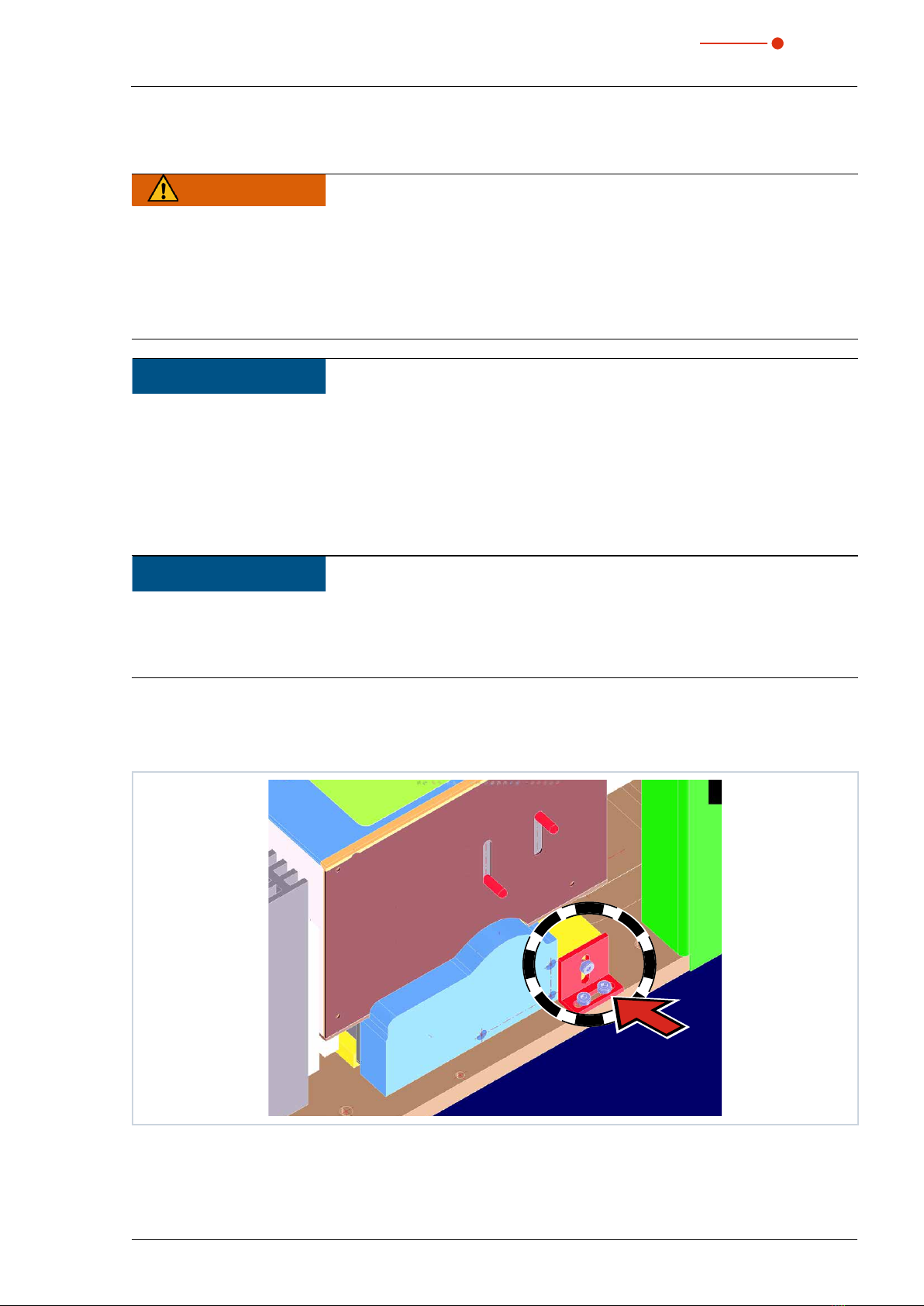
After unpacking the device, the transport lock has to be removed first. The transport lock secures the linear
actuator of the z-axis. It is located on the bottom plate and is fastened by means of 3 screws (see Fig. 6.1 on
page 19).
Fig. 6.1: Position of the transport lock
Keep this transport lock in a safe place, as it should be reassembled before each transport of the device.

20 Revision 00 EN - 01/2021
HP-MSM-HB
35,0(6
7 Installation
7.1 Conditions at the installation site
• The device must not be operated in a condensing atmosphere.
• The ambient air must be free of organic gases.
• Protect the device from splashes of water and dust.
• Operate the device in closed rooms only.
7.2 Preparation and mounting position
DANGER
Danger to life for persons with pacemaker or implanted defibrillator
Magnetic spring rotors consist mainly of neodymium magnets (NdFeB magnets). These can
impair the correct functioning of pacemakers..
X
DO NOT install the device if you have a cardiac pacemaker or implanted defibrillator. Keep a
minimum distance of 1m from the device.
DANGER
Serious eye or skin injury due to scattered radiation
The numerical aperture (NA) of the laser beam has to be smaller than 0.11 in order to ensure
that no scattered radiation occurs on the corner of the objective..
X
Wear safety goggles which are adapted to the used laser wavelength.
X
When mounting the device, please ensure that it cannot be moved by unintentional pushes
or pulling the cables or hoses..
X
Shield the device from scattered radiation.
WARNING
Danger of injuries due to a strong magnetic attraction
The magnet spring sliders can exert considerable forces as soon as they are close enough
to other sliders or iron. If they are not handled with the utmost care, this can lead to serious
injuries (contusions, broken fingers, etc.).
X
The magnet spring must only be mounted or demounted by trained personnel. Handle the
magnet spring with the utmost care when modifying the objective.
NOTICE
Danger of damage due to a strong magnetic field.
Magnet spring sliders mainly consist of very strong magnets.
X
Keep a safety distance to all devices and parts which could be damaged by magnetism, e.g.
TVs and screens, credit cards, computers, data mediums, video tapes, mechanical clocks,
hearing aids and loud speakers.
Table of contents
Other Primes Diagnostic Equipment manuals


