Primes MicroSpotMonitor Plus HighBrilliance User manual

Revision 00 EN - 02/2022
MicroSpotMonitor+ HighBrilliance
MSM+ HB10, MSM+ HB20
LaserDiagnosticsSoftware LDS
35,0(6
Original Instructions
MicroSpotMonitor MSM+ HB10


3
Revision 00 EN - 02/2022
MSM+ HB
35,0(6
IMPORTANT!
READ CAREFULLY BEFORE USE.
KEEP FOR FUTURE USE.

4Revision 00 EN - 02/2022
MSM+ HB
35,0(6
Table of Contents
1 Basic safety notes 9
2 Symbols and conventions 11
3 About this operating manual 12
4 Device description 13
4.1 Device types ...........................................................................................................................13
4.2 Functional description .............................................................................................................13
4.3 Measuring principle .................................................................................................................15
4.4 Measurement Range of the MSM+ HB....................................................................................16
4.4.1 Measurement Range of the MSM+ HB10 .................................................................16
4.4.2 Measurement Range of the MSM+ HB20 .................................................................17
4.5 Optical displays ......................................................................................................................18
4.6 Explanation of the product safety labels ..................................................................................19
4.7 Scope of delivery and accessories ..........................................................................................21
5 Quick overview installation 22
6 Transport and storage 23
6.1 Warning messages..................................................................................................................23
6.2 Removing transport lock .........................................................................................................24
6.3 Installing transport lock............................................................................................................24
6.4 Draining the cooling circuit of the MSM+ HB ...........................................................................25
6.5 Sealing the cooling circuit of the MSM+ HB.............................................................................25
6.6 Sealing the aperture of the HB objective..................................................................................26
6.7 Packing the device..................................................................................................................26
7 Mounting 27
7.1 Conditions at the installation site .............................................................................................27
7.2 Mounting position ...................................................................................................................28
7.3 Aligning the MSM+ HB ...........................................................................................................28
7.3.1 Important conditions for the position of the focused laser beam................................28
7.3.2 Mounting the cyclone................................................................................................29
7.3.3 Moving camera housing to axis center position ........................................................30
7.3.4 Positioning the pilot laser beam above the cyclone ...................................................31
7.4 Mounting the Fibre Bridge (option)...........................................................................................32
8 Connections 35
8.1 Overview of the connections ...................................................................................................35
8.2 Power supply (24V) .................................................................................................................36
8.3 Ethernet (LAN).........................................................................................................................36
8.4 Safety Circuit...........................................................................................................................37
8.5 Safety Circuit PLM In (option) ..................................................................................................38
8.6 Safety Circuit Fiber Out (option)...............................................................................................38
8.7 Inlet external trigger (In) ...........................................................................................................38
8.8 Outlet internal trigger (Out) ......................................................................................................38
8.9 Cooling water .........................................................................................................................39
8.9.1 Connecting water supply .........................................................................................39
8.9.2 Danger to the device ................................................................................................41
8.9.3 Parameters of cooling water connection ...................................................................41
8.10 Compressed Air .....................................................................................................................43

5
Revision 00 EN - 02/2022
MSM+ HB
35,0(6
9 Measurement 44
9.1 Warning messages..................................................................................................................44
9.2 Preparing measurement ..........................................................................................................45
9.2.1 Measurement process ..............................................................................................45
9.2.2 MSM+ HB with Fiber Bridge (option).........................................................................45
9.3 Connect / disconnect the device with the LaserDiagnosticsSoftware LDS...............................47
9.3.1 Switch on the device and connect it to the LDS........................................................47
9.3.2 If the device does not appear in the connections window .........................................49
9.3.3 Change the network address of a connected device.................................................49
9.3.4 Disconnect and switch off the device ........................................................................50
9.4 General procedure for measuring ............................................................................................51
9.4.1 Open the „Device control“ menu ...............................................................................51
9.4.2 Move camera housing to desired z-position ..............................................................51
9.4.3 Open a measuring mode with adapted toolbench.....................................................52
9.4.4 Configure and save measurement settings................................................................53
9.4.5 Messages in the LaserDiagnosticsSoftware LDS during measurement......................56
9.5 Single planes measurement ....................................................................................................57
9.5.1 Configure settings.....................................................................................................57
9.5.2 Configure advanced settings.....................................................................................60
9.5.3 Measure a plane .......................................................................................................63
9.5.4 Measure further planes .............................................................................................65
9.6 Continuous plane measurement (Monitor) ...............................................................................66
9.6.1 Configure settings.....................................................................................................66
9.6.2 Configure advanced settings.....................................................................................69
9.6.3 Aligne the MSM+ HB with the Monitor measuring mode ...........................................70
9.6.4 Measure a plane continuously...................................................................................71
9.7 Manual caustic measurement..................................................................................................73
9.7.1 Configure settings.....................................................................................................73
9.7.2 Configure advanced settings.....................................................................................75
9.7.3 Measure a caustic manually ......................................................................................78
9.8 Automatic caustic measurement .............................................................................................79
9.8.1 Configure settings.....................................................................................................79
9.8.2 Configure advanced settings.....................................................................................80
9.8.3 Measure a caustic automatically ...............................................................................83
9.9 Beam pointing.........................................................................................................................84
9.9.1 Configure settings.....................................................................................................85
9.9.2 Configure advanced settings.....................................................................................86
9.9.3 Measure beam pointing stability................................................................................87
9.10 Fiber mode measurement .......................................................................................................88
10 Troubleshooting 89
10.1 Error during a measurement....................................................................................................89
10.2 No measurement signal at the MSM+ HB ...............................................................................89
11 Maintenance and service 90
11.1 Maintenance intervals..............................................................................................................90
11.2 Cleaning the device surface ....................................................................................................90
11.3 Spare parts .............................................................................................................................90
11.4 Exchange wear parts ..............................................................................................................90
11.4.1 Demount the measuring objective.............................................................................90
11.4.2 Exchange protective window in front of the power output aperture ...........................92
11.4.3 Exchange beam splitter ............................................................................................93
11.4.4 Change aperture at the beam entrance.....................................................................94
12 Measures for the product disposal 94
13 Declaration of conformity 95

6Revision 00 EN - 02/2022
MSM+ HB
35,0(6
14 Technical data 97
15 Dimensions 98
15.1 Dimensions of the MSM+ HB10 ..............................................................................................98
15.2 Dimensions of the MSM+ HB10 with fibre bridge ..................................................................100
15.3 Dimensions of the MSM+ HB20 (at zmax)................................................................................103
15.4 Dimensions of the MSM+ HB20 with fibre bridge (at zmax)......................................................105
16 Appendix 107
16.1 Appendix A: GNU GPL license notice....................................................................................107
16.2 Appendix B: Using a PLM for power measurement ...............................................................107
16.2.1 Cooling water connection .......................................................................................107
16.2.2 Electrical connections .............................................................................................108
16.2.3 Transport or storage of the PowerLossMonitor PLM ...............................................108
16.2.4 Measurement with PLM ..........................................................................................109
16.3 Appendix C: Measuring pulsed irradiation ............................................................................110
16.3.1 Trigger operation.....................................................................................................110
16.3.2 Measuring configuration selection ...........................................................................111
16.3.3 Influence of the pulse parameters on the integration time control ............................111
16.3.4 Examples for trigger operation ................................................................................115
16.3.5 Summary ................................................................................................................115

7
Revision 00 EN - 02/2022
MSM+ HB
35,0(6
8Revision 00 EN - 02/2022
MSM+ HB
35,0(6
PRIMES - The Company
PRIMES manufactures measuring devices used to analyze laser beams. These devices are employed for
the diagnostics of high-power lasers ranging from CO2lasers and solid-state lasers to diode lasers. A wave-
length range from infrared through to near UV is covered, offering a wide variety of measuring devices to
determine the following beam parameters:
• Laser power
• Beam dimensions and position of an unfocused beam
• Beam dimensions and position of a focused beam
• Beam quality factor M²
Development, production and calibration of the measuring devices is performed at PRIMES. This guarantees
optimum quality, excellent service, and a short reaction time, providing the basis for us to meet all of our
customers’ requirements quickly and reliably.
PRIMES GmbH
Max-Planck-Str. 2
64319 Pfungstadt
Germany
Tel +49 6157 9878-0
www.primes.de

9
Revision 00 EN - 02/2022
MSM+ HB
35,0(6
1 Basic safety notes
Intended use
The device has been designed exclusively for measurements in the beam of high-power lasers.
Use for any other purpose is considered as not intended and is strictly prohibited. Furthermore, intended use
requires that you observe all information, instructions, safety notes and warning messages in this operating
manual. The specifications given in chapter “14 Technical data” on page 97 apply. Any given limit values
must be complied with.
If not used as intended, the device or the system in which the device is installed can be damaged or dest-
royed. In addition, there is an increased risk to health and life. Only use the device in such a way that there is
no risk of injury.
This operating manual is an integral part of the device and must be kept in the immediate vicinity of the place
of use, accessible to personnel at all times.
Every person who is responsible for the installation, start-up or operation of the device must have read and
understood the operating manual and, in particular, the safety instructions.
If you still have questions after reading this operating manual, please contact PRIMES or your supplier for
your own safety.
Observing applicable safety regulations
Observe the safety-relevant laws, guidelines, standards and regulations in the current editions published by
the state, standardization organizations, professional associations, etc. In particular, observe the regulations
on laser safety and comply with their requirements.
Necessary safety measures
The device measures direct laser radiation, but does not emit any radiation itself. However, during the mea-
surement the laser beam is directed at the device. This produces scattered or directed reflection of the laser
beam (laser class 4). The reflected beam is usually not visible.
Protect yourself from direct and reflected laser radiation while working with the device by taking the following
measures:
• Never leave the device unattended when taking measurements.
• If the device is moved from its aligned position, increased scattered or directed reflection of the laser
beam occurs during measuring operation. Fix the device in such a way that it cannot be moved by unin-
tentional bumping or pulling on the cables.
• Connect the laser control’s safety interlock to the device. Check that the safety interlock will switch off
the laser properly in case of error.
• Install safety switches or emergency safety mechanisms that allow the laser to be switched off immedia-
tely.
• Use suitable beam guidance and beam absorber elements which do not emit any hazardous substances
when irradiated.
• Wear safety goggles adapted to the power, power density, laser wavelength and operating mode of the
laser beam source in use.
• Wear suitable protective clothing or protective gloves if necessary.
• If possible, also protect yourself from direct laser radiation and scattered radiation by using separating
protective devices that block or attenuate the radiation.

10 Revision 00 EN - 02/2022
MSM+ HB
35,0(6
Necessary safety measures due to magnetic spring with strong permanent magnet
The device contains a magnetic spring made of neodymium magnets with a very strong magnetic field.
DANGER
Danger to life for persons with pacemaker or implanted defibrillator
Magnetic spring rotors consist mainly of neodymium magnets (NdFeB magnets). These can
impair the correct functioning of pacemakers.
X
If you have a cardiac pacemaker or implanted defibrillator, keep a minimum distance of 1m
from the device.
• Do not bring magnetic parts near the measuring device. Careless handling can lead to serious injuries
(bruises, broken fingers, etc.).
• Please note that magnetic springs can act like tensioned springs. The sliders spring back to their original
position as soon as they are let loose, even if he machine is disconnected from the power supply.
• Keep a safe distance to the magnetic spring with objects that can be damaged by magnetism. These
include, for example, televisions and monitors, credit cards, computers, data carriers, video tapes, me-
chanical watches, hearing aids and loudspeakers.
Employing qualified personnel
The device may only be operated by qualified personnel. The qualified personnel must have been instructed
in the installation and operation of the device and must have a basic understanding of working with high-
power lasers, beam guiding systems and focusing units.
Conversions and modifications
The device may not be modified in terms of design or safety without the explicit consent of the manufacturer.
The same applies to unauthorised opening, dismantling and repair. The removal of covers is only permitted
within the scope of the intended use.
Liability disclaimer
Manufacturer and distributor exclude any liability for damages and injuries which are direct or indirect con-
sequences of using the device not as intended or modifying the device or the associated software without
authorization.

11
Revision 00 EN - 02/2022
MSM+ HB
35,0(6
2 Symbols and conventions
Warning messages
The following symbols and signal words indicate possible residual risks in the form of warnings:
DANGER
Means that death or serious physical injuries will occur if necessary safety precautions are not
taken.
WARNING
Means that death or serious physical injuries may occur if necessary safety precautions are not
taken.
CAUTION
Means that minor physical injury may occur if necessary safety precautions are not taken.
NOTICE
Means that property damage may occur if necessary safety precautions are not taken.
Product safety labels
The following symbols are used on the device itself to indicate imperatives and possible dangers:
No access for people with pacemakers or implanted defibrillators
General warning sign
Hand injuries warning
Magnetic field warning
Read and observe the operating instructions and safety guidelines before startup!

12 Revision 00 EN - 02/2022
MSM+ HB
35,0(6
Do not lift the device by the objective
Labeling according to WEEE directive:
The device must not be disposed of with household waste, but in a separate WEEE collection
in an environmentally friendly way.
Further symbols and conventions in this operating manual
Here you can find useful information and helpful tips.
XIndicates a simple instruction.
If several such instructions appear one below the other, then the order of their execution is irrele-
vant or they are alternative procedures.
1.
2.
...
A numbered list identifies a sequence of instructions that must be executed in the specified order.
Indicates the result of an action to explain processes that take place in the background.
Indicates an observation prompt to draw attention to visible feedback from the device or the soft-
ware.
Observation prompts make it easier to check whether an instruction was executed successfully.
Often they also guide to the next instruction.
Points to a control element that is to be pressed/ clicked.
Points to an element described in the text (for example an input field).
3 About this operating manual
This manual describes the installation and operation of the MSM+ HB and how to perform measurements
with the LaserDiagnosticsSoftware LDS 1.1.2.
For measurement operation with a PC, the LaserDiagnosticsSoftware LDS must be installed on the PC. The
LDS is included in the scope of delivery.
The software description includes a brief introduction on using the device for measurements.
For a detailed description of the software installation, file management and evaluation of the measurement
data, please refer to the separate instructions for the LaserDiagnosticsSoftware LDS.
This operating manual describes the software version valid at the time of printing. Since the operat-
ing software is subject to continuous further development, it is possible that the the supplied data
carrier may contain a higher version.
If you have any questions, please let us know the software version you are using. The software version can
be found under the following menu item: Help > About LaserDiagnosticsSoftware.
13
Revision 00 EN - 02/2022
MSM+ HB
35,0(6
4 Device description
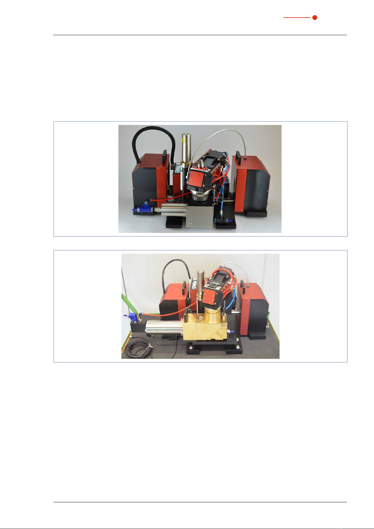
4.1 Device types
There are two types of MSM+ HighBrilliance:
• MSM+ HB10
• MSM+ HB20
Fig. 4.1: MSM+ HB10
Fig. 4.2: MSM+ HB20
The main distinguishing feature between the two devices is the absorber, which is dimensioned for different
beam powers. The MSM+ HB10 is designed for a maximum beam power of 10 kW. The MSM+ HB20 is
designed for a maximum power of 20 kW and is therefore equipped with a larger absorber.
Due to the special absorber design of the MSM + HB20, the possible maximum travel in z-direction is limi-
ted: it is 120mm for the 10kW type and 40mm for the 20kW type (not with the fiber bridge installed!).
The x- and y-axes of the 20kW type are fixed. The device cannot be moved in x- or y-direction.
4.2 Functional description
The MSM+ HB is used to analyze the focused laser beam in the range from 20 μm to 1000 μm. For this
purpose, the device records the power density distribution in the area around the focus in form of a caustic.
A caustic comprises several measurement planes (according to ISO 11146-1 at least 10). A measurement
plane maps the true power density distribution at an associated z coordinate along the optical axis of the
laser beam.
14 Revision 00 EN - 02/2022
MSM+ HB
35,0(6
The beam geometries (beam position, beam radius and azimuth angle) are determined for each plane ac-
cording to the procedures described in the standard ISO 11146 (2. moment and 86 % power inclusion).
The beam propagation parameters (focus position, focus radius, Rayleigh length, divergence, M2, K and
beam parameter product) are determined with the beam geometry data. From the measurement data for the
semi-axes of the beam, the ellipticity of the focus and the astigmatic difference are determined according to
ISO11146.
An automatic function supports the user when measuring a caustic.
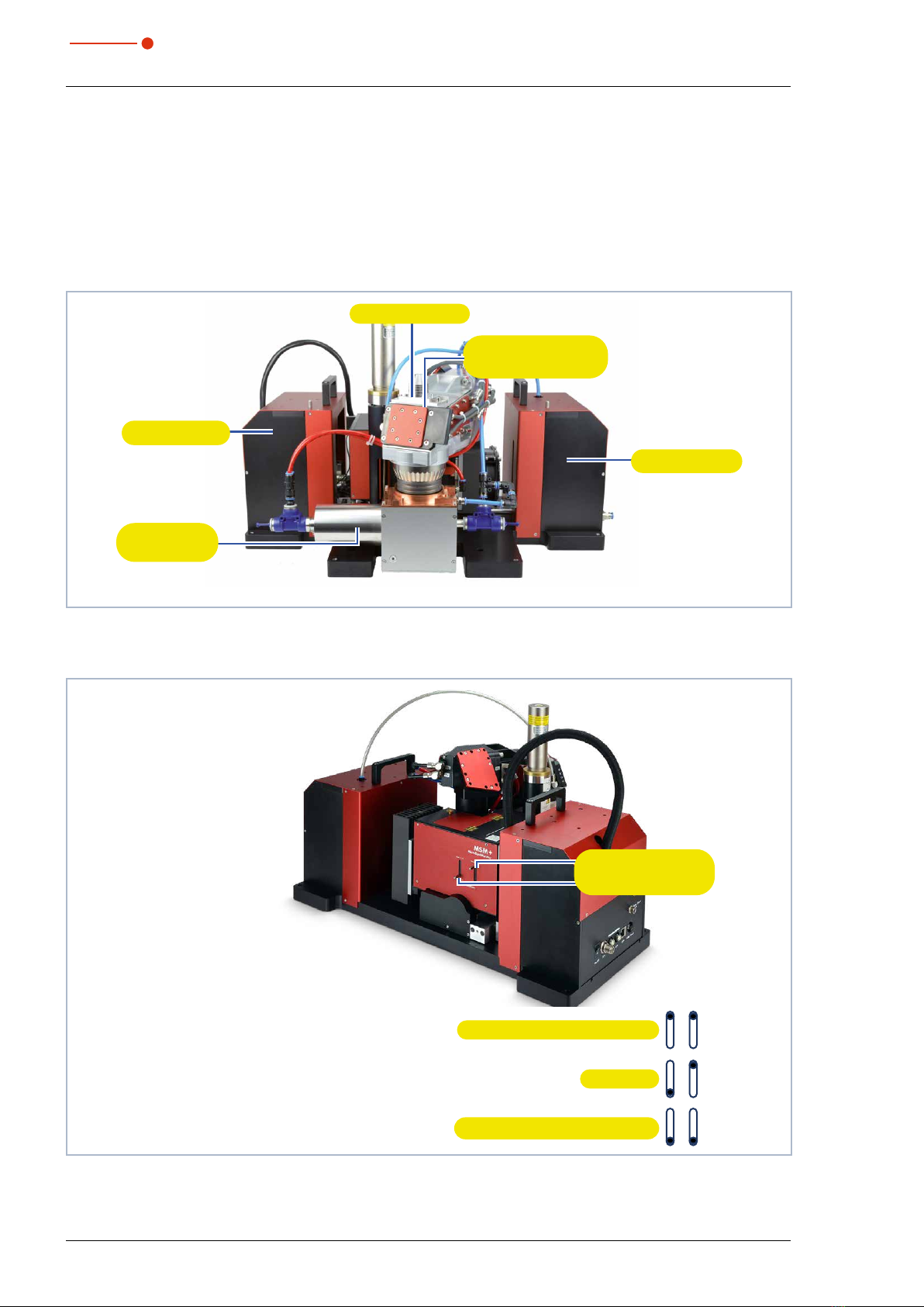
Device Assembly
Z-axis-drive
High Brilliance
measuring objective
Beam entrance
HighPower
beam absorber
Z-axis-drive
Fig. 4.3: Components of the MSM+ HB
Lever to adjust the magnification
Lever to adjust the
magnification
Magnification objective (high)
Alignment objective (low)
Standard
Fig. 4.4: Levers to adjust the magnification

15
Revision 00 EN - 02/2022
MSM+ HB
35,0(6
There are two levers on the side of the device for adjusting the magnification. With these two levers, either a
magnification objective or an adjustment lens can be inserted into the beam path.
The magnification objective can be inserted on the image side by moving both levers to the upper position.
The alignment objective can be inserted into the beam path by moving both levers to the lower position.
The alignment objective simplifys the beam search, since the measuring range (in x, y) is increased. For the
measurement, the best suited objective should be chosen.
4.3 Measuring principle
There are several beam splitters integrated in the measuring objective so that 99.9% of the laser power is
guided to appropriately dimensioned absorbers. The laser beam is attenuated by further optical elements in
the device until it can be guided to a CCD sensor.
Measuring plane
Upper limit
Mirrors
Trigger diode
Filter wheel
Lower limit
Measuring objective
Magnification objective (MO)
Absorber
Laser beam
Absorber
Alignment objectiv (AO)
CCD-sensor
Fixed filter
Prisms
Fig. 4.5: Schematic illustration of the optomechanical design

16 Revision 00 EN - 02/2022
MSM+ HB
35,0(6
4.4 Measurement Range of the MSM+ HB
4.4.1 Measurement Range of the MSM+ HB10
For a measurement, the divergence should be at least 20 mrad (full angle).
Tab. 4.1 shows the correlation between power, diffraction index M² and the focus radius.
Tab. 4.1: Maximum power in kW as a function of the diffraction index M² and the focus radius

17
Revision 00 EN - 02/2022
MSM+ HB
35,0(6
4.4.2 Measurement Range of the MSM+ HB20
valid measurement range
outside specification
Fig. 4.6: Maximum power as a function of the laser divergence angle
valid measurement range
outside specification
Fig. 4.7: Maximum power as a function of the laser divergence angle (excerpt)

18 Revision 00 EN - 02/2022
MSM+ HB
35,0(6
4.5 Optical displays
The various measuring states are indicated by different colors and light signals within the status display.
Status display
Tab. 4.2: Status display
Color Meaning
White The device is switched on and is operational.
Yellow A measurement is running.
Red Lights up briefly: a measuring plane is being recorded.
Staying lit: a device error has occurred. The device error is shown in the LaserDiagnosticsSoftware
LDS.
Tab. 4.3: Description of the colors and light states of the status display

19
Revision 00 EN - 02/2022
MSM+ HB
35,0(6
4.6 Explanation of the product safety labels
Fig. 4.8: Position of the product safety label I
There is a magnetic spring in the MSM+ HB which counteracts the weight of the measuring objective and
thus relieves the traverse motors of the z-axis.
The device contains a magnetic spring made of neodymium magnets (NdFeB magnets) with a very strong
magnetic field
No access for people with pacemakers or implanted defibrillators
A possible hazard area for persons with pacemakers or implanted defibrillators is marked with a
symbol on the device.
The magnetic spring may affect the correct functioning of pacemakers or implanted defibrilla-
tors. If you have a pacemaker or implanted defibrillator, keep a minimum distance of 1m from
the device.
Hand injuries warning due to magnetic spring
A possible hazard area for hand injuries is marked with a symbol on the device.
Note that magnetic springs can behave like tensioned springs. The sliders snap into their rest
position as soon as they are released, even if, for example, the machine is disconnected from
the power supply. Do not bring any magnetic parts near the measuring device. Careless hand-
ling can result in serious injuries (crushing, broken fingers, etc. ).
Magnetic field warning
A possible hazard area, originating from a magnetic field, is marked with a symbol on the de-
vice.
Keep a safe distance from the magnetic spring with objects that can be damaged by mag-
netism. These include, for example, televisions and monitors, credit cards, computers, data
carriers, video tapes, mechanical watches, hearing aids and loudspeakers.

20 Revision 00 EN - 02/2022
MSM+ HB
35,0(6
Hand injuries warning due to movement of camera housing
Another possible hazard area for hand injuries is marked with a symbol on the device.
The camera housing of the device can be moved along the z axis. Do not reach into the opera-
ting range of the camera housing. Careless handling may result in crushing.
Fig. 4.9: Position of the product safety label II
Do not lift the device by the objective
A possible hazard area for damage to the device due to incorrect lifting is marked with a symbol
on the device.
Do not lift or transport the device by the objective.
Fig. 4.10: Position of the product safety label III
General warning sign (Option, devices with fiber bridge only)
A possible hazard area for device damage is marked with a symbol on the fiber adapter.
Depending on the type of fiber adapter, a collision may occur at this point when moving the
device along the z axis.
This manual suits for next models
2
Table of contents
Other Primes Diagnostic Equipment manuals


