Primes FocusMonitor FM+ User manual
Revision 03/2019 EN
Translation of the original instructions
FocusMonitor FM+
LaserDiagnosticsSoftware LDS
Operating Manual
35,0(6


FocusMonitor FM+ 35,0(6
3
Revision 03/2019 EN
IMPORTANT!
READ CAREFULLY BEFORE USE.
KEEP FOR FUTURE USE.

FocusMonitor FM+
35,0(
6
4Revision 03/2019 EN
Table of contents
1 Basic safety instructions 7
2 Symbol explanations 9
3 About this operating manual 10
4 Conditions at the installation site 10
5 Introduction 11
5.1 System description .................................................................................................................11
5.2 Measuring principle .................................................................................................................12
5.3 Short overview installation .......................................................................................................13
6 Transport 14
7 Installation 14
7.1 Safety instructions...................................................................................................................14
7.2 Preparation .............................................................................................................................16
7.3 Installation position..................................................................................................................17
7.4 Align the FocusMonitorFM+ ...................................................................................................18
7.4.1 Device's position in relation to the laser beam.............................................................18
7.4.2 Align the FocusMonitorFM+ with the alignment tool ...................................................18
7.5 Install the FocusMonitorFM+ ..................................................................................................20
8 Electrical connections 21
8.1 Connections............................................................................................................................21
8.2 Pin assignment .......................................................................................................................22
8.2.1 Power supply..............................................................................................................22
8.2.2 PRIMES bus RS485....................................................................................................22
8.2.3 Trigger output (option) .................................................................................................22
8.3 Connection to the PC and establishing the power supply........................................................23
8.4 Connection of the FocusMonitorFM+ and PowerMonitor PM48/100 to the PC .....................24
9 Inert gas connection 25
10 Status display 25
11 Measuring 26
11.1 Safety instructions...................................................................................................................26
11.2 Configure FocusMonitorFM+..................................................................................................27
11.3 Connect the FocusMonitorFM+ with the LaserDiagnosticsSoftwareLDS................................28
11.3.1 Connect device...........................................................................................................28
11.3.2 Change the network address of a connected device...................................................28
11.4 Performing an automatic caustic measurement.......................................................................29
11.4.1 Selecting the measuring mode automatic caustic .......................................................29
11.4.2 Configuring the settings (Device control > Settings)..................................................30
11.4.3 Configuring advanced settings (Device control > Advanced)....................................31
11.4.4 Defining the locked area (Device control > Advanced > Locked area) ....................32
11.4.5 Traversing the axes (Device control > Advanced > Move axes)................................33
11.4.6 Rotated measuring tip (Device control > Advanced > Measuring tip)......................34
11.4.7 Coordinate system for measurements with rotated measuring tip................................35
11.4.8 Starting an automatic caustic measurement................................................................36
11.4.9 Measuring results display............................................................................................37
11.5 Determining the tool center point (TCP) using the FocusMonitorFM+......................................38
11.5.1
Position of the aperture in the measuring tip (pinhole) in relation to the horizontal carrier
.39

FocusMonitor FM+ 35,0(6
5
Revision 03/2019 EN
12 Troubleshooting 40
13 Maintenance and service 40
14 Product disposal measures 40
15 Declaration of conformity 41
16 Technical data 42
17 Dimensions 44
18 Appendix 46
18.1 System control (option) ...........................................................................................................46
18.2 Variety of detectors and measuring tips...................................................................................47
18.3 Limit values for measuring operation with CO2high power measuring tip ................................48
18.4 Limit values for measuring operation with YAG high div measuring tip .....................................50
18.5 Check/replace the measuring tip.............................................................................................52
18.5.1 Check the measurung tip............................................................................................52
18.5.2 Disassemble the measuring tip ...................................................................................52
18.5.3 Assemble the measuring tip........................................................................................53
18.6 Replace the detector...............................................................................................................54
18.6.1 Disassemble the detector ...........................................................................................55
18.6.2 Assemble the detector................................................................................................56

FocusMonitor FM+
35,0(
6
6Revision 03/2019 EN
PRIMES - The Company
PRIMES manufactures measuring devices used to analyze laser beams. These devices are employed for
the diagnostics of high-power lasers ranging from CO2lasers and solid-state lasers to diode lasers. A wave-
length range from infrared through to near UV is covered, offering a wide variety of measuring devices to
determine the following beam parameters:
• Laser power
• Beam dimensions and position of an unfocused beam
• Beam dimensions and position of a focused beam
• Beam quality factor M²
PRIMES is responsible for both the development, production, and calibration of the measuring devices. This
guarantees optimum quality, excellent service, and a short reaction time, providing the basis for us to meet all
of our customers' requirements quickly and reliably.
PRIMES GmbH
Max-Planck-Str. 2
64319 Pfungstadt
Germany
Tel +49 6157 9878-0
www.primes.de

FocusMonitor FM+ 35,0(6
7
Revision 03/2019 EN
1 Basic safety instructions
Intended Use
The FocusMonitorFM+ has been designed exclusively for measurements carried out in or near the optical
path of high-power lasers. Please observe and adhere to the specifications and limit values given in chap-
ter16, „Technical data“, on page42. Other uses are considered to be improper. The information contained
in this operating manual must be strictly observed to ensure proper use of the device.
Using the device for unspecified use is strictly prohibited by the manufacturer. By usage other than intended
the device can be damaged or destroyed. This poses an increased health hazard up to fatal injuries. When
operating the device, it must be ensured that there are no potential hazards to human health.
The device itself does not emit any laser radiation. During the measurement, however, the laser beam is
guided onto the device which causes reflected radiation (laser class 4). That is why the applying safety regu-
lations are to be observed and necessary protective measures need to be taken.
Observing applicable safety regulations
Please observe valid national and international safety regulations as stipulated in ISO/CEN/TR standards as
well as in the IEC-60825-1 regulation, in ANSI Z 136 “Laser Safety Standards” and ANSI Z 136.1 “Safe Use
of Lasers”, published by the American National Standards Institute, and additional publications, such as the
“Laser Safety Basics”, the “LIA Laser Safety Guide”, the “Guide for the Selection of Laser Eye Protection”
and the “Laser Safety Bulletin”, published by the Laser Institute of America, as well as the “Guide of Control
of Laser Hazards” by ACGIH.
Necessary safety measures
DANGER
Serious eye or skin injury due to laser radiation
Depending on the measuring principle used, the laser beam is reflected at the measuring tip
(laser class4). The reflected beam is usually not visible.
X
In measurement mode, a safety distance of one meter to the FocusMonitorFM+ must be
maintained even when wearing safety goggles and safety clothing.
X
Please take the following precautions.
If people are present within the danger zone of visible or invisible laser radiation, for example near laser
systems that are only partly covered, open beam guidance systems, or laser processing areas, the following
safety measures must be implemented:
• Please wear safety goggles (OD 6) adapted to the power, power density, laser wave length and operating
mode of the laser beam source in use.
• Depending on the laser source, it may be necessary to wear suitable protective clothing or protective
gloves.
• Protect yourself from direct laser radiation, scattered radiation, and beams generated from laser radiation
(by using appropriate shielding walls, for example, or by weakening the radiation to a harmless level).
• Use beam guidance or beam absorber elements that do not emit any hazardous substances when they
come in to contact with laser radiation and that can withstand the beam sufficiently.
• Install safety switches and/or emergency safety mechanisms that enable immediate closure of the laser
shutter.
• Ensure that the device is mounted securely to prevent any movement of the device relative to the beam
axis and thus reduce the risk of scattered radiation. This in the only way to ensure optimum performance
during the measurement.

FocusMonitor FM+
35,0(
6
8Revision 03/2019 EN
Employing qualified personnel
The device may only be operated by qualified personnel. The qualified personnel must have been instructed
in the installation and operation of the device and must have a basic understanding of working with high-
power lasers, beam guiding systems and focusing units.
Conversions and modifications
The device must not be modified, neither constructionally nor safety-related, without our explicit permission.
The device must not be opened e.g. to carry out unauthorized repairs. Modifications of any kind will result in
the exclusion of our liability for resulting damages.
Liability disclaimer
The manufacturer and the distributor of the measuring devices do not claim liability for damages or injuries
of any kind resulting from an improper use or handling of the devices or the associated software. Neither the
manufacturer nor the distributor can be held liable by the buyer or the user for damages to people, material
or financial losses due to a direct or indirect use of the measuring devices.
FocusMonitor FM+ 35,0(6
9
Revision 03/2019 EN
2 Symbol explanations
The following symbols and signal words indicate possible residual risks:
DANGER
Means that death or serious physical injuries will occur if necessary safety precautions are not
taken.
WARNING
Means that death or serious physical injuries may occur if necessary safety precautions are not
taken.
CAUTION
Means that minor physical injury may occur if necessary safety precautions are not taken.
NOTICE
Means that property damage may occur if necessary safety precautions are not taken.
The following symbols indicating requirements and possible dangers are used on the device:
Laser radiation warning
Hand injuries warning
Read and observe the operating instructions and safety guidelines before startup!
Further symbols that are not safety-related:
Here you can find useful information and helpful tips.
With the CE designation, the manufacturer guarantees that its product meets the requirements of
the relevant EC guidelines.
X
Call for action

FocusMonitor FM+
35,0(
6
10 Revision 03/2019 EN
3 About this operating manual
This documentation describes the installation and configuration of the FocusMonitorFM+ and the execution
of measurements with the LaserDiagnosticsSoftware LDS.
The LaserDiagnosticsSoftware LDS must be installed on the PC for measuring operation of the
FocusMonitorFM+. The basic version of the LaserDiagnosticsSoftware LDS is included in the scope of deliv-
ery for the device.
For a detailed description of the software installation, file management and evaluation of the measured data,
please refer to the separate operating manual LaserDiagnosticsSoftware LDS.
4 Conditions at the installation site
• The device must not be operated in a condensing atmosphere.
• The ambient air must be free of organic gases.
• Protect the device from splashes of water and dust.
• Operate the device in closed rooms only.
DANGER
Fire and explosion hazards due to scattered or directed laser radiation
When the FocusMonitorFM+ is being operated, the irradiation must be fully absorbed be-
hind the measurement zone. Fire bricks or other partly-absorbing surfaces are not suitable.
X
Use an adequate absorber. Dependent on the application, PRIMES offers suitable absorbers,
such as the PowerMonitor PM48/100.
X
Don’t store any flammable materials or highly flammable substances at the measuring loca-
tion.
FocusMonitor FM+ 35,0(6
11
Revision 03/2019 EN
5 Introduction
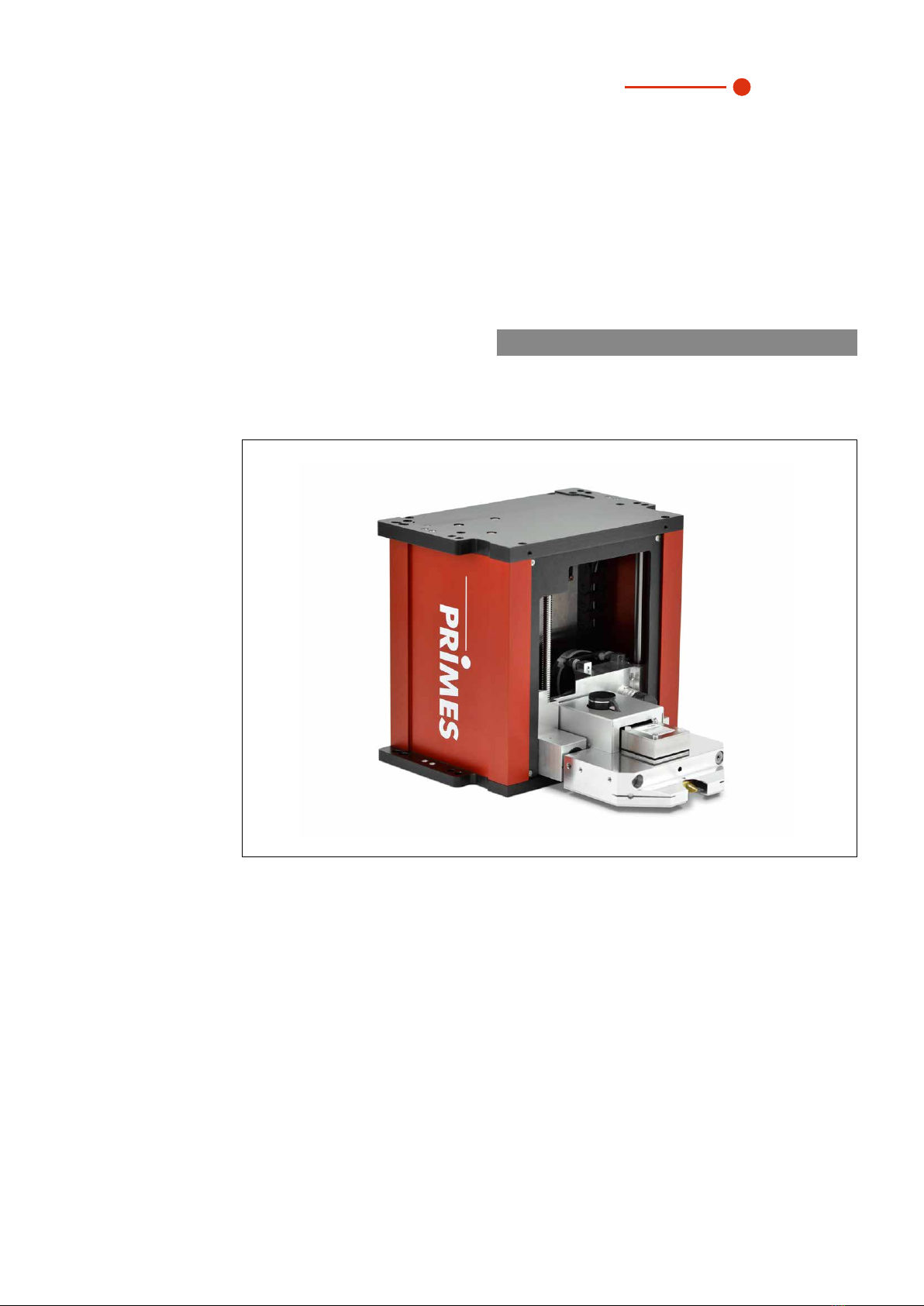
5.1 System description
The FocusMonitorFM+ is an opto-mechanical scanning measurement system for analyzing continuous
irradiation. The laser beam is scanned with a rotating measuring tip on the x-axis. Using the horizontal and
vertical carriers, the measuring tip is moved along the y- and z-axes so that the beam characteristics of the
focused laser beam can be spacially measured.
The housing of the FocusMonitorFM+ is symmetrically constructed so that it can be mounted overhead
without additional components.
The FocusMonitorFM+ has an Ethernet interface for fast and secure data exchange with computers or sys-
tem controls.
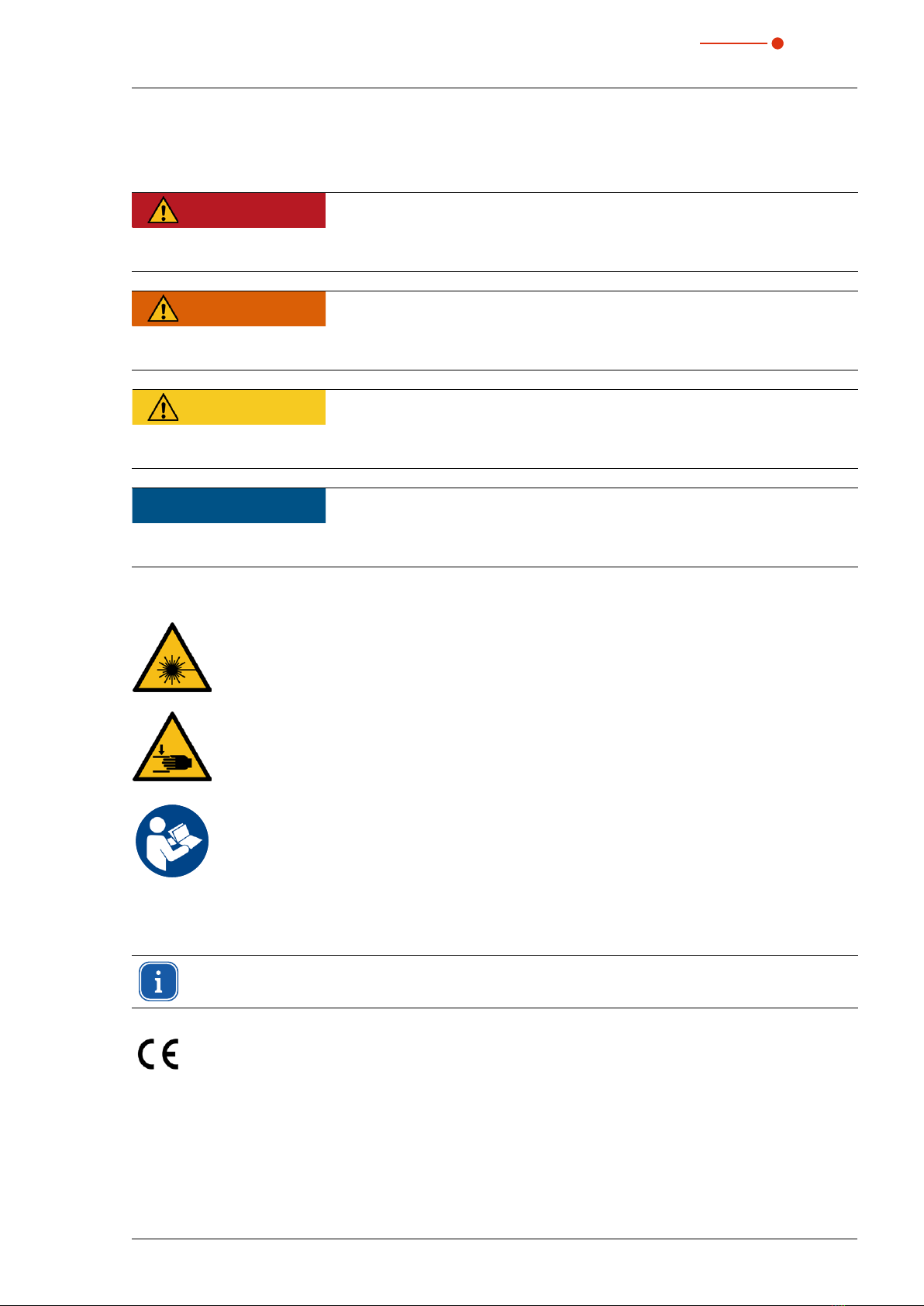
y-axis
z-axis
Horizontal carrier
Detector
Measuring tip
Vertical carrier
Fig. 5.1: Main components FocusMonitorFM+
FocusMonitor FM+
35,0(
6
12 Revision 03/2019 EN
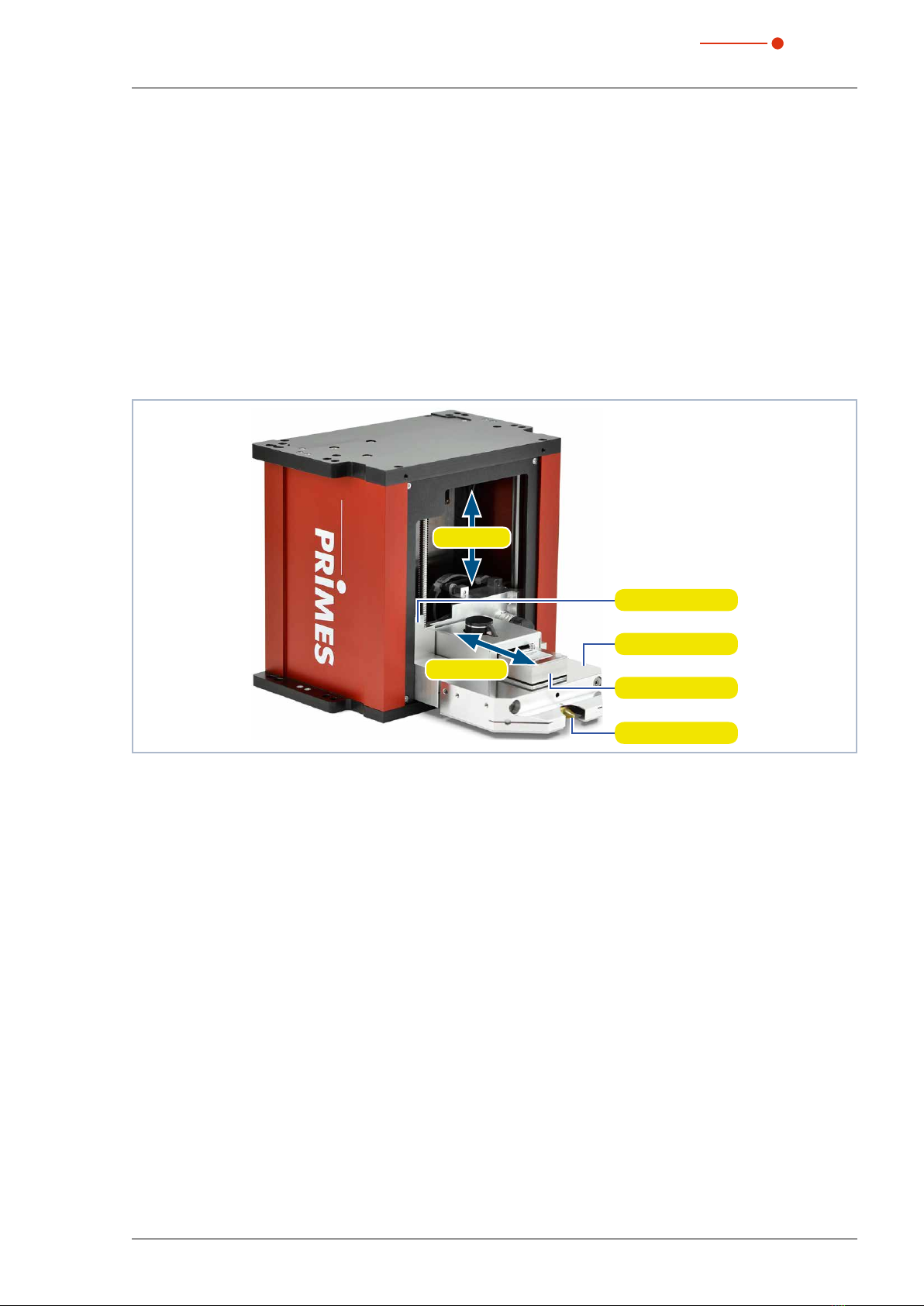
5.2 Measuring principle
The FocusMonitorFM+ is designed to analyze the focused laser beam. The device measures the spatial
power density distribution in the focus range of the processing optics. Using this information, the system
calculates the focus radius, focus position in the space, and the beam quality factor M2.
The power density distribution in the focus is measured with the FocusMonitorFM+ using a rotating measur-
ing tip that scans the beam cross section line by line in the y-direction. The tiny aperture of the measuring tip
(pinhole) separates out a small part of each beam. Mirrors then guide the measuring signal to a detector. The
measuring system can be moved automatically via an integrated z-axis. This ensures that the propagation
parameters can be determined in full by moving along the beam caustic.
Laser beam
x
z
y
Measuring tip
Detector
Fig. 5.2: Optomechanical design of the FocusMonitorFM+
The use of different detectors and measuring tips ensure that the FocusMonitorFM+ can be adjusted to spe-
cific beam diagnosis requirements within a broad wavelength and power density range. The system applica-
tions range from a few MW/cm2up to a few W/cm2. Detailed descriptions of other detectors and measuring
tips (e.g. suitable for the detection of strongly divergent beams, such as those generated by high-power
diode lasers) can be found in chapter 18.2 on page47.
FocusMonitor FM+ 35,0(6
13
Revision 03/2019 EN
5.3 Short overview installation
1. Installing the LaserDiagnosticsSoftware LDS on the computer
• Software is part of the scope of delivery
See separate Operating Manual
of the LaserDiagnosticsSoftware
LDS
2. Taking safety precautions Chapter 1 on page 7
3. Prepare Installation
• Observe safety instructions
• Make preparations
• Set installation position
Chapter 7.1 on page 14
to
chapter 7.3 on page 17
4. Electrical connection
• Establish voltage supply
Chapter 8 on page 21
5. Connect with the computer
• Via Ethernet or LAN
Chapter 8.3 on page 23
6. Connect with the PowerMonitor PM48/100
• Via RS485
Chapter 8.4 on page 24
7. Inert gas connection
• At very high power density
(CO2 > 15 – 30MW/cm²; NIR > 8 – 10MW/cm²)
Chapter 9 on page 25
8. Complete installation
• Align the device
• Mount the device firmly
Chapter 7.4 on page 18
and
chapter 7.5 on page 20
9. Perform the measurement
• Observe safety instructions
• Configure FocusMonitorFM+
• Perform a sample measurement
Chapter 11 on page 26

FocusMonitor FM+
35,0(
6
14 Revision 03/2019 EN
6 Transport
NOTICE
Damage/Destruction of the device
The device’s axes and carriers may be damaged if the device is subjected to hard shocks or
is allowed to fall.
X
Handle the device carefully when transporting or installing it.
X
Only transport the device in the original PRIMES transport box.
We recommend removing the measuring tip and placing it in the enclosed plastic case.
7 Installation
7.1 Safety instructions
Areas on the device that could be particularly hazardous for hand injuries are marked with the following pic-
togram:
Hand injuries warning
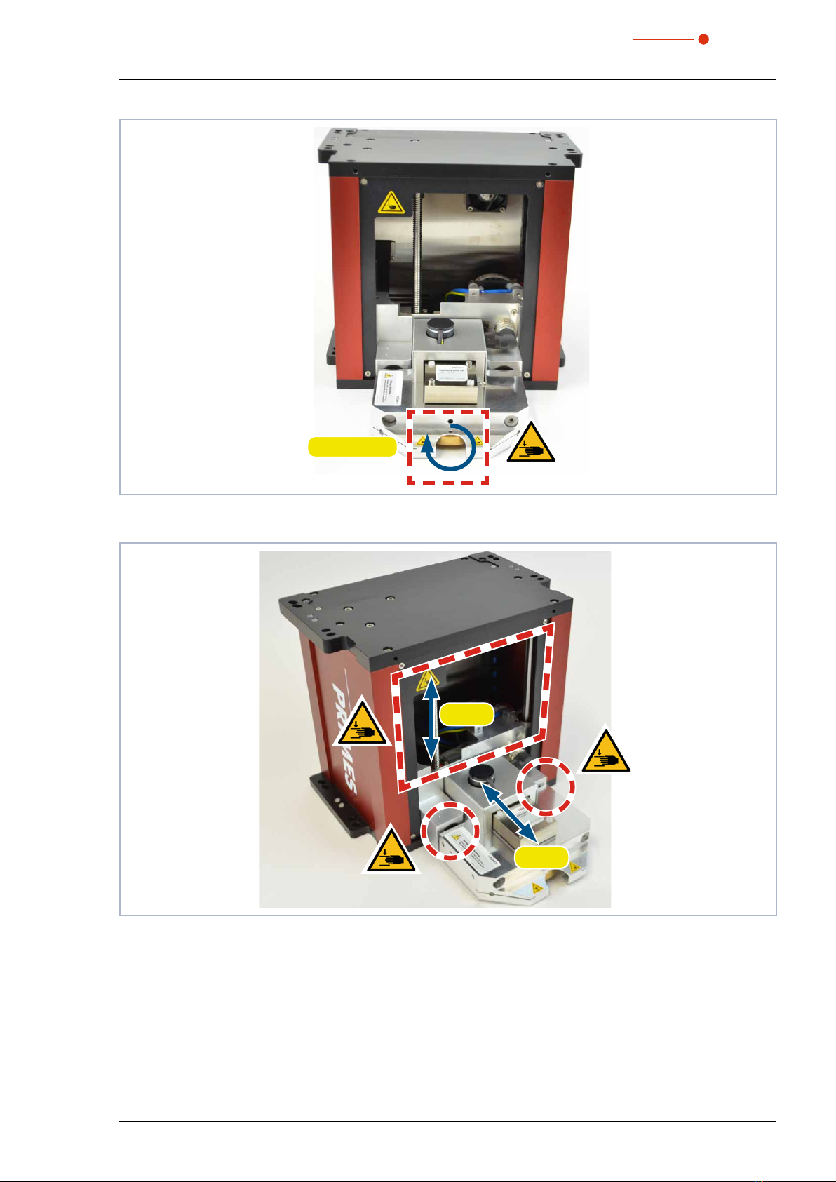
CAUTION
Risk of injury caused by rotating parts
The measuring tip of the FocusMonitorFM+ rotates at high speed during the measuring
operation. Even after the motor has been turned off, the measuring tip will continue to rotate
for a certain amount of time.
X
Do not reach into or hold any objects into the beam entrance of the measuring device (see
Fig. 7.1 on page 15).
X
After the motor has been turned off, wait until the measuring tip comes to a complete stop
(pay attention to the status display on the connection side).
CAUTION
Risk of crushing
Unlike the housing, the measuring head of the FocusMonitorFM+ can move along the z-and
y-axis.
X
Do not reach into the movement range of the measuring head (see Fig. 7.2 on page 15).
FocusMonitor FM+ 35,0(6
15
Revision 03/2019 EN
Mesuring tip
Fig. 7.1: Danger posed by rotating parts
y-axis
z-axis
Fig. 7.2: Crushing hazard at the FocusMonitorFM+
FocusMonitor FM+
35,0(
6
16 Revision 03/2019 EN
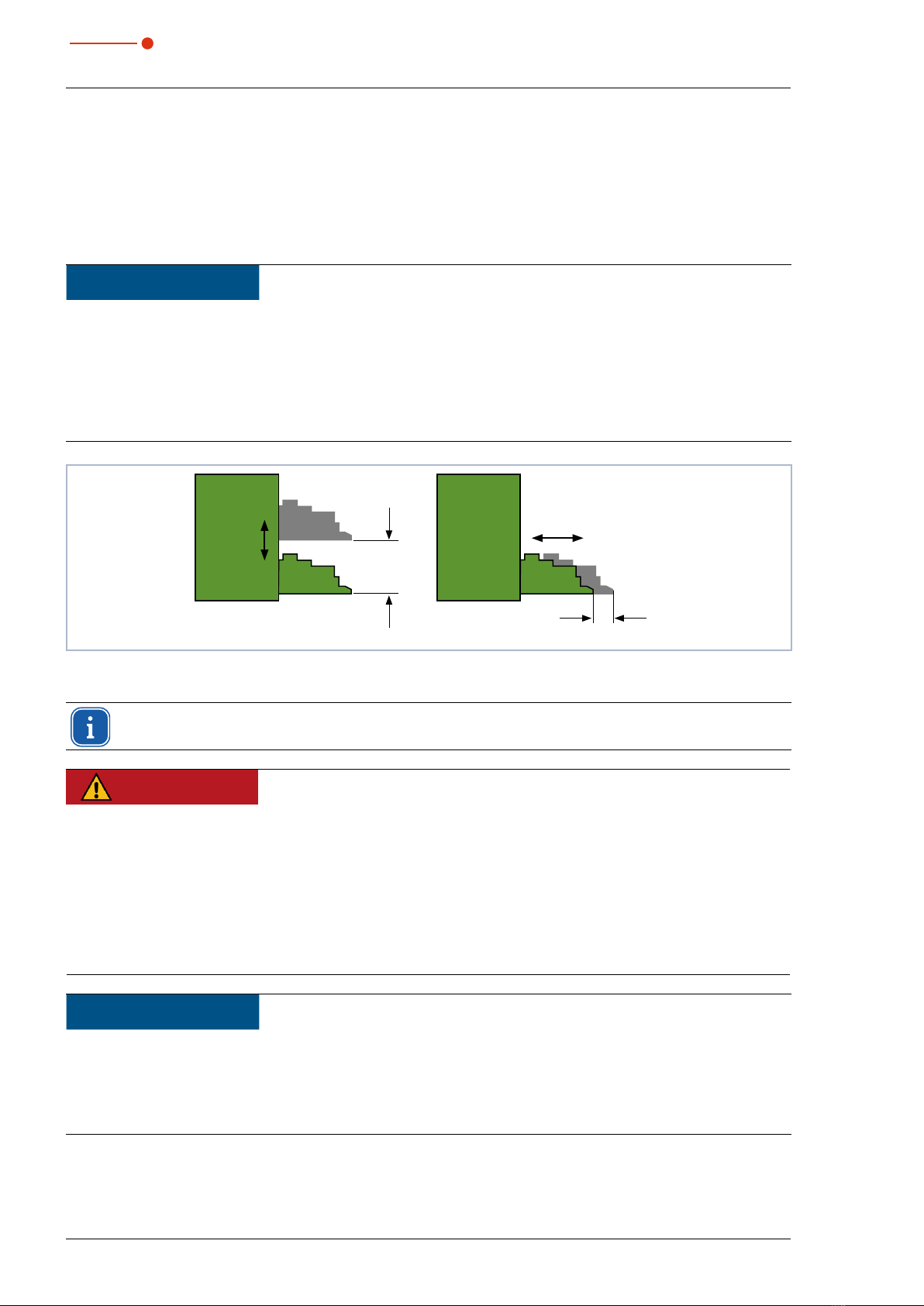
7.2 Preparation
Before installation, check the available space, especially to ensure that there is enough room for the move-
ment range of the FocusMonitorFM+.
The device must be firmly assembled and must be mounted with screws (see chapter 7.5 on page20). Its
symmetrical construction allows the device to be set up and mounted overhead without additional aids. The
position and diameter of the mounting holes on the top/bottom are identical.
NOTICE
Damage/Destruction of the device
Obstacles in the movement range of the FocusMonitorFM+ can lead to collisions and dam-
age the device.
X
Keep the movement range free of obstacles (cutting nozzle, pressure rolls, etc.).
Please note that the measuring head automatically moves into its resting position after the
power supply has been turned off and on again or following a reset. Keep this area clear.
z=120mm
y= max. 22mm
Fig. 7.3: Movement range of the measuring head
In the LaserDiagnosticsSoftwareLDS you have the option to restrict the movement range of the
FocusMonitorFM+ (locked area, for further informationen see chapter 11.4.4 on page 32).
DANGER
Fire and explosion hazards due to scattered or directed laser radiation
When the FocusMonitorFM+ is being operated, the irradiation must be fully absorbed be-
hind the measurement zone. Fire bricks or other partly-absorbing surfaces are not suitable.
X
Use an adequate absorber. Dependent on the application, PRIMES offers suitable absorbers,
such as the PowerMonitor PM48/100.
X
Don’t store any flammable materials or highly flammable substances at the measuring loca-
tion.
NOTICE
Damage/Destruction of the absorber (e. g. PowerMonitor PM48/100)
If the focused laser hits the absorber, it may be destroyed.
X
Ensure there is enough distance between the FocusMonitorFM+ and the absorber (themax-
imum permissible power density of the absorber must not be exceeded).

FocusMonitor FM+ 35,0(6
17
Revision 03/2019 EN
7.3 Installation position
You can install the device in different positions (see Fig. 7.4 on page 17). The standard position is intended
for beam incidence from above.
When accessibility is limited, you have the option of installing the device upside down with a rotated measur-
ing tip (see chapter 18.5 on page 52).
A
Upside down installation
with
turned measuring tip
Standard installation
Mounting surface
Beam incidence
Mounting surface
B
Fig. 7.4: Mounting options for the FocusMonitorFM+
To prevent transport damage, the measuring tip is disassembled when delivered. It is installed with the
curved part facing towards the beam source (see Fig. 7.5 on page 17). Further information on mounting
the measuring tip is provided in chapter 18.5 on page52.
Beam incidence
Fig. 7.5: Direction of the measuring tip during installation
The FocusMonitorFM+ can also be mounted on a vertical surface so that it can be operated with
the beam entering horizontally. Ensure that it is fastened securely in the horizontal direction.
FocusMonitor FM+
35,0(
6
18 Revision 03/2019 EN
7.4 Align the FocusMonitorFM+
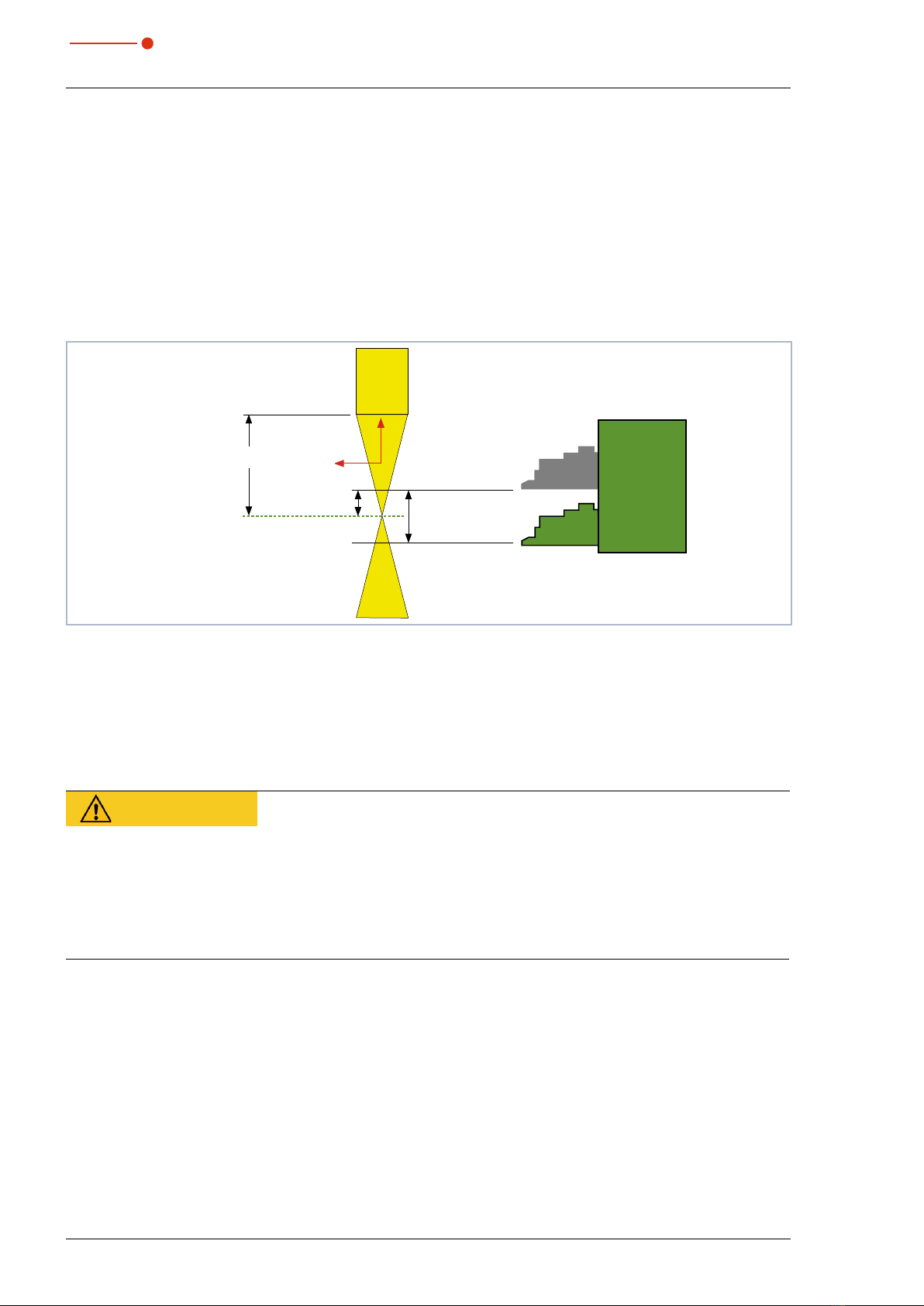
7.4.1 Device's position in relation to the laser beam
For the FocusMonitorFM+, the beam must enter vertically to the x-y-plane (see Fig. 7.6 on page 18).
The vertical alignment (z-axis) is primarily dependent on the expected focal length. The maximum vertical
stroke of the measuring device is 120mm.
The beam focus should be in the middle of the movement range of the z-axis. This is approx. 60mm above
the resting position of the measuring head (see Fig. 7.6 on page 18).
FocusMonitorFM+
Focusing
plane
60mm
Focal length f
Measuring range
120mm
z
y
Resting position
Fig. 7.6: Measuring range of FocusMonitorFM+
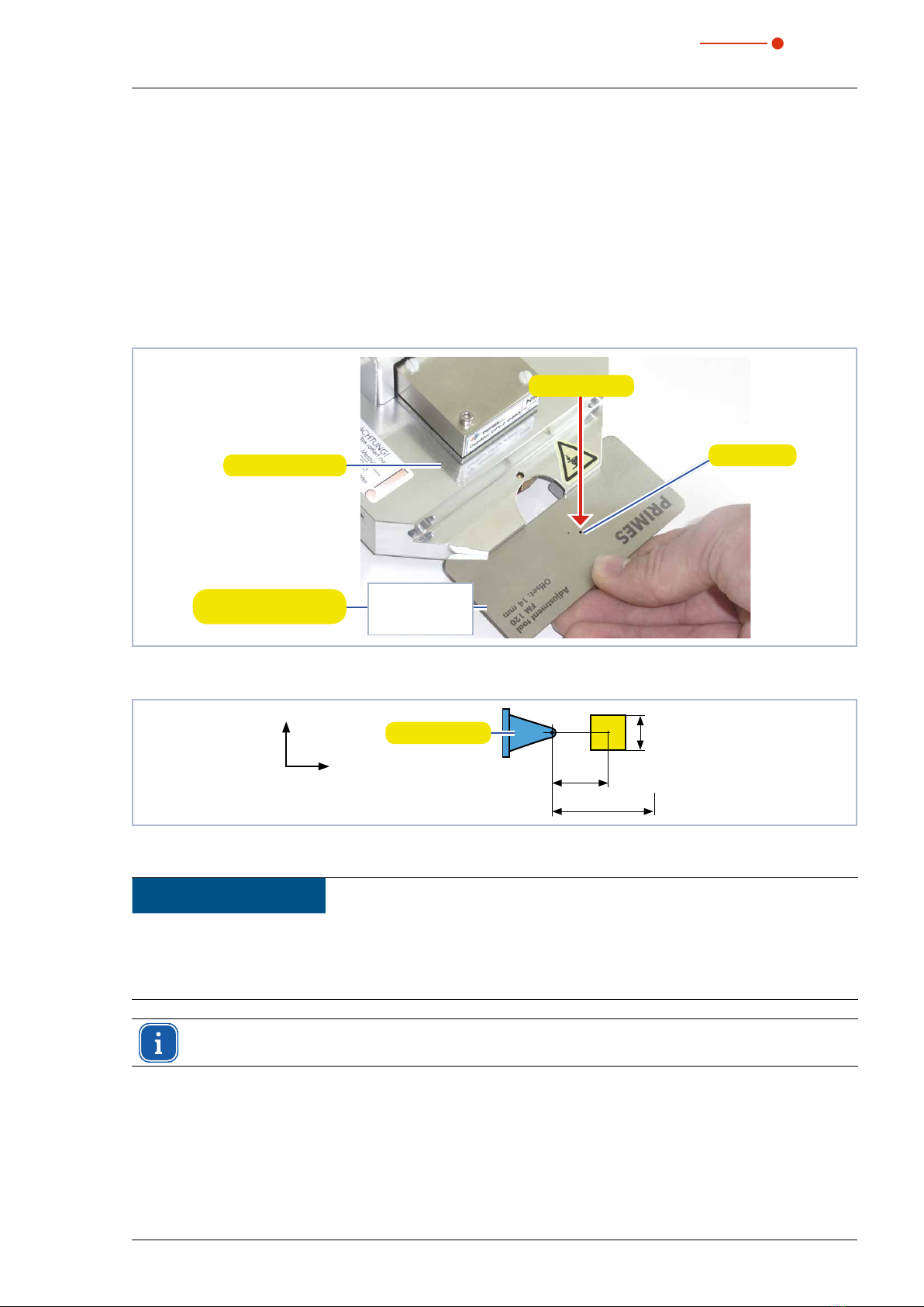
7.4.2 Align the FocusMonitorFM+ with the alignment tool
An alignment tool (see Fig. 7.7 on page 19) is provided with every device to ensure the seamless align-
ment (x-y plane) with the laser beam. The alignment tools differ depending on the size of the measuring win-
dow. The offset (distance from the aperture in the measuring tip (pinhole) in the resting position to the middle
of the measuring window in the y-direction) is given on the alignment tool (see Fig. 7.8 on page 19).
CAUTION
Risk of injury caused by rotating or moving parts
The linear movement of the horizontal and vertical carriers and the rotating measuring tip
pose an injury hazard.
X
Do not place your hand in the traversing range of the measuring head.
X
Only align the FocusMonitorFM+ while the measuring tip is stationary.
FocusMonitor FM+ 35,0(6
19
Revision 03/2019 EN
1. Connect the FocusMonitorFM+ with the LaserDiagnosticsSoftware LDS as described in chapter 11.3 on
page 28.
2. Choose the function of the FocusMonitorFM+ as described in chapter 11.4.1 on page 29.
3. In accordance with chapter 11.4.3 on page 31, enter the value of 60mm in the Device Control >
Advanced > Move axes menu.
• The horizontal carrier will move to the position 60mm above its resting position (see Fig. 7.6 on page 18)
without a rotated measuring tip.
4. Place the alignment tool on the measuring head.
5. Turn on the pilot laser and align the device:
• If the laser beam hits perpendicular to and in the middle of the small marking in the alignment tool, the
device is properly aligned.
Pilot beam
Measuring head
Alignment tool with the
offset specified
Marking
Adjustment tool
FM 120
Offset: 14mm
Fig. 7.7: Alignment tool at the measuring head of FocusMonitorFM+
y-axis
x-axis
Offset = 14mm
max. 22mm
8 x 8mm
Measuring tip
Fig. 7.8: Offset of a measurement window size of 8 x 8mm
NOTICE
Damage/destruction of the alignment tool
The exposure with laser radiation will destroy the alignment tool.
X
Remove the alignment tool before turning on the laser.
Five to twelve seconds after the supply voltage is switched on, the FocusMonitorFM+ moves into
the resting position (lowest z-position).
FocusMonitor FM+
35,0(
6
20 Revision 03/2019 EN
7.5 Install the FocusMonitorFM+
DANGER
Serious eye or skin injury due to laser radiation
If the device is moved from its calibrated position, increased scattered or directed reflection
of the laser beam occurs during measuring operation (laser class 4).
X
Mount the device so that it cannot be moved by an unintentional knock or cables being
pulled accidentally.
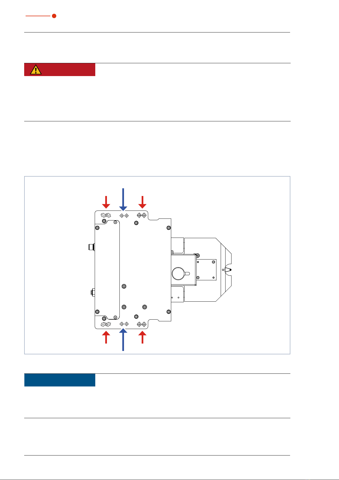
The mounting surface of the housing has six slotted holes Ø6.4mm and four alignment holes Ø6G7mm for
assembly on a support bracket provided by the customer (see Fig. 7.9 on page 20).
Use at least four M6screws to fasten the housing.
The total length of the screws depends on the dimensions of the customer’s support bracket.
The dimensioned arrangement of the mounting holes is specified in chapter17, „Dimensions“, on
page44.
Slotted holes Ø6.4mm
Alignment holes Ø6G7mm
Fig. 7.9: Mounting holes, view from above (same hole pattern below)
NOTICE
Damage/Destruction of the measuring tip
If the laser beam hits the measuring tip in the beam path, it could be destroyed.
X
Remove the measuring tip from the beam path following installation.
Other manuals for FocusMonitor FM+
1
Table of contents
Other Primes Diagnostic Equipment manuals


