Display Specifications
Table 2: 14000 Transmitter Display Specifications
Component Description
Time Displays the precise time received from the GPS Receiver.
If AM or PM is on the display, then the 12-hour option is selected.
If neither AM nor PM is on the display, then the 24-hour option is selected.
Daylight Saving Time The letters "DT" (Daylight Saving Time) or "ST" (Standard Time) will be displayed
when adjustment for Daylight Saving Time is active.
If neither "DT" nor "ST" is displayed, then switch #3 is in the down position and the
transmitter will not adjust for Daylight Saving Time.
GPS Communication The GPS Communication indicator appears when the transmitter is
communicating with the GPS Receiver.
The parentheses indicate the time signal is being received.
Day/Date Displays the day and date received from the GPS satellite.
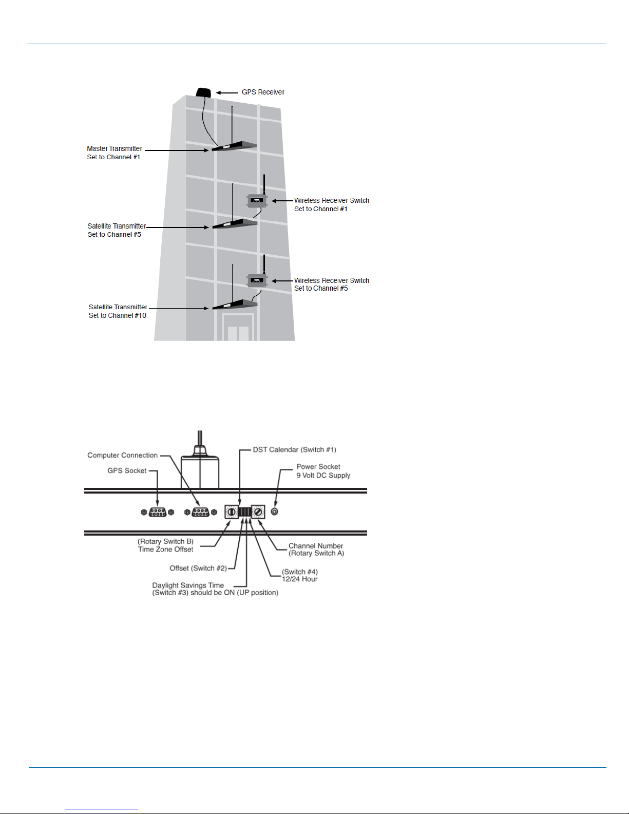
Channel Number Displays the channel number (1-16) the transmitter is set to.
Red LED The red LED (Light Emitting Diode) is located on the right side of the front panel of
the transmitter.
The LED flashes on initial setup until a GPS time signal is received or when a
severe GPS Receiver signal problem has occurred and no time data has been
received from the GPS Receiver in 48 hours.
See the Troubleshooting section of this guide for additional information.
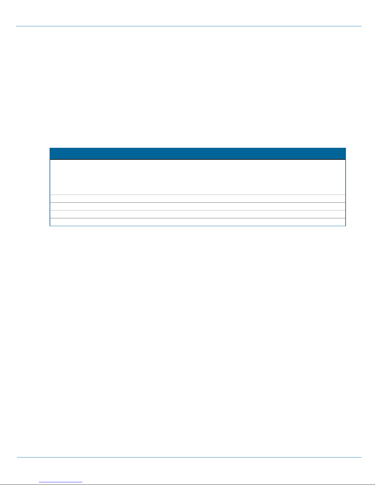
Receiver Switch Specifications
Included with Satellite Transmitter.
Table 3: Receiver Switch Specifications
Component Description
Cable 5' (1.52m) RS232 cable connects Receiver Switch to the Satellite Transmitter.
Dimensions 5.75" (14.6cm) L x 4.25" (10.8cm) H x 1.25" (3.16cm) D
Antenna 12.5" (31.75cm) L
Weight 0.75 lb (.34kg)
Power Supply Input: 120 VAC, 50/60 Hz, 0.4 Amp
Output: 9 VDC, 0.25 Amp, 6' (1.83m) cord
Operating Range -32° - 158° F (-36° - 70° C)
Primex Wireless 14000 Series Satellite Transmitter Installation & User Guide 4
System Specifications Transmitter Display Specifications