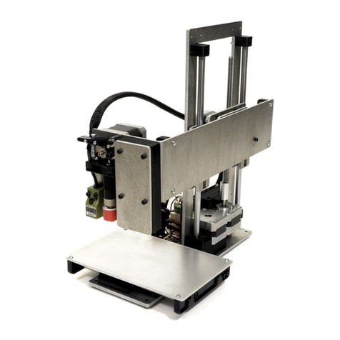
Printrbot Play 1505 User manual

Step 1 — What's in the box
Congratulations on receiving your new Printrbot Play kit! Before beginning the build, look
over the checklist of materials and tools to make the experience as hassle free as
possible.
Tools - Take a look at the top of this guide for a list of tools needed for the build. We
have included some, but you will need to supply a couple of your own as well.
BOM - Review the Bill of Materials and check it against what you received in your
package. If anything is missing, please contact us at Printrbot.com/Support
Docs - If you are having a hard time with any of the example photos in the steps, you may
prefer the exploded view docs attached to the top of this guide. There are also some great
files/downloads/videos at Printrbot.com/project/play
Vids - If you would prefer to follow a build video, click here for a series of build videos
contributed by Warrior Poet Training.
Assembling the Printrbot Play Kit (Model 1505)
© 2015 help.printrbot.com Page 2 of 29

Step 2 — Installing Y Axis Bearings
Place the 8mm linear bearings (x3) into the bearing slot cutouts on top of base.
Insert Delrin bearing clamps (x3). Insert the two pointed ends of the clamps through the
base then rotate the clamps to capture the bearings.
Fasten bearings with M3 8mm (x6) - Two screws per clamp.
Maker to Play Upgrade Users: Before disassembling your existing bot, be sure that you
have printed the parts that you will need for this build. CLICK HERE for printable files.
Step 3 — Assembling Y Axis Idler Pulley
Press one 624 bearing into a delrin pulley half. Then, repeat this step to make a second
pressed bearing/pulley.
Insert an M4 22mm screw through the 624 bearing/delrin pulley assembly.
Add 1/8" nylon spacer to the screw, and then the second bearing/pulley.
NOTE: The thinner sides of the delrin pulleys should be facing inward, towards each other
in the stack and the 1/8" nylon spacer should not be visible once this stack has been
assembled.
Assembling the Printrbot Play Kit (Model 1505)
© 2015 help.printrbot.com Page 3 of 29

Step 4 — Installing Y Axis Idler Pulley
Screw your assembled M4 22mm/bearing/pulley stack into the base with a 3mm Allen hex
key.
Use your 1.5mm Allen hex key to attach the end stop with the short wires to the base with
M2 10mm screws (x2). The metal switch of the end stop should be oriented to the outside
of the base, away from the bearing.
NOTE: Be sure to use the end stop with the shortest wires.
TIP: This will be your "Y axis end stop" It is a good idea to mark the white plastic
connector on with a "Y". This will make things easier when it is time to wire the
Printrboard.
Assembling the Printrbot Play Kit (Model 1505)
© 2015 help.printrbot.com Page 4 of 29

Step 5 — Installing Y Axis Motor / Pulley
Pick any motor and attach a GT2 pulley to the motor shaft with M3 set screws (x2). Be
sure that one of the set screws threads down on to the flat side of the motor shaft. Note
that the GT2 pulley is oriented with the flanges away from the body of the motor.
Adjust the height of the GT2 pulley on motor to align with the delrin pulley/bearing stack
assembled earlier.
Once you have found the correct GT2 pulley alignment, use Threadlocker to secure the set
screws on to the motor shaft.
Face the motor wire leads toward the Y axis end stop.
Attach the motor to the base with M3 16mm screws (x3).
TIP: This will be your "Y axis motor". Take a moment to label the plastic connector on this
motor with a "Y".
Assembling the Printrbot Play Kit (Model 1505)
© 2015 help.printrbot.com Page 5 of 29

Step 6 — Installing Z Axis Bar End Supports
Find two of the Delrin Z rod supports and #4-20 3/8” plastite screws (x6).
TIP: To identify the "plastite screws", ignore the screw head type and focus on the thread
type. The plastite screw threading is wider and more angled.
Install the Z axis bar ends (x2) onto both sides of the base with #4-20 3/8” plastite screws
(x3 each).
Step 7 — Installing Z Axis Motor
Mount your Printrboard with M3 6mm screws (x4). Make sure the USB and SD Card slots
are facing towards the opening.
Attach a motor with wire leads facing board using M3 6mm screws (x4).
TIP: This will be your "Z axis motor". Take a moment to label the plastic connector on this
motor with a "Z".
Assembling the Printrbot Play Kit (Model 1505)
© 2015 help.printrbot.com Page 6 of 29

Step 8 — Attach Leadscrew to Z Motor
Secure your 1/4" acme coupler to the Z axis stepper shaft approximately 7mm up from
base plate with an M3 set screw.
TIP: You can use a couple of belt tensioner clips as a spacer for the coupler height.
Insert 1/4”-16 acme rod into the other end of coupler and secure into place with an M3 set
screw.
NOTE: If the coupler is too low on the motor shaft the set screws will not bite into the
acme rod. The set screw will seat itself into the threads on the acme rod as it is tightened.
Try lifting up on the threaded rod to make sure it has been secured by the set screw.
REMINDER: Use Threadlocker on your set screws once the coupler is in place.
Step 9 — Insert Z Smooth Rods
Gently tap 250mm 8mm smooth
rods (x2) into the pockets of the Z
axis bar ends (previously
installed).
NOTE: Make sure bars are seated
fully into the bar end pockets.
Click here for a video
demonstration of using a mallet to
insert the Z axis smooth rods into
the Z bar ends.
Assembling the Printrbot Play Kit (Model 1505)
© 2015 help.printrbot.com Page 7 of 29

Step 10 — Installing X Motor / Pulley
Attach a GT2 pulley onto the shaft of an unused motor with M3 set screws (x2). Again, the
GT2 pulley should be oriented with the set screws closer to the body of the motor. Leave
approximately 3mm of space between the pulley and the body of the motor on the motor
shaft.
Attach the motor to the XZ carriage plate with M3 6mm screws (x2). Note that motor is
oriented with the wiring directed away from the XZ carriage plate.
TIP: This will be your "X axis motor". Take a moment to label the plastic connector on this
motor with a "X".
Step 11 — Installing Z Axis Delrin Nut
Install the delrin nut with an M3 30mm phillips head screw and plastite screw.
The M3 30mm screw goes through the nut and screws into the stepper motor.
Assembling the Printrbot Play Kit (Model 1505)
© 2015 help.printrbot.com Page 8 of 29

Step 12 — Installing X Carriage Bearings
Install 8mm bearings (x2) with bearing clamps onto the motor end of the XZ plate using M3
8mm screws (x2 each).
Install one more 8mm bearing with a bearing clamp onto the opposite end with M3 8mm
screws (x2).
Click here for a video demonstration of installing the 8mm bearings for the Z axis.
Step 13 — Install X Axis Idler Pulley
Press two 624 bearings into two Delrin pulley halves.
Place 1/8” nylon spacer between the bearing/pulley.
Insert an M4 20mm screw through the pulley assembly.
Add an M4 washer to this screw/bearing/pulley "stack", and screw the assembly into the
XZ carriage plate. This stack will attach to the end of the carriage without the X axis motor.
Assembling the Printrbot Play Kit (Model 1505)
© 2015 help.printrbot.com Page 9 of 29

Step 14 — XZ Carriage Smooth Rod Installation
Place an 8mm linear bearing onto a 250mm smooth rod. Repeat this step.
Seat 250mm the smooth rods w/ bearings (x2) into matching slots of the XZ plate. Rods
should be on same side as the X axis motor (opposite side of X idler pulley).
Use plastite screws (x2 each) to attach X axis bar clamps onto the bar ends and secure
the bars to the XZ carriage plate.
Step 15
NOTE: If you received a rod clamp with a corner cut, it is meant to be installed adjacent to
the pulley, to allow the pulley to spin freely.
Assembling the Printrbot Play Kit (Model 1505)
© 2015 help.printrbot.com Page 10 of 29

Step 16 — Installing XZ 4th Bearing
A fourth 8mm bearing can now be installed and secured into the remaining bearing hole on
the XZ carriage. Use plastite screws (x2) to secure the bearing clamp to the bar end on.
TIP: Use one of your remaining 8mm rods to make sure bearing alignment is correct. If
bearings do not move freely loosen bearing holder screws and re-tighten. Bar clamps
should be snug and not rattle while linear bearings should slide smoothly.
Attach the 28” end stop to the XZ carriage with M2.5 10mm screws (x2).
NOTE: The end stop switch should open towards the middle of the XZ carriage plate, with
the "gator mouth" open towards the X axis motor.
Step 17 — Install Wire Relief and Position Extruder Cart
Attach the delrin wire relief onto the extruder cart using M3 6mm screws (x2). Note that
the single hole on the wire relief should be oriented to the top after the delrin piece has
been screwed to the carriage.
Insert the extruder cart horizontally between the middle bar of the carriage plate and the
upper smooth rod. Next, twist the carriage vertically until bearings match up with bearing
cutouts.
Assembling the Printrbot Play Kit (Model 1505)
© 2015 help.printrbot.com Page 11 of 29

Step 18 — Attaching X Axis Bearing Brace
Place the flat portion of X axis bearing clamp away from the arm of the the X cart. Notice
the orientation of clamp to the extruder cart. The clamp should mimic the shape of the
carriage, stair-stepping to the right.
Secure the X axis bearing clamp to extruder card using M3 25mm screws (x4).
TIP: Tighten each screw evenly a little bit at a time alternating between the 4 screws until
all are tight.
Step 19 — Install X Axis Belt Tensioner
Thread the 500mm belt (longer belt) through the 2 holes in the belt tensioner as shown. Zip
tie close to the tensioner, lastly cut off excess plastic tie.
Place M3 40mm screws (x2) through the matching holes in the extruder carriage and
thread them just slightly into the belt tensioner to get started. Make sure that the nub of the
zip tie is facing down, towards the bottom side of the extruder assembly.
Assembling the Printrbot Play Kit (Model 1505)
© 2015 help.printrbot.com Page 12 of 29

Step 20 — X Axis Belt Part 1
Wrap the belt around X axis idler pulley.
Next, route the belt around the GT2 pulley, aligning the teeth of the belt with the grooves of
the pulley.
Assembling the Printrbot Play Kit (Model 1505)
© 2015 help.printrbot.com Page 13 of 29

Step 21 — X Axis Belt Part 2
Using needle nose pliers, feed belt back towards extruder cart and through belt slots in
extruder cart. Pull tight by hand to remove slack for now.
Keeping the X belt tight, secure the now threaded belt end with a zip tie. Before tightening
the zip tie, align the teeth of the GT2 belt against the grooves of the belt.
NOTE: Secure the zip tie as close to the extruder cart as possible. Also, make sure the
nub of the zip tie is pointing away from the carriage. Failure to do so could cause the nub
to hit the Z axis delrin nut when the printer is in use.
Tighten the belt further by turning the tensioner screws.
Cut off extra belt length as close to zip ties as possible to prevent it from interfering with
the motor pulley.
Assembling the Printrbot Play Kit (Model 1505)
© 2015 help.printrbot.com Page 14 of 29

Step 22 — Install Extruder Gear
Attach a motor to the extruder carriage with an M3 6mm screw. Only attach the left side of
the base for now leaving the right hole empty.
Attach the extruder base to the carriage, using an M3 25mm screw, to the bottom left
screw hole.
TIP: This will be your "extruder motor". Take a moment to label the plastic connector on
this motor with a "E".
Step 23 — Preparing Extruder Arm
Thread an M3 30mm philips head screw through hole in extruder arm. Add the extruder
spring onto screw and secure with an M3 hex nut.
Place a 624 bearing into bearing slot on extruder arm. Secure with an M4 12mm screw.
Insert the extruder arm post into the post hole of extruder arm. The flange of the insert
should be on the inside and face the extruder motor. Thread an M3 30mm screw and M4
washer through the extruder arm.
Assembling the Printrbot Play Kit (Model 1505)
© 2015 help.printrbot.com Page 15 of 29

Step 24 — Install Extruder Arm
Attach the drive gear to the extruder motor by tightening an M3 set screw down on to the
flat side of the shaft. Make sure the serrated portion of the extruder gear lines up with the
ridge of the extruder base. Take set screw and dip in thread locker and secure the drive
gear onto the motor shaft with set screw
REMINDER: Once the drive gear is aligned, use Threadlocker to secure the set screw on
to the motor shaft.
Place end of spring / screw assembly of extruder arm into matching hole of the extruder
base.
Secure extruder arm pivot by threading an M3 25mm screw through extruder cart into
extruder motor.
Assembling the Printrbot Play Kit (Model 1505)
© 2015 help.printrbot.com Page 16 of 29

Step 25 — Installing Hot end
Loosen the M3 25mm screw to allow room to feed thermistor and power cables through the
cable retention notch on extruder carriage.
Secure extruder base again making sure no wires are pinched.
White/black cable extension goes to clear wired connector on the hot end. Black/red wiring
cable extension connects to black wired connector on hot end.
Attach extension cables as advised in previous step.
Press hot end into matching hole on extruder base, press the hot end all the way in so that
it is flush with the aluminum. Secure hot end by inserting and securing (1) M3 25mm screw
into remaining hole of extruder base.
Assembling the Printrbot Play Kit (Model 1505)
© 2015 help.printrbot.com Page 17 of 29

Step 26 — Attaching Sensor Probe
Remove all extra nuts and washers from the Auto-Leveling Probe.
Use an M3 6mm screw to attach the delrin sensor clamp to the XZ carriage plate.
Wrap the sensor clamp around the probe, and secure the Auto-Leveling Probe within the
sensor probe clamp using the M3 16mm screw. Tighten until the probe is secure.
Step 27 — Extruder Wiring
Tighten a zip tie around the extruder assembly wiring. Any connectors (probe, hot end
thermistor, power, etc) should be above the zip tie.
Compress the wire wrap and work the wiring through the wire wrap.
Assembling the Printrbot Play Kit (Model 1505)
© 2015 help.printrbot.com Page 18 of 29

Step 28 — Secure Extruder Wire Braiding
Secure the extruder assembly wiring against the wire relief with a zip tie.
Use another zip tie to manage the wiring for the X axis motor wiring.
Step 29
Bend the wires in middle and pull all wires together through second wire wrap.
Stretch out the wrap to its full length and zip-tie at the far end.
Assembling the Printrbot Play Kit (Model 1505)
© 2015 help.printrbot.com Page 19 of 29

Step 30 — Attach Fans to Extruder Cover
Attach two fans to the extruder fan shroud with plastite screws (x2 each).
NOTE: Be sure to place the fan with the black 3-pin connector in the top position. This fan
will provide constant air to your hot end when the bot is powered on.
Note that the fan wires are directed to the top of the fan shroud and the stickers for the fan
are facing away from the front of the fan shroud.
Step 31 — Attach Top Z Axis Bar Ends
Use plastite screws (x3 each) to attach the two remaining Z bar ends to the top base metal
part.
TIP: The pockets in the bar ends should face the bottom of the machine so that they can
accept the smooth rod ends.
Assembling the Printrbot Play Kit (Model 1505)
© 2015 help.printrbot.com Page 20 of 29
This manual suits for next models
1
Other Printrbot 3D Printer manuals

