Pro-face PS3710A-T42 User manual
1
PS-3710A Series
Installation Guide
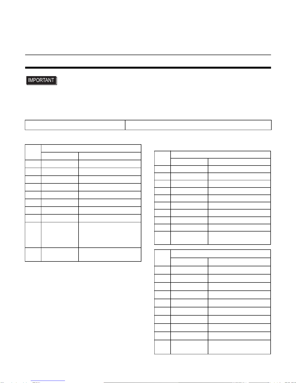
Package Contents
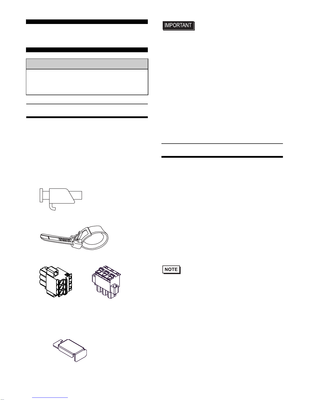
(1) PS-A Unit (1)
(2) English and Japanese Installation Guides
(one of each) <This Guide>
(3) Warning/Caution Information (1)
(4) Installation Gasket (1) (attached to the
PS-A unit)
(5) Installation Fasteners (Set of 4 x 2)
(6) USB Cable Clamp (2 ports) (2)
(7) Power Plug (1)
(8) Power Switch cover (cover:1, secrew:1)
(AC type Only)
• Be careful when installing the PS-A not
to damage the built-in HDD.
This unit has been carefully packed, with
special attention to quality. However, should
you find anything damaged or missing,
please contact your local PS-A distributor
immediately.
When you order a PS-A unit built to your
specifications, that PS-A package should
include each optional item's Installation
Guide. Please use that guide to check the
contents of each optional item's package.
About the Manual
For detailed information on PS-A series, refer
to the following manuals.
• PS-3710A/PS-3711A Series Hardware
Manual
• PS-3710A/PS-3711A Series Refer-
ence Manual
• API Reference Manual
Manual can be downloaded from Pro-face
Home Page.
URL
http://www.pro-face.com/otasuke/
• The drivers and utilities for PS-A can be
downloaded from Pro-face Home Page.
Caution
Be sure to read the “Warning/Caution
Information” on the attached sheet before
using the product.
AC type
(5.08mm pitch) DC type
(7.62mm pitch)
2
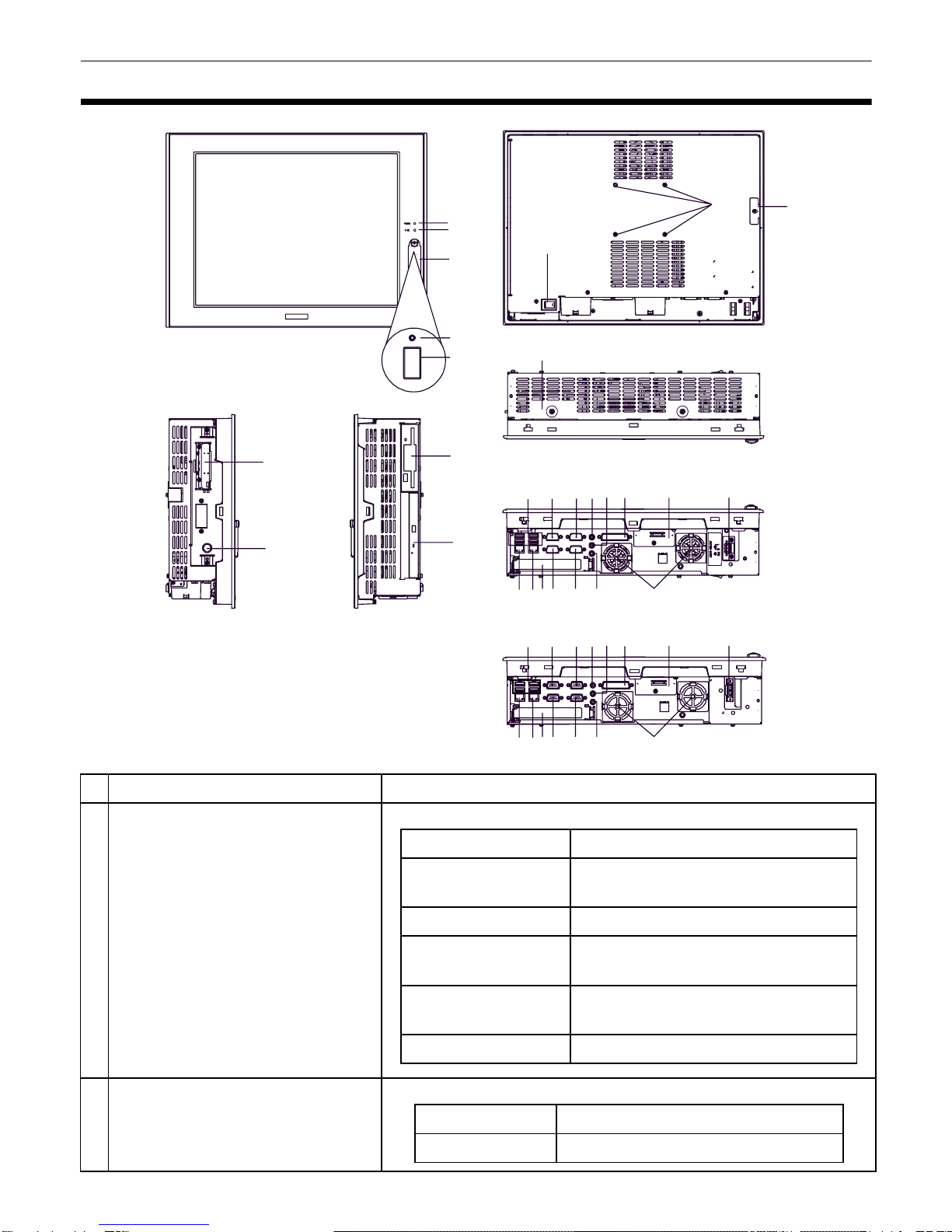
Part Names and Functions
Name Description
APower LED / RAS Status
Lamp (POWER)
B IDE Access Lamp
Front Rear
A
B
C
F
E
D
I
Left Side
H
G
J
KTop
Right Side
L
M
N
TR
X
V
W
O
1
Bottom
ZP
S
Q
UY 2
PS3710A-T42
NXW 1SUY 2
TR VOZPQ PS3710A-T42-24V
LED PS-A Status
Green (lit) Normal Operation
(power is on)
Green (blinking) Soft OFF state
Orange (lit) System Monitor Error
Touch Panel Self Test Error
Orange/Red
(blinking) Backlight burnout is detected
Not lit Power is OFF
LED PS-A Status
Green (lit) Currently using IDE I/F
3
C Front Cover
-
D
Hardware Reset Switch (RESET)
Used to restart PS-A.
E USB Interface (USB)
1 port. Complies with USB 2.0. Uses a “TYPE-A” connector.
F Arm Insertion Hole Location VESA 75mm
G Power Switch Supported by AC type (PS3710A-T42) only.
H Expansion Board Support
-
I FD Drive
-
JDVDDrive
-
K PCMCIA Interface (PCMCIA) 2 ports. PCMCIA Type II, Type III can be available.
Corresponding to CARD BUS (Excluding VIDEO
ZOOM, SOUND functions)
LPS/2 Keyboard Interface
(KEYBOARD) A mini DIN 6 pin (socket) is used.
M Rear Cover
-
N USB Interface (USB)
4 ports. Complies with USB 2.0.Uses a “TYPE-A” connector.
O Ethernet Interface (LAN1) 10BASE-T/100BASE-TX Auto Changeover.
This interface uses an RJ-45 type modular jack
connector (8 pins).
P Ethernet Interface (LAN2)
10BASE-T/100BASE-TX/1000BASE-T Auto Changeover.
This interface uses an RJ-45 type modular jack connector
(8 pins).
Q Expansion Unit Interface 1 port. Used to attach the PCI Unit.
R Serial Interface (COM1) D-SUB 9-pin plug type. RS-232C, RI/+5V Changeover.
S Serial Interface (COM2) D-SUB 9-pin plug type. RS-232C, RI/+5V Changeover.
T Serial Interface (COM3) D-SUB 9-pin plug type. RS-232C, RS-422, RS-485
Changeover.
U Serial Interface (COM4) D-SUB 9-pin plug type. RS-232C.
Changes the Touch Panel communication method.
(Serial <---> USB)
Power supply voltage DC 5V ±5%
Output current Each port:500mA(max.),
5 ports total:500mA(max.)
The maximum
communication distance
5m
Power supply voltage DC 5V ±5%
Output current Each port:500mA(max.),
5 ports total:500mA(max.)
The maximum
communication distance
5m

4
• When attaching peripheral units to the PS-A, be sure the PS-A's power cord is dis-
connected from the main power supply.
General Specifications
Electrical Specifications
Environmental Specifications
V Line Input Interface (LINE IN)
3 ports. (standard type AUDIO jack)WSpeaker Output Interface
(SPEAKER OUT)
X Mike Input Interface (MIC IN)
Y RAS Interface (RAS) D-SUB 25-pin plug type.
Z Cooling FAN
-
1 CF Card Interface Cover CF card interface is under the cover. Type II-compliant
slot. IDE-type connection.*1
CF card (Type I / II-compliant) is available.
2 Power Connector
-
*1 Since an IDE-type connection is used, the unit is not hot-swappable. When inserting/removing the
CF card, be sure that power is turned OFF.
PS3710A-T42 PS3710A-T42-24V
Power Supply
Input Voltage AC100/240V DC24V
Rated Voltage AC85 to 265V DC19.2 to 28.8V
Rated Frequency 50/60Hz
-
Allowable Voltage Drop
1 cycle or less (Voltage drop
interval must be 1s or more.) 5ms or less
Power
Consumption 150VA or less 110W or less
Voltage Endurance AC1,500V
20mA for 1minute
(between charging and FG
terminals)
AC1,000V
20mA for 1 minute
(between charging and FG
terminals)
Insulation Resistance DC500V 10MΩ(min.) (between charging and FG terminals)
Physical
Surrounding Air
Temperature 0 to
50°C
: without HDD
5 to
50°C
: with HDD
Storage Temperature -20 to +60°C
Ambient Humidity
10 to 90% RH (Not condensing, wet bulb temperature: 29°C or less. )
Storage Humidity
10 to 90% RH (Not condensing, wet bulb temperature:29°C or less.)
Dust Free of dust
Pollution Degree For use in Pollution Degree 2 environment

5
• When using any of the PS-A’s optional devices, be sure to check that device’s speci-
fications for any special conditions or cautions that may apply to its use.
• Be aware that not only does the Hard Disk have a fixed lifetime, but that accidents
can always occur. Therefore, be sure to back up your Hard Disk’s data regularly, or
prepare another Hard Disk unit that can be used for backup.
• The Hard Disk lifetime given here may be reduced due to unforeseen environmental
factors, however, generally speaking, the disk should last for 20,000 hours (of opera-
tion) or approximately 5 years, whichever comes first, at an operating temperature of
20°C and 333 hours of operation per month. (HDD access frequency of 20% or less)
• Using the Hard Disk in an environment that is excessively hot and/or humid will
shorten the disk’s usage lifetime. A wet bulb temperature of 29°C or less is recom-
mended. This is equivalent to the following data.
• In order to extend the lifetime of the hard disk, Pro-face recommends you set the Win-
dows
®
2000 or XP (classic) [Control panel]-[Power Options]-
[Power Options Proper-
ties]-[Power Schemes]-
[Turn off hard disks] selection to turn the hard disk off when the
unit is not being operated. A setting of 5 minutes is recommended.
Switches
The following switch settings corresponding to Serial Interfaces and some system features need
to be signified. To set the switches which are on the PS-A’s circuit board, remove the PS-A’s Rear
Cover. Please refer to "Installations", "4.Removal/Attachment the Rear Cover".
Temperature at 35°C at 40°C
Humidity no higher than 64% RH no higher than 44% RH
Switch
Location
Switch Name Compatible
I/F Factory
Settings Description
ASerial Mode Select
SW COM3
All OFF
(RS-232C)
10-point dip switch. Designates COM3
communication settings. For Serial Mode
Select SW details, see Table (2).
B System Set SW - See
Table (1) 10-point dip switch. For System Set SW and
the factory settings details, see Table (1).
ON
123456789
10 10
ON
123456789
RI
AB
CD
E
5V RI 5V
USB RS232C
Inside of the rear
Switch Locations
6
CRI/+5V Changeover
SW COM1 RI Changes # 9 pin (RI <---> +5V).
DRI/+5V
Changeover SW COM2 RI Changes # 9 pin (RI <---> +5V).
ETouch Panel's
Communication
Changeover SW
COM4
USB USB
Changes the Touch Panel
communication method. (Serial <--->
USB) (If "Serial" is selected, COM4
cannot be used.)
Switch
Location
Switch Name Compatible
I/F Factory
Settings Description
Switch
No.
Description ON OFF
Factory
Settings Notes
1Cancellation function of
pushing two points on
the touch panel*1.
*1 When two points are pushed, it is considered that middle point between the two points is touched
according to the nature of the analog resistive touch panel.
When the switch, etc. is set on the middle point, it will be enabled and may operate.
To prevent such a switch from malfunction in case of pushing two points, turn ON the SW No.1 in
advance, then the middle point will be disabled to be touched.
Enabled Disabled OFF
The middle point is not
considered to be touched when
the SW is ON. It is considered to
be touched when the SW is
OFF.
2
Changes PIO/DMA of
CF Card.
PIO+DMA PIO ON
3
Changes PIO/DMA of
CF Card.
PIO+DMA PIO ON
4
Sets up an enabled/
disabled state for the
port execution control
function of hardware
reset switch.
Disabled Enabled OFF
The hardware reset switch is
unavailable when the SW is
ON. But, it is available to enter
switch from the Soft OFF*2
state.
5
Able to change a
Master/Slave setting for
CF Card slot. Master Slave OFF*3
6
Sets up an enabled/
disabled state for the
frontUSBportexecution
control function.*4 Enabled Disabled OFF
The front USB port is available
when the SW is ON. It is
unavailable when the SW is
OFF.
7
Used for the system. Reserved Reserved OFF
8
Used for the system. Reserved Reserved ON
9
Implements the logical
inversion operation for
RAS output.
Normal
Close Normal
Open OFF
RAS output is a CLOSE state
when the SW and the system is
ON. When the SW is OFF, it is the
opposite. The RAS Output keeps
Normal OPEN when the Soft
OFF
*2
state occurs or the power
turns OFF.
10
Used for the system. Reserved Reserved OFF
Table 1) System Set Switch

7
*2 The Soft OFF refers to the state that Windows®has been shut down and the power is provided only
for the electric circuit to boot system. This Soft OFF State is different from what is System Standby
set by Windows®.
*3 When built in Pro-face's Windows®XP Embedded, the factory setting is ON.
*4 The Setting up an enabled/Disabled state for USB port execution control function is available for only
Windows
®
2000 and Windows
®
XP. Make sure to disable the function of the setting when other OS used.
Switch
No. Description ON OFF
RS-232C
RS-422 RS-485
1 Used by the system. No Connection No Connection OFF
*1
*1 Be sure to keep the settings, "OFF".
OFF
*1
OFF
*1
2Changes
COM3
's
communication
method. RS-422/RS-485 RS-232C OFF ON ON
3Changes
COM3
's
communication
method. RS-422/RS-485 RS-232C OFF ON ON
4Changes TX data's
output mode. TX data output is
controlled via the
RTS signal.
TX data output is
NOT controlled via
the RTS signal.
(normally output) OFF ON/OFF ON/
OFF
*2
5Switches the TX
termination resistance
ON/OFF.
Inserts termination
resistance of 220W
between TXA and
TXB. No termination OFF ON ON/
OFF
*3
6Switches the RX
termination resistance
ON/OFF.
Inserts termination
resistance of 220W
between RXA and
RXB. No termination OFF ON ON/
OFF
*3
7Switches the shorting
of TXA and RXA ON or
OFF.
Shorts TXA and
RXA
(RS-485 mode) No shorting
(RS-422 mode) OFF OFF ON
8Switches the shorting
of TXB and RXB ON or
OFF
Shorts TXB and
RXB
(RS-485 mode) No shorting
(RS-422 mode) OFF OFF ON
9RTS Automatic control
mode
(enabled only when
RS-485 mode).
The data is
automatically
controlled via the
RTS signal.
The data is not
automatically
controlled via the
RTS signal.
OFF OFF ON/
OFF
*2
10 OFF OFF ON/
OFF
*2
Table 2) Serial Mode Select Switch
Serial Mode Select Switches (SW4 to SW10) operate as shown in the circuit diagram below.
RTS Automatic
control
8
External Interfaces
• Always connect the #5 SG (Signal Ground) of the PS-A unit to the connected device,
especially if the connected device is also not isolated. Failure to do so may damage
the RS-232C/RS-422/RS-485 circuit.
Serial Interface (COM1, COM2, COM3, COM4)
COM1, COM2, COM4
COM3
COM3 can be changed to either RS-232C,
RS-422 or RS-485. (The factory setting is
RS-232C.) To change this setting, open the
PS-A unit's rear cover and set slide switch on
the circuit board to the desired position.
Please refer to "Switches" for details.
*2 To enable RTS automatic control of the TX output driver, set SW No. 9 and 10 ON, and set SW No.4
OFF.
To enable control of the TX output driver via RTS signals, set SW No. 9 and 10 OFF, and set SW
No.4 ON
*3 If you use the termination resistance, base your settings on the connection specifications.
Interfit Bracket #4-40 (UNC)
Pin # RS-232C
Signal Name
Description
1 CD Carrier Detect
2 RD(RXD) Receive Data
3 SD(TXD) Send Data
4 ER(DTR) Data Terminal Ready
5 GND Signal Ground
6 DR(DSR) Data Set Ready
7 RS(RTS) Request to Send
8 CS(CTS) Clear to Send
9CI(RI)/+5V*1
*1 To change the RI/+5V setting of #9 pin, open the
PS-A unit's rear cover and set slide switch to the
desired position.
Please refer to "Switches" for details.
Called status display
(Fixed “RI“ for COM4)
/
+5V Output
(Switching available)
FG FG Frame Ground
(Common with SG)
Pin # RS-232C
Signal Name
Description
1 CD Carrier Detect
2 RD(RXD) Receive Data
3 SD(TXD) Send Data
4 ER(DTR) Data Terminal Ready
5 GND Signal Ground
6 DR(DSR) Data Set Ready
7 RS(RTS) Request to Send
8 CS(CTS) Clear to Send
9 CI(RI) Called status display
FG FG Frame Ground
(Common with SG)
Pin # RS-422
Signal Name
Description
1 RDA Receive Data A (+)
2 RDB Receive Data B (-)
3 SDA Send Data A (+)
4 NC No Connection
5 GND Signal Ground
6 NC No Connection
7 SDB Send Data B (-)
8 NC No Connection
9 NC No Connection
FG FG Frame Ground
(Common with SG)

9
• Do not connect any pins to COM3 [NC].
• Be sure to connect pin number 5
(GND) of COM1, COM2, COM3, and
COM4 (RS-232C) to the host unit's
Signal Ground terminal.
• Be sure to confirm what settings will be
used by the other device and set the
slide switches accordingly. Failure to
do so can result in a unit malfunction or
damage.
• Whenever changing the PS-A
switches, be sure to first turn the PS-
A's power supply OFF. Failure to do so
can cause a PS-A malfunction.
• Connect the FG terminal line to the shell.
• FG and SG terminals are internally con-
nected in the PS-A. When connecting to
another device, be sure not to create an
SG shorting loop in your system.
RAS Interface
• Be sure to use only the rated voltage
level when using the No. 2, 15 [+5V]
and No.3 [+12V] for external power
output. Failure to do so can lead to a
unit malfunction or accident.
• For the circuit diagram, refer to “PS-3710A/
PS-3711A Series Reference Manual”.
Pin # RS-485
Signal Name
Description
1DATA+
Send/Receive Data(+)
2 DATA - Send/Receive Data(-)
3 NC No Connection
4 NC No Connection
5 GND Signal Ground
6 NC No Connection
7 NC No Connection
8 NC No Connection
9 NC No Connection
FG FG Frame Ground
(Common with SG)
Interfit Bracket #4-40(UNC)
Pin
#
Signal Name
Description
1 GND Ground
2+5V
Output Current:100mA or less
(with a total of 2 pin and 15
pin)
Output Voltage: 5V±5%
3+12V Output Current: 100mA or
less
Output Voltage: 12V
±
5%
4NC -
5 RST(+) Reset in(+)
6 DIN0(+) Data in 0(+)
7DOUT2(-)
(UPS
Shutdown(-))
Data out 2(-)
(UPS Shutdown(-))
8DOUT2(+)
(UPS
Shutdown(+))
Data out 2(+)
(UPS Shutdown(+))
9 DOUT0(-) Data out 0(-)
10 DOUT0(+) Data out 0(+)
11 RST(-) Reset in(-)
12 DIN0(-) Data in 0(-)
13 DIN1(+) Data in 1(+)
14 GND Ground
15 +5V
Output Current:100mA or less
(with a total of 2 pin and 15
pin)
Output Voltage: 5V±5%
16 DIN2(+) Data in 2(+)
17 DIN2(-) Data in 2(-)
18 DIN3(+) Data in 3(+)
19 DOUT1(-) Data out 1(-)
20 DOUT1(+) Data out 1(+)
21 DOUT3(-) Data out 3(-)
22 DOUT3(+) Data out 3(+)
23 DIN3(-) Data in 3(-)
24 DIN1(-) Data in 1(-)
25 NC -

10
Installations
1. Installation Requirements
• For easier maintenance, operation, and
improved ventilation, be sure to install the
PS-A at least 50mm [1.97 in.] away from
adjacent structures and other equipment.
• Be sure that the surrounding air tempera-
ture and the ambient humidity are within
their designated ranges. (Surrounding air
temperature: with HDD 5 to 50°C without
HDD 0 to 50°C, Ambient humidity: 10 to
90%RH, Wet bulb temperature: 29°C or
less, )
When installing the PS-A on the panel of a
cabinet or enclosure, “Surrounding air tem-
perature” indicates both the panel face and
cabinet or enclosure’s internal temperature.
• Be sure that heat from surrounding equip-
ment does not cause the PS-A to exceed its
standard operating temperature.
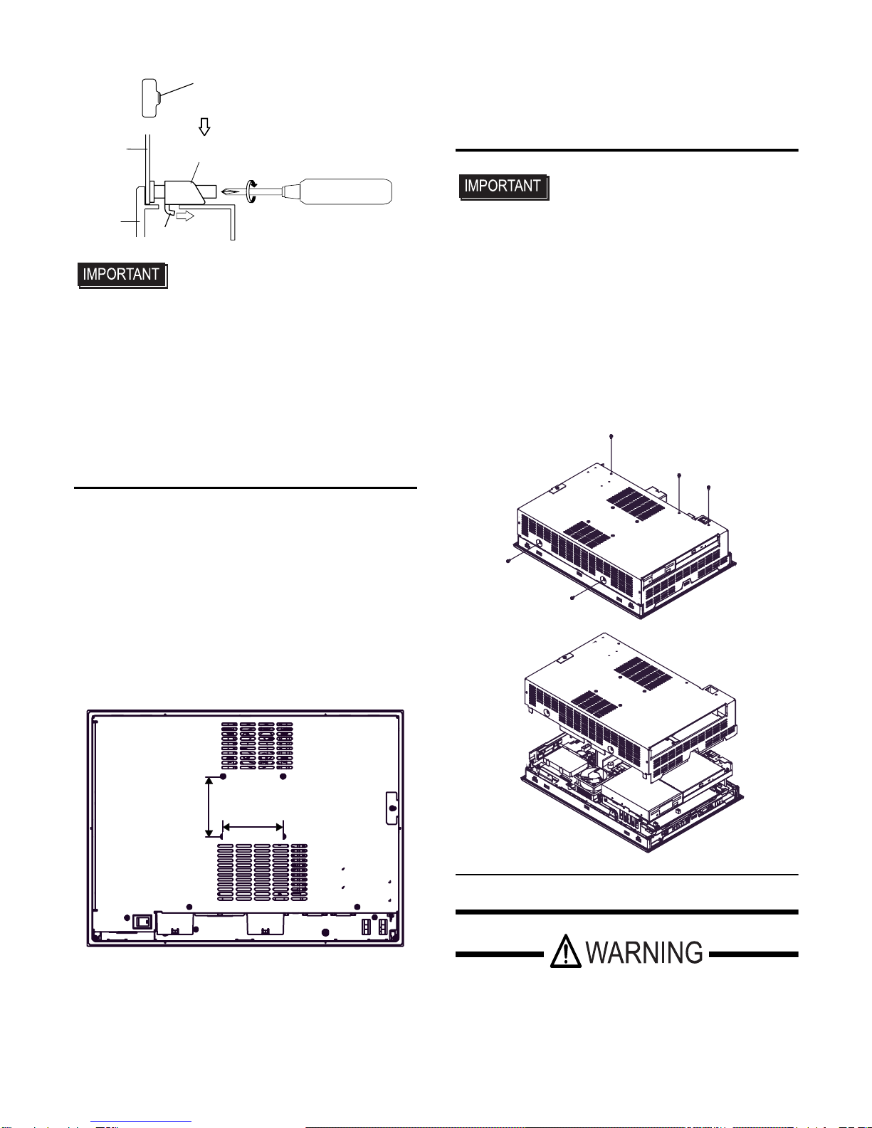
2. PS-A Installation
(1) Create a Panel Cut following the dimen-
sions in the table below.
(2) Confirm that the installation gasket is
attached to the PS-A unit and then place
the PS-A unit into the Panel from the front.
• It is strongly recommended that you
use the installation gasket, since it
absorbs vibration in addition to repel-
ling water.
For the procedure for replacing the
installation gasket, refer to “PS-3710A/
PS-3711A Series Hardware Manual”.
(3) Insert each fastener’s hook into the slot
and tighten it with a screwdriver. Insert
the installation fasteners securely into
the insertion slot recess. There are eight
insertion slots.
50
[1.97]
50
[1.97]
50
[1.97]
50
[1.97]
[1.97]
50
[1.97]
50
[1.97]
50
Unit:mm[in.]
Panel Face Inside Cabinet
50mm
30mm 30mm
PS-A X Y Panel
thickness
PS-
3710A
383.5
[
15.10
]
282.5
[
11.12
]
1.6[0.06]
to
10.0[0.39]
X
PS-A
Y
Unit: mm [in.] r ≤ 3[0.12] Panel
thickness
+1
-0
+0.04
-0
+1
-0
+0.04
-0
Insertion
Slots
11
• Tightening the screws with too much
force can damage the PS-A unit.
• The necessary torque is 0.5N•m.
• Be sure to insert installation fasteners
in the recessed portion of an installa-
tion fasteners hole. If the fasteners are
not correctly attached, the PS-A unit
may shift or fall out of the panel.
3. Attach the PS-A unit to an Arm
To attach the PS-A unit to an Arm or to the
wall, insert the attachment screws for a
commercial-type arm or wall mount adaptor
into the holes in the PS-A’s rear face.
(Holes specifications: VESA 75mm)
For detailed attachment instructions, please
refer to that product's installation guide. The
VESA Arm Attachment Hole dimensions are
signifies as follows;
Arm Attachment Screw Holes (VESA
75mm).
Attach the four (4) M4 attachment screws.
(Screw length: 6mm (0.24 in.) or less.) The
torque required for these screws is 0.7 to 0.8
N•m.
4. Removal/Attachment the Rear
Cover
• Use a screwdriver to loosen or tighten
the screws. Be sure not to tighten
screws too tightly, since it may damage
the unit.
• Be careful when removing or inserting
any screws that they do not fall inside
the PS-A.
Unscrew the five (5) attachment screws used
to hold the Rear Cover in place, and remove
the Rear Cover. The torque of the rear cover
required for these screws is 0.5 to 0.6 N•m.
Wiring
• To avoid an electric shock, prior to con-
necting the PS-A unit’s power cord ter-
minals to the power terminal block,
confirm that the PS-A unit’s power sup-
Insertion Slot Recess
Hook the fastener
on the Recess,
Panel Installation Fastener
PS-A Hook and secure the fastener
on the panel with a screw.
75[2.95]
75[2.95]
Rear Face
(unit:mm[in.])
12
ply is completely turned OFF, via a
breaker, or similar unit.
• Supplying a power voltage other than
that specified can damage the PS-A
and the power supply.
• Since the PS3710A-T42-24V has no
power ON/OFF switch, be sure to
attach a breaker-type switch to its
power cord.
• When the FG terminal is connected, be
sure the wire is grounded.
• When the FG terminal is connected, be
sure the wire is grounded. Not
grounding the PS-A unit will result in
excessive noise. Use your country's
applicable standard for grounding.
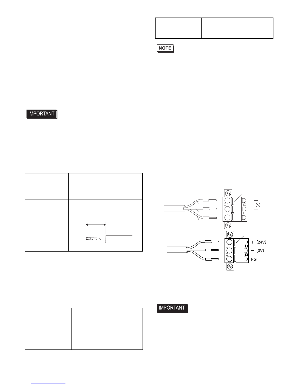
Power Cord Specifications
Use copper conductors only.
Wiring
When connecting the power cord, use the fol-
lowing items when performing wiring.
(Items are made by Phoenix Contact.)
• Accompanying AC type power supply
plug is CA7-ACCNL-01 from Pro-face or
FKC2.5/3-STF-5.08 is manufactured by
Phoenix Contact.
• Accompanying DC type power supply
plug is CA7-DCCNL-01 from Pro-face or
GFKC2.5/3-STF-7.62 is manufactured by
Phoenix Contact.
Connecting the Power Cord
(1) Confirm that the power is not supplied to
the PS-A unit.
(2) Push the Opening button with a small and
flat screw driver to open the desired pin
hole.
(3) Insert each pin terminal into its each hole.
Release the Opening button to clamp the
pin in place.
(4) After inserting all three pins, insert the
Power Plug into the Power Connector at
PS-A. Fix the plug with two (2) slot
screws.
• Confirm that all wires are connected
correctly.
• The torque required to tighten these
screws is 0.5 to 0.6N•m.
• To prevent the possibility of a terminal
short, use a pin terminal that has an
insulating sleeve.
Power Cord
Diameter 0.75 to 2.5mm2
(18 to 12 AWG)
Conductor Type Simple or Stranded Wire*1
*1 If the Conductor’s end (individual) wires are
not twisted correctly, the end wires may either
short against each other, or against an electrode.
Conductor
Length
Recommended
Driver SZS 0.6x3.5 (1205053)
Recommended
Pin Terminals
AI 0.75-10GY (3201288)
AI 1-10RD (3200182)
AI 1.5-10BK (3200195)
AI 2.5-12BU (3200962)
10mm
Recommended
PinTerminalCrimp
Tool CRIMPFOX ZA3 (1201882)
L
N
FG
Opening Button
Black
White
Green/Yellow
AC power supply cord
DC power supply cord Opening Button
13
1. Power Supply Cautions
• Input and Output signal lines must be sepa-
rated from the power control cables for
operational circuits.
• To improve the noise resistance, be sure to
twist the ends of the power cord wires
before connecting them to the Power Plug.
• The PS-A unit’s power supply cord should
not be bundled with or kept close to main
circuit lines (high voltage, high current), or
input/output signal lines.
• To reduce noise, make the power cord as
short as possible.
• If the supplied voltage exceeds the PS-A
unit’s range, connect a voltage transformer.
• Between the line and the ground, be sure to
use a low noise power supply. If there is an
excess amount of noise, connect a noise
reducing transformer.
• The temperature rating of field installed
conductors: 75°C only.
• Use voltage and noise reducing trans-
formers with capacities exceeding
Power Consumption value.
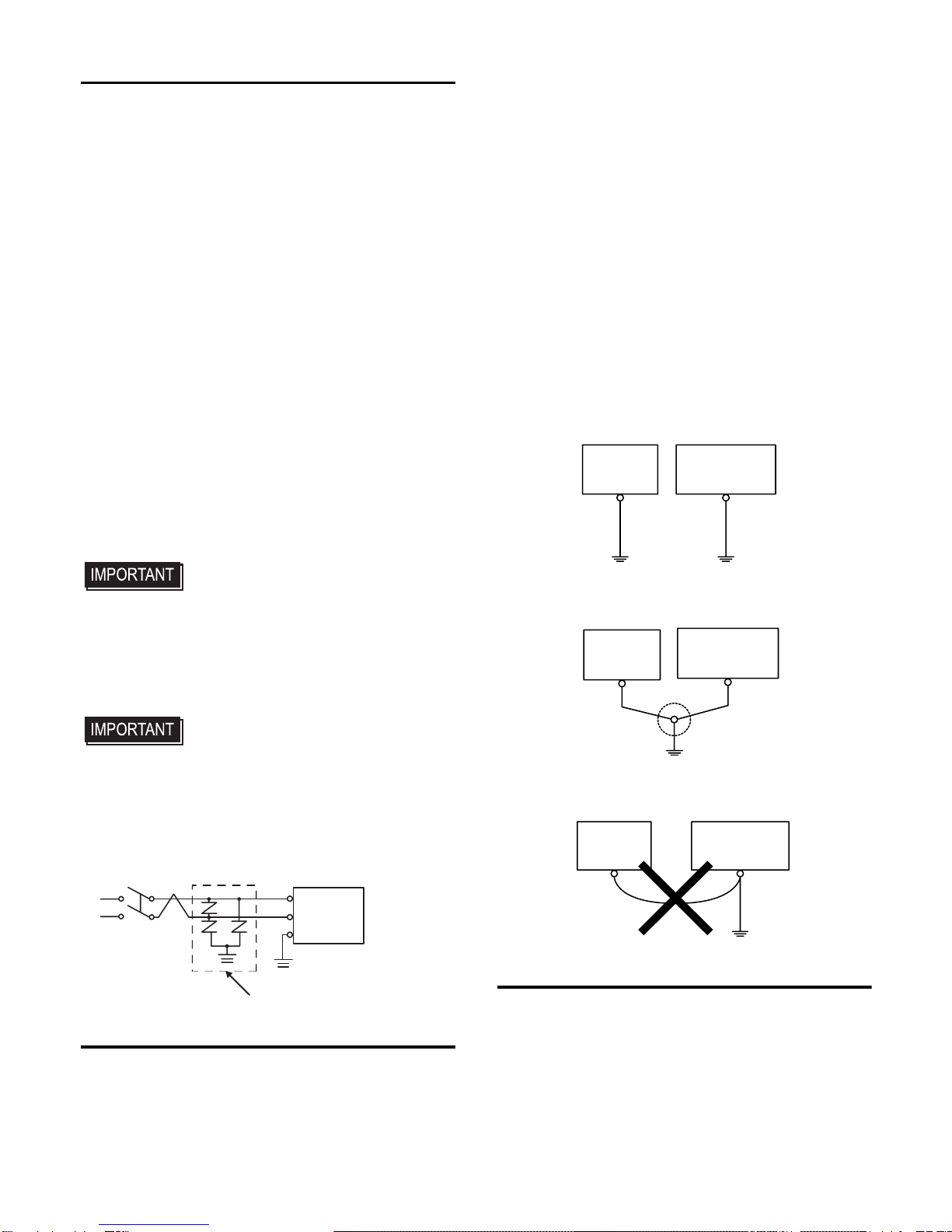
• Connect a surge absorber to handle power
surges.
• Be sure to ground the surge absorber
(E1) separately from the PS-A unit
(E2). Select a surge absorber that has
a maximum circuit voltage greater than
that of the peak voltage of the power
supply.
2. Grounding Cautions
• Be sure to create an exclusive ground for
the Power Cord’s FG terminal. Use a
grounding resistance of 100Ω, a wire of
2mm2or thicker, or your country’s applica-
ble standard.
• The SG (signal ground) and FG (frame
ground) terminals are connected internally
in the PS-A unit.
When connecting the SG line to another
device, be sure that the design of the sys-
tem/connection does not produce a short-
ing loop.
• The grounding wire should have a cross
sectional area greater than 2mm2. Create
the connection point as close to the PS-A
unit as possible, and make the wire as
short, as possible. When using a long
grounding wire, replace the thin wire with
a thicker wire, and place it in a duct.
3. Input/Output Signal Line Cautions
• All PS-A Input and Output signal lines
must be separated from all operating cir-
cuit (power) cables.
• If this is not possible, use a shielded cable
and ground the shield.
Lightning Surge Absorber
E1 E2
FG
PS-A
Other
Equipment
Exclusive Grounding
(BEST)
PS-A unit
Other
Equipment
Common Grounding (OK)
PS-A unit
Other
Equipment
Common Grounding
(Not OK)
PS-A unit

14
• To improve noise immunity, it is recom-
mended to attach a ferrite core to the
power cord.
Attaching the Power Switch cover
For the AC type to conform to ANSI/ISA
standards, the Power Switch cover needs to
be attached to the main unit.
To prevent the USB cable
from coming off
Attaching the USB Cable Clamp
(1) Place the PS-A unit face-down on a flat
surface as shown below. Your PS-A unit
has four USB connectors.
• When using two or more USB ports, be
sure to first connect one USB cable to the
lower USB connector, and then connect the
second USB cable to the upper USB
connector.
• When using only one of the USB ports, be
sure to use the lower USB connector. This
allows you to securely clamp the USB
cable in the cable clamp.
(2) As shown, insert the USB Cable Clamp’s
band through the Bridge. Pass the USB
cables through the Cable Clamp’s band
and securely tighten the clamp band
around the cables.
• Be sure the clamp is securely holding the
USB cable’s plug and collar.
• Be sure the clamp is positioned as shown
below, with the clamp pointing upwards -
not to the side. This is to keep the clamp
from interfering with nearby connectors
and their cables.
Removing the USB Cable Clamp
(1) To remove the clamp from the USB
cables, push down on the clamp strap’s
clip to release it while pulling up on the
clamp.
Installation prerequisites for
standards
For the detailed certification's information,
refer to the Pro-face Home page.
<Cautions>
Be aware of the following items when building the
PS-A into an end-use product:
The torque is 0.5 to
0.6N•m.
Upper USB Interface
Lower USB Interface
Band
Clamp
Cable collar
USB Cable
Bridge
Clamp
Clip
15
• The PS-A unit’s rear face is not approved as an
enclosure. When building the PS-A unit into an
end-use product, be sure to use an enclosure that
satisfies standards as the end-use product’s overall
enclosure.
• The PS-A unit must be used indoors only.
• Install and operate the PS-A with its front panel
facing outwards.
• If the PS-A is mounted so as to cool itself naturally,
be sure to install it in a vertical panel. Also, it’s rec-
ommended that the PS-A should be mounted at
least 50mm [1.97in.] away from any other adjacent
structures or machine parts. The temperature must
be checked on the final product in which the PS-A
is installed.
• For use on a flat surface of a Type 4X (Indoor Use
Only) and/or Type 12 Enclosure.
• Type 4X (Indoor Use Only) and/or 12 Enclosure,
when the hatch for Front USB Port is secured with a
screw.
Type 1 Enclosure, when the hatch for Front USB
Port is open.
<Hazardous Locations -
Compliance and Handling Cautions>
• Suitable for use in Class I, Division 2, Groups A,
B, C, and D Hazardous Locations only.
• WARNING: Explosion hazard - substitution of
components may impair suitability for Class I,
Division 2.
• WARNING: Explosion hazard - do not disconnect
equipment while the circuit is live or unless the
area is known to be free of ignitable concentra-
tions.
• WARNING: Explosion hazard - when using the
PS-A with the AC type power supply, be sure to
attach the Power Switch Cover.
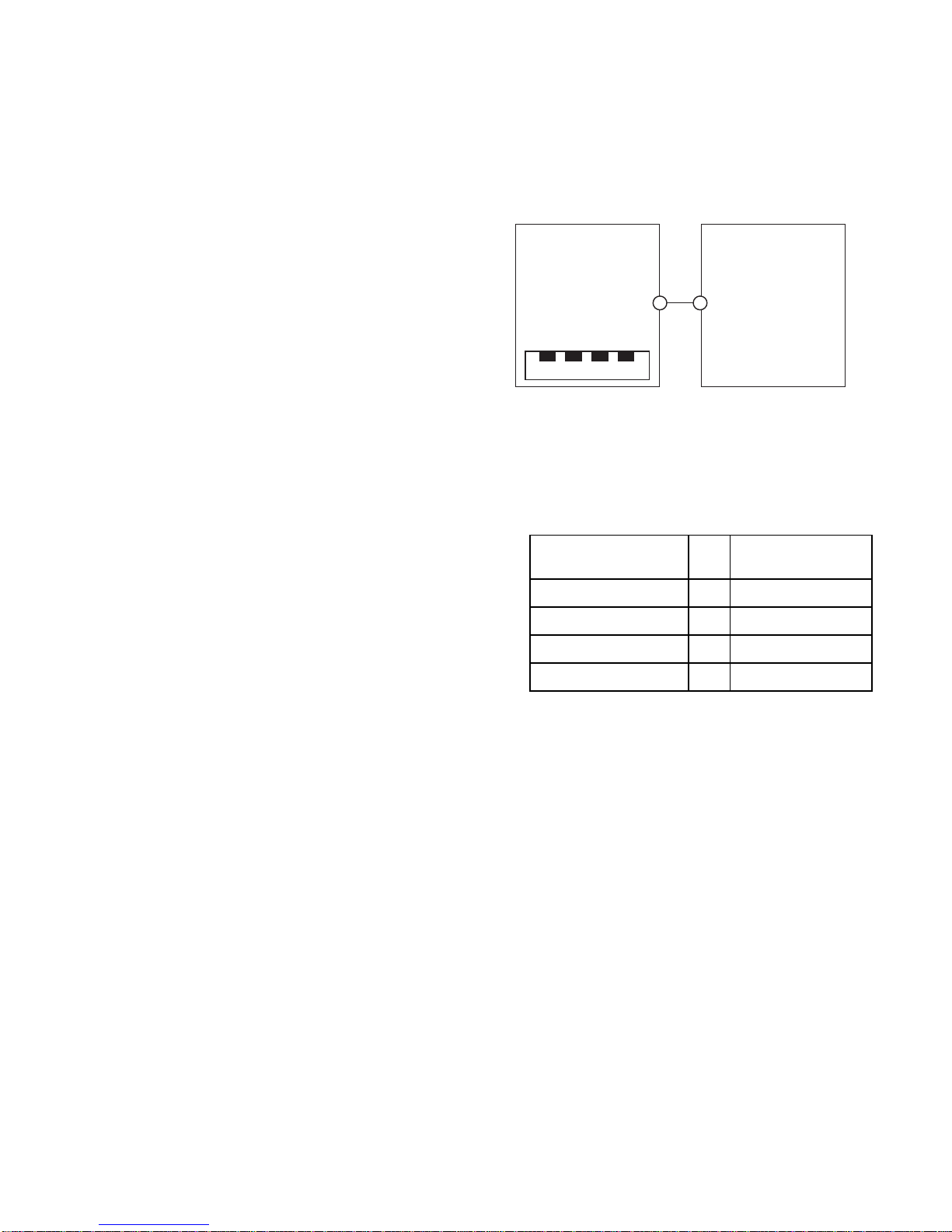
<Control Drawing of USB I/F on PS-
A's Front Module>
The information below concerns the use of the USB
I/F located on the PS-A unit's front modules used in
Class I, Division 2 Groups A, B, C, and D hazardous
locations (from Doc No. 35016429).
PS-A's Front Module
Notes:
1. Nonincendive Circuit Parameters:
Front USB I/F:
Voc = 5.0 V, Isc = 1.25 A, Ca = 10 µF,
La = 16 µH
2. Selected Associated Nonincendive Field Wiring
Apparatus shall satisfy the following:
3. If the electrical parameters of the cable are
unknown, the following values may be used:
Capacitance = 60pF/ft, Inductive = 0.20 µH/ft
4. Nonincendive Field Wiring must be installed in
accordance with article 501.10(B) of the
National Electrical Code ANSI/NFPA 70.
5. Nonincendive Field Wiring Apparatus shall not
contain or be connected to another source of
power.
Nonincendive Field
Wiring Apparatus -Front module
of PS-A unit
Voc ≤Vmax
Isc ≤Imax
Ca ≥Ci+C cable
La ≥Li+L cable
USB Pin Description
(See note 1 for detail)
Shield. Gnd
1.Vcc
2.D
-
3.D+
4.GND
1234
Nonincendive Field
Wiring Apparatus
16
CE Marking
•PS3710A-T42 unit is a CE marked product that
conforms to EMC directives and Low Voltage
Directives.
•PS3710A-T42-24V is a CE marked product
that conforms to EMC directives.
For the detailed information, please be
downloaded and refer the Declaration of
Conformity from Pro-face Home Page.
Digital Electronics Corporation
8-2-52 Nanko-higashi
Suminoe-ku, Osaka 559-0031
JAPAN
TEL: +81-(0)6-6613-3116
FAX: +81-(0)6-6613-5888
http://www.pro-face.com/
© Copyright 2009 Digital Electronics Corporation. All
rights reserved.
PFX106519K .PS3710A-MT23E-BTH
2012.3 JM/D
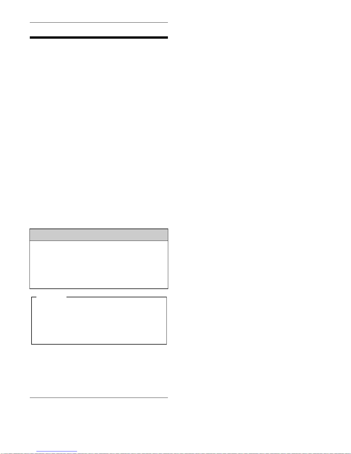
Inquiry
Do you have any questions about
difficulties with this product?
Please access our site anytime that
you need help with a solution.
http://www.pro-face.com/otasuke/
Please be aware that Digital Electronics
Corporation shall not be held liable by the
user for any damages, losses, or third
party claims arising from the uses of this
product.
Note
This manual suits for next models
1
Table of contents
Other Pro-face Industrial Monitor manuals


Popular Industrial Monitor manuals by other brands

Hope Industrial Systems
Hope Industrial Systems HIS-UM17 E Series user manual

Sahara
Sahara 1090010 user manual

Siemens
Siemens SIMATIC Industrial Flat Panel IFP1500 quick start guide

Hitachi
Hitachi CML181SXW Service manual

Bosch
Bosch Rexroth ctrlX HMI DE0015 operating instructions

Austin Hughes
Austin Hughes CyberView RP-920 user manual


