Pro-tec PRS 500 X User manual
PROTEC GmbH & Co. KG
In den Dorfwiesen 14, 71720 Oberstenfeld, Germany
Version: 5.0
Issued: 2020-11-12
Subject to alterations
PRS 500 X
Basic diagnostic X-ray syst m
Mod l/ID: 7066-9-8050
Instructions for us
Ident. Nr. 5066-0-8002
PRS 500 X
in analogue base configuration

NOTE
All sheets of this document contain proprietary and confidential information of
PROTEC GmbH & Co. KG and is intended for exclusive use by current PROTEC GmbH
& Co. KG customers. Copying, disclosure to other or other use is prohibited without
the express written authorization of PROTEC´s law department. Report any
violations of this requirement to PROTEC GmbH & Co. KG.
© 201 PROTEC GmbH & Co. KG, Oberstenfeld
These accompanying documents were created and distributed by the documentation department.
Comments and questions about the documentation, please contact:
PROTEC GmbH & Co. KG
In den Dorfwiesen 14 | 71720 Oberstenfeld
Deutschland
Phon : (+ 49) 7062 – 92 55 0
Fax: (+ 49) 7062 – 92 55 60
E-Mail: prot c@prot c-m d.com
Int rn t: www.prot c-m d.com

PRS 500 X
Instructions for use
5066
-
0
-
8
002
PROTEC GmbH & Co. KG, In den Dorfwiesen 14, 71720 Oberstenfeld, Germany
3
von
40
Tabl of cont nts
Pag
Tabl of cont nts ........................................................................................................................... 3
Docum nt Eff ctivity .................................................................................................................... 5
G n ral Not s ................................................................................................................................ 6
M chanical – El ctric Warning .................................................................................................... 6
Radiation Warning ........................................................................................................................ 6
To th Us r ..................................................................................................................................... 7
1
Product d scription ............................................................................................................ 8
1.1 Introduction ......................................................................................................................................................................................... 8
1.2 Description............................................................................................................................................................................................ 8
1.2.1 Equipment components ................................................................................................................................................. 8
1.2.2 Installation ................................................................................................................................................................................
1.2.2.1 Floor capacity ...................................................................................................................................................................
1.3 Product specific characteristics ................................................................................................................................................
1.3.1 X-ray system tube support, floor stand ..................................................................................................................
1.3.2 X-ray system image receptor stand ..........................................................................................................................
1.4 Intended use ........................................................................................................................................................................................
1.5 Indication and Contraindication .......................................................................................................................................... 10
1.5.1 Indications ............................................................................................................................................................................. 10
1.5.2 Contra indications ............................................................................................................................................................. 10
1.6 Intended user group .................................................................................................................................................................... 10
1.7 Conformity ......................................................................................................................................................................................... 11
2
Saf ty Instructions ............................................................................................................ 12
2.1 General safety notice ................................................................................................................................................................... 14
2.1.1 Requirements for operation ....................................................................................................................................... 14
2.1.2 Operating of the radiographic system ................................................................................................................. 14
2.1.3 Operating type .................................................................................................................................................................... 14
2.1.4 Operating personnel ....................................................................................................................................................... 14
2.1.5 Pinching and Collision Hazards ................................................................................................................................ 15
2.1.6 Explosion protection ....................................................................................................................................................... 15
2.1.7 Radiation protection ....................................................................................................................................................... 15
2.1.8 Ventilation .............................................................................................................................................................................. 15
2.1. Interaction with external devices ............................................................................................................................ 15
2.1.10 Electromagnetic Environment and the influence of devices ................................................................ 16
3
Control l m nts and d vic displays ........................................................................... 17
3.1 Control elements and device displays PROGNOST SH ........................................................................................... 17
3.1.1 Operating unit PROGNOST SH, Standard .............................. F hl r! T xtmark nicht d fini rt.
3.1.2 Operating unit PROGNOST SH, TOUCH .................................. F hl r! T xtmark nicht d fini rt.
3.2 Control elements and device displays collimator ..................................................................................................... 20
3.3 Control elements and device displays of X-ray tube ............................................................................................... 20
3.4 Control elements and device displays of X-ray generator ................................................................................... 20
3.5 Control elements of Bucky, Grid entity ............................................................................................................................. 20
3.6 Control elements and device displays of X-ray system image receptor stand PROVERT ................. 21
3.6.1 Vertical carriage .................................................................................................................................................................. 21
3.7 Control elements and device displays of RAPIXX system ..................................................................................... 21
3.8 Control elements and device displays of CONAXX 2 .............................................................................................. 21
4
Handling / Op ration ........................................................................................................ 22
4.1 Operation with the radiographic system ........................................................................................................................ 22
4.1.1 Operation at the X-ray system table ...................................................................................................................... 22
4.1.1.1 Position of patients on the tabletop* ............................................................................................................. 22
4.1.1.2 Setting the X-ray unit on the mid moving Bucky, Grid entity ......................................................... 22
4.1.1.3 Inserting a cassette into the cassette tray .................................................................................................... 22
4.1.1.4 Adjusting the focus-film distance (FFD) ........................................................................................................ 22

PRS 500 X
Instructions for use
5066
-
0
-
8
002
PROTEC GmbH & Co. KG, In den Dorfwiesen 14, 71720 Oberstenfeld, Germany
4
von
40
4.1.1.5 Adjusting the light resp. X-ray field .................................................................................................................. 22
4.1.1.6 Exposure preparation / exposure release .................................................................................................... 22
4.1.1.7 Overtable exposures ................................................................................................................................................. 22
4.1.2 Operation at X-ray system image receptor stand PROVERT ................................................................... 24
4.1.2.1 Adjustment of the X-ray unit to the mid of a cassette or Bucky/Grid entity of a X-ray
system image receptor stand (vertical center beam) ................................................................................................. 24
4.1.2.2 Adjustment of the source to image-receptor distance (SID) ........................................................... 24
4.1.2.3 Adjustment of the light-/ radiation field....................................................................................................... 24
4.1.2.4 Exposure preparation/ release ............................................................................................................................ 24
4.2 Operation collimator ................................................................................................................................................................... 24
4.3 Operation X-ray tube ................................................................................................................................................................... 24
4.4 Operation X-ray generator ....................................................................................................................................................... 25
4.5 Operation Bucky, Grid entity ................................................................................................................................................... 25
4.6 Operation X-ray system image receptor stand PROVERT ..................................................................................... 25
4.7 Operation RAPIXX system......................................................................................................................................................... 25
4.8 Operation Software ...................................................................................................................................................................... 25
4. Function of the PRS 500 X ........................................................................................................................................................ 25
4. .1 Switching On/Off the PRS 500 X .............................................................................................................................. 25
4. .2 Dosimetric Calibration (only for PROVARIO HF) ............................................................................................. 25
4.10 Exposure automatic ..................................................................................................................................................................... 26
5
Saf ty and Maint nanc ................................................................................................... 27
5.1 Introduction ...................................................................................................................................................................................... 27
5.2 Cleaning and disinfection ......................................................................................................................................................... 27
5.2.1 Cleaning .................................................................................................................................................................................. 27
5.2.2 Disinfection ........................................................................................................................................................................... 27
5.3 Check-up and maintenance ................................................................................................................................................... 28
5.3.1 Daily Controls (prior to or during the unit operation) ................................................................................ 28
5.3.2 Regular controls ................................................................................................................................................................. 28
5.3.3 Only original spare parts are to be used in situations requiring component replacement
Maintenance ................................................................................................................................................................................................ 28
5.3.4 Warranty .................................................................................................................................................................................. 28
5.3.5 Product life time ................................................................................................................................................................. 28
5.3.6 Further Information ......................................................................................................................................................... 28
5.3.7 Applied Parts and parts which get handled like an application part ................................................ 2
5.3.8 Disposal ................................................................................................................................................................................... 2
6
El ctrical data ..................................................................................................................... 30
6.1 Electromagnetic Compatibility (EMC) after EN 60601-1-2 ................................................................................... 31
6.1.1 Guidelines and Manufacturers declaration – electromagnetic interference (non-life
supporting device) ................................................................................................................................................................................... 31
7
T chnical Data .................................................................................................................... 32
7.1 Dimensions ........................................................................................................................................................................................ 32
7.2 X-ray system tube support, floor stand ............................................................................................................................ 34
7.3 X-ray system image receptor stand .................................................................................................................................... 34
7.4 Attenuation Equivalent .............................................................................................................................................................. 34
7.4.1 Protection Art and Protection Class ....................................................................................................................... 34
7.5 Automatic cutoff dose ................................................................................................................................................................ 34
7.5.1 Analogue System .............................................................................................................................................................. 34
7.5.2 Digital System ...................................................................................................................................................................... 34
7.6 Environmental ................................................................................................................................................................................. 35
7.6.1 Environmental conditions during operation ................................................................................................... 35
7.6.2 Environmental Conditions for Shipping and Storage ................................................................................ 35
8
D scription of symbols, lab ls and abbr viations ....................................................... 36
8.1 Symbols ............................................................................................................................................................................................... 36
8.2 Identification label......................................................................................................................................................................... 37
8.3 Labels .................................................................................................................................................................................................... 38
8.4 Position symbols and labels .................................................................................................................................................... 3
8.5 Abbreviations ................................................................................................................................................................................... 40

PRS 500 X
Instructions for use
5066
-
0
-
8
002
PROTEC GmbH & Co. KG, In den Dorfwiesen 14, 71720 Oberstenfeld, Germany
5
von
40
NOTE
The information contained in this document conforms to the configuration of the
equipment as of the date of manufacture. Revisions to the equipment subsequent
to the date of manufacture will be addressed in service updates distributed to the
PROTEC Technical Service Organization.
Docum nt Eff ctivity
R vision No. Dat List of ff ctiv pag s Comm nts
1.0 201 -05-14 all
New created, replaces
document 5061-0-
0002_V4
2.0 201 -07-31 Cap. 1.2, 6.1.1, 7.1, 8.1, 8.2,
8.4
GMDN terms updated
Changed optional
accessories and images
dimension
EMC tables removed
Symbols added
Identification label
updated
3.0 2020-06-1 Cap. 1.2.2.1, 1.3.1, 3.1, 7.2 Telescopic arm added
4.0 2020-08-11 Front page, Cap. 5.3.3 Maintenance updated
5.0 2020-11-12 Cap. 1.2.1; Cap.6; Cap. 3.1.1;
Cap. 3.1.2; Cap. 4.1.1.8
New generators,
Rotatable X-ray column
added

PRS 500 X
Instructions for use
5066
-
0
-
8
002
PROTEC GmbH & Co. KG, In den Dorfwiesen 14, 71720 Oberstenfeld, Germany
6
von
40
G n ral Not s
WARNING!
No chang s of th ME d vic !
M chanical – El ctric Warning
WARNING!
All of th movabl ass mbli s and parts of this quipm nt should b op rat d
with car and routin ly insp ct d in accordanc with th manufactur r's
r comm ndations contain d in th quipm nt Accompanying Docum nts.
Maint nanc and s rvic is only to b p rform d by Custom rs authoriz d by
PROTEC GmbH & Co. KG.
Liv l ctrical t rminals ar d adly.
Do not r mov fl xibl high-t nsion cabl s from X-ray tub housing or high-
t nsion g n rator and/or acc ss cov rs from X-ray g n rator.
For all compon nts of th quipm nt prot ctiv arthing m ans must b
provid d in complianc with th national r gulations.
Failur to comply with th for going may r sult in s rious or fatal bodily
injuri s to th op rator or thos in th ar a.
Radiation Warning
WARING!
Th compon nt of th quipm nt d scrib d within this Docum nt is part of a
syst m for th int nd d g n ration of X-rays for m dical diagnosis.
X-rays g n rat a pot ntial risk for both pati nts and op rators.
For this r ason, th application of X-rays for a giv n m dical purpos must
aim at th minimization of radiation xposition to any p rsons. Thos p rsons
r sponsibl for th application must hav th sp cific knowl dg according
to l gal r quir m nts and r gulations and must stablish saf xposur
proc dur s for th s kinds of syst ms. Thos p rsons, r sponsibl for th
planning and installation of this quipm nt, must obs rv th national
r gulations.
Th syst m caus s diff r nt ionising radiation. Th purpos is to cr at
charact ristic X-ray radiation. Th int nsity d p nds on th adjust d valu s of
voltag , curr nt and tim . Th radiation com s orthogonal out of th X-ray
tub and is limit d by th collimator.

PRS 500 X
Instructions for use
5066
-
0
-
8
002
PROTEC GmbH & Co. KG, In den Dorfwiesen 14, 71720 Oberstenfeld, Germany
7
von
40
To th Us r
NOTE
The user of this Document is directed to read and carefully review the instructions,
warnings and cautions contained herein prior to beginning operation, installation or
service activities.
While you may have previously operated equipment similar to that described in this
Document, changes in design, manufacture or procedure may have occurred which
significantly affect the present operation.
Although the product was subject to a risk analysis and the design corresponds to
the current state of the art, residual risk will remain in clinical use. These are
displayed in the following user manual by application limitations, contraindications,
warnings and precautions.
The installation and service of equipment described herein is to be performed by
authorized, qualified PROTEC GmbH & Co. KG Customers.
Assemblers and other Customers not employed by nor directly affiliated with
PROTEC GmbH & Co. KG technical services are directed to contact the local
PROTEC GmbH & Co. KG office before attempting installation or service
procedures.
For Installations and service procedures it is necessary to read the „technical
description“of the product and to observe any containing point in it.
NOTE
The usage of the product in combination with accessories which aren’t authorized
by PROTEC is forbidden.

PRS 500 X
Instructions for use
5066
-
0
-
8
002
PROTEC GmbH & Co. KG, In den Dorfwiesen 14, 71720 Oberstenfeld, Germany
8
von
40
1
Product d scription
1.1 Introduction
This user manual describes the special features and operational aspects of the PRS 500 X, knowledge of
which are required for efficient and effective use of the radiographic system.
Prior to working with the PRS 500 X, it is required that the user reads the Safety Notes as well as the
chapter regarding operation.
1.2 D scription
1.2.1 Equipm nt compon nts
The PRS 500 X consists of the following components:
•Floor railed X-ray system tube support with control arm,
•Bucky or Grid entity,
•X-ray system image receptor stand,
•X-ray Generator, PROVARIO HF-, VENUS-, CMP- or RFX series
•X-ray tube assembly with housing,
•Collimator
Optional compon nts
•Anti-scatter Grid
•3-field measuring chamber,
•Dose area product meter system and
•Different direct X-ray-systems (RAPIXX-Serial)
(consisting of DR-detector, Interface Box, and Software)
•Software CONAXX 2
Optional Acc ssori s
The PRS 500 X can be equipment or customized with the following accessories:
•Patient extending handle
•Compression band
•Strain relief cable hose X-ray system image receptor stand
•Mobile patient X-ray system table for digital or conventional exposures from the PROTEC
PROGNOST series
−PROGNOST XS
−PROGNOST XP
−PROGNOST XPE
−PROGNOST XPE-Akku
−Lateral Detector holder
Only with rotatable X-Ray column PROGNOST SH and X-ray system table PROGNOST.
Acc ssori s which can influ nc th EMC-Condition
•Network cable (note the max. length in the documents)
•RAPIXX Data-Cable (note the max. length in the documents)
•WLAN-Router (only use devices that has an authorization by PROTEC)
•…

PRS 500 X
Instructions for use
5066
-
0
-
8
002
PROTEC GmbH & Co. KG, In den Dorfwiesen 14, 71720 Oberstenfeld, Germany
von
40
1.2.2 Installation
See separate “Installation manual” PRS 500 X.
Contact information of persons which are qualified to make installations are requestable at:
PROTEC GmbH & Co. KG
In den Dorfwiesen 14 | 71720 Oberstenfeld
Telephone: +4 (0) 7062 – 2 55 0
Fax: +4 (0) 7062 – 2 55 60
E-Mail: protec@protec-med.com
Internet: www.protec-med.com
1.2.2.1 Floor capacity
NOTE
T
he
radiographic
system is primarily made of metal pieces. This has a main role in
the weight of the device.
The radiographic system PRS 500 X has a w ight of 642kg (incl. Generator),
option: telescopic arm 30kg (additionally).
Every technician is obliged to check the ground load. Also double bottoms and
hollow floors have to be taken into account.
1.3 Product sp cific charact ristics
1.3.1 X-ray syst m tub support, floor stand
•Ceiling-free column stand intended for use within rooms with a ceiling height of at least 2.3
meters
•Wide range of application
•Small wall distance allows good space utilization
•Control elements within the command arm well placed and easy to activate
•Reproducible positioning of the X-ray tube assembly (positions resulting from rotation around
the axis of the carrying arm) through angle indicator
•Vertical range of travel of the focus height from 2 .4 cm up to 188.2 cm during horizontal
beam projection
•Electromagnetic brakes for the longitudinal movement of the column stand, the vertical
movements of the carrying arm, the rotational movements of the X-ray tube assembly around
the axis of the carrying arm +/-180° with integrated latching every 0° as well as transversal
movement of the carrying arm +230mm (optional).
•Integrated safety connector for automatically centering the X-ray tube assembly and the Bucky
in the longitudinal direction
1.3.2 X-ray syst m imag r c ptor stand
•Space saving with minimal footprint
•Wall – floor mounting of floor mounting
•cassette loading from the right or left side (specified at installation)
•Useable for variable cassette/detector sizes. Formats from 13 cm x 18 cm (5” x 7”) to 43 cm x 43
cm (17” x 17”), depending on analog or digital use
1.4 Int nd d us
The general-purpose diagnostic radiographic systems of the PRS 500-series are intended for various
routine applications in planar X-ray imaging in human medicine.
They are stationary systems that can be used both for analogue and digital imaging.

PRS 500 X
Instructions for use
5066
-
0
-
8
002
PROTEC GmbH & Co. KG, In den Dorfwiesen 14, 71720 Oberstenfeld, Germany
10
von
40
NOTE
At the accept
ance test a 25mm Aluminium / .
5% purity can be used as a
phantom for a patient equivalent.
The acceptance test has to be made in accordance to the local laws and directives.
Only Special trained People are allowed to do this.
1.5 Indication and Contraindication
1.5.1 Indications
Justification of m dical xposur s
According to §83 of the German radiation protection law (StrlSchG), an X-ray examination is only
justified if the patients benefit from x-ray diagnostics outweighs the radiation risk. The examination
method, means the conventional X-ray with the PRS 500 system, must be suitable to answer the
diagnostic question and no other more suitable alternative method is available.
Accordingly, it is also described by the International Atomic Energy Agency (IAEA) in the document
Radiation Protection and Safety of Radiation Sources: International Basic Safety Standards (Requirement 37:
Justification of medical exposures). It also refers to the need to consider national or international
guidelines for the justification of a medical exposure.
A complete list of indications is unrealisable for conventional radiography, because the spectrum of
conventional X-rays is very diverse and can vary in the course of medical-technical progress.
Some examples of indications for an X-ray examination may be:
•For the diagnosis of a bone fracture or bony injuries of the skeletal system or pathological
changes of hard tissues.
•To control the bone setting.
•For the diagnosis of luxations and ligament ruptures of the locomotor system.
•For the diagnosis of degenerative, inflammatory, traumatic and tumorous diseases and
changes of the locomotor system.
•For diagnostic of malformations and malalignments of the skeletal system.
•For the diagnosis of thoracic and pulmonary symptoms (thorax exposures)
•For the diagnosis of sclerotherapy.
•For the diagnosis of inflammatory and expansive processes of the mucosa, cranial bones and
paranasal extension.
•For the diagnosis of the abdomen (e.g. acute abdomen, plain abdominal radiography,
urethrogram, cystogram).
1.5.2 Contra indications
There are no absolute contraindications for conventional X-rays.
But it is not allowed to make any exposures on humans when they are not medically indicated (see
Justification of medical exposures, chapter 1.5.1 Indication).
For pregnant women and children it is important to consider if the exposure is really necessary. It
should be avoided if possible.
1.6 Int nd d us r group
The radiographic system PRS 500 X is exclusively designated for use by professional who are trained, in
accordance with the corresponding national regulations, in the use of diagnostic X-Ry equipment and
its proper intended use in connection with other medical devices, objects and accessories.
Suitable users could include the following: Radiologist, radiology assistants, radiology technicians,
doctors and other medically trained personnel.

PRS 500 X
Instructions for use
5066
-
0
-
8
002
PROTEC GmbH & Co. KG, In den Dorfwiesen 14, 71720 Oberstenfeld, Germany
11
von
40
1.7 Conformity
This product is in conformity with the requirements of the European Community
Medical Device Directive 3/42/EEC from 06/14/1 3 including all current
revision standards.
The declaration of conformity is available directly from PROTEC:
PROTEC GmbH & Co. KG
In den Dorfwiesen 14 | 71720 Oberstenfeld
Telephone: +4 (0) 7062 – 2 55 0
Fax: +4 (0) 7062 – 2 55 60
E-Mail: protec@protec-med.com
Internet: www.protec-med.com

PRS 500 X
Instructions for use
5066
-
0
-
8
002
PROTEC GmbH & Co. KG, In den Dorfwiesen 14, 71720 Oberstenfeld, Germany
12
von
40
2
Saf ty Instructions
NOTE
Contains information that are relevant to the usage.
xxx
CAUTION!
Contains information that can cause damage to properties at
non conformity.
xxx
WARNING!
Contains information that can cause personal injuries at
nonconformity.
xxx
WARNING!
Warning of radioactive substances or ionisating rays. Contains
information that can cause personal injuries at non conformity.
xxx
Adjustments and calibrations that are described within the user manual must be made, with the aid of
The technical description for the system, by the PROTEC GmbH & Co. KG customer service
department or a PROTEC GmbH & Co. KG authorized service technician.
NOTE
Every delivered manual has to be read and the
safety notes
have to be observed
.
NOTE
After installation the
commissioning
have to be recorded with the PROTEC
acceptance protocol.
NOTE
For the digital system implementation the manuals of
CONAXX and RAPIXX have to
be read and the containing safety note have to be observed.
NOTE
The
commissioning
of the
radiographic
system can only be done if all
safety notes
and user securities have been met. The user securities can be: door contact, marked
area, dosimeter, safety clothes, …

PRS 500 X
Instructions for use
5066
-
0
-
8
002
PROTEC GmbH & Co. KG, In den Dorfwiesen 14, 71720 Oberstenfeld, Germany
13
von
40
CAUTION!
Th manual contains v ry saf ty r l vant information’s for th
commissioning of th syst m. Op rating th d vic is xclusiv ly for sp cial
train d staff. In this cont xt th r ar on v ry op rating l m nt r l vant
saf ty symbols. Furth r information ar on th d liv r d docum nt-CD. Thos
information count as additional information and hav to b obs rv d.
NOTE
Every operating element is marked on the operating console and on the swivel arm
or wall column, there are further descriptions for the symbols in the corresponding
manual. The lawfully requirements for building regulations for radiographic systems
have to be fulfilled. The radiographic system has to be checked according to the
local law and also accepted by the responsible office.
CAUTION!
If th wrong SID is in us for xposur s, p rsonal injuri s for th pati nt can
b th r sult. Th inv rs squar law tak s plac h r . Halving th distanc
will caus a 4 tim high r radiation dos .
WARNING!
It’s not allow d to mak any m dical not indicat d xposur s on p opl . At
pr gnancy or childr n th qu stion is if th xposur is r ally n c ssary. If
possibl it’s b tt r to abandon it.

PRS 500 X
Instructions for use
5066
-
0
-
8
002
PROTEC GmbH & Co. KG, In den Dorfwiesen 14, 71720 Oberstenfeld, Germany
14
von
40
2.1 G n ral saf ty notic
2.1.1 R quir m nts for op ration
WARNING!
Class I ME d vic
To r duc th risk of l ctric shock, this unit is d signat d xclusiv ly for
conn ction to a supply n twork with prot ctiv arth.
Th pow r for th compon nts of radiographic syst m PRS 500 X is
d signat d to b xclusiv ly suppli d through a dir ct conn ction to th
availabl X-ray g n rator. Th X-ray g n rator is r quir d to off r a minimum
of two conn ction ports with 230V 50/60Hz.
Th X-ray G n rator of th Syst m is dir ctly conn ct d to th pow r supply
(s t chnical d scription of th G n rator)
Th radiographic syst m PRS 500 X with stand is am ME Class I product.
This d vic contains no on/off switch. Th PRS 500 X is dir ctly conn ct d to
th X-ray g n rator and is switch d on/off through th switching on and off of
th g n rator its lf. In ord r to disconn ct th PRS 500 X from th pow r th
conn ct d X-ray g n rator must b shut off.
2.1.2 Op rating of th radiographic syst m
When having troubles with operating the radiographic system PRS 500 X, immediately call the Service
of PROTEC or an authorized service and stop the using of the system.
2.1.3 Op rating typ
The PRS 500 X is not designated for continuous use.
Duty Cycle: S3 15% - maximum continuous operation of 1,5 minutes.
2.1.4 Op rating p rsonn l
The radiographic system PRS 500 X with stand should only be operated by personnel who are trained
in accordance with the corresponding national regulations in the use and operation of diagnostic
radiographic systems.
NOTE
Only properly trained and authorized personnel are allowed to word with the
radiographic system PRS 500 X.
The user, as well as the service personnel, must pay attention to the warnings, notices and safety
instructions located on the device and in the user manual. Failure to comply with the information
provided can lead to injury.
NOTE
Operating personnel are required to acquaint themselves
with all warnings
(warning signs) located on the device PRS 500 X. They serve to ensure the safety of
the operator as well as others and set a basic for orderly operation.

PRS 500 X
Instructions for use
5066
-
0
-
8
002
PROTEC GmbH & Co. KG, In den Dorfwiesen 14, 71720 Oberstenfeld, Germany
15
von
40
2.1.5 Pinching and Collision Hazards
CAUTION!
Ensur that whil using any product that can b low r d, rais d or mov d in
diff r nt dir ctions, n ith r yours lf (op rator), th pati nt or any third party
finds th ms lv s in a hazardous position (ar a of mov m nt). R mov all
obj cts ( .g. chairs, pushcarts) from known collision ar as.
B awar that car l ss or improp r adjustm nt of th radiographic syst m
(mov m nt of column, d t ctor Bucky, X-ray syst m imag r c ptor stand
and tabl top) can l ad to damag of th X-ray compon nts, unusabl X-ray
imag s and injury to th pati nt. Failur to pay att ntion can l ad to damag
of th radiographic syst m as w ll as xt rnal obj cts.
2.1.6 Explosion prot ction
These radiographic system PRS 500 X is not designated for use within areas with explosive hazards.
2.1.7 Radiation prot ction
X-ray radiation can pose a hazard to patients and other people when the regulations regarding the
operation of radiographic systems are not followed.
For this reason, the basic principles of radiation protection are of the highest priority and must be
followed without exception:
•Distanc from th radiation sourc
The dosage is reduced as a factor of the square of the distance from a (dot shaped) radiation source.
Double the distance ¼ dose, triple the distance 1/ dose
•K p th xposur tim as short as possibl
The dosage is directly correlated with the exposure time. A half exposure time results in a radiation
dose half that of a full exposure. (This is especially pertinent with fluoroscopy, as X-ray images have
predetermined mAs).
•Utiliz shi lding and prot ctiv clothing
The protective value grows exponentially with the thickness of the shielding. Two half-value layer
thickness (HVL) weaken (homogeneous) radiation to ¼, 3 HVL to 1/8, und 10 HVL to less than 1/1000
of the original value.
•Do not r ach into th dir ct X-ray b am
The dosage in a un-weakened-Ray beam is around 100 times larger than that in the scattered
radiation.
•Us p rsonal dosag m t rs
In working with radiation (X-rays), the use of personal dosage monitors is suggested.
The X-ray images are principally triggered from behind a protective wall. For the creation of images
near the reproductive organs use the maximum available protection (e.g. testicular shielding or lead
covers)
People that must remain close to the patient are required to wear protective clothing (e.g. lead apron).
This counts for maintenance and installation work as well.
2.1.8 V ntilation
It is important to ensure that the air exchange of the X-ray generator within the system is not hindered.
The ambient air temperature is not allowed to exceed 40°C.
2.1.9 Int raction with xt rnal d vic s
Unwanted interaction with external devices is not known.

PRS 500 X
Instructions for use
5066
-
0
-
8
002
PROTEC GmbH & Co. KG, In den Dorfwiesen 14, 71720 Oberstenfeld, Germany
16
von
40
2.1.10 El ctromagn tic Environm nt and th influ nc of d vic s
CAUTION!
Th usag of oth r acc ssori s, conv rt r and oth r cabl s b sid s th
d liv r d on s or by PROTEC (or th compon nt manufactur r) stablish d
on s can caus incr as d l ctromagn tic missions or a d cr as d
l ctromagn tic r sistanc , which will l ad to an improp r op rating mod .
CAUTION!
Th usag of PRS 500 X straight n xt to oth r d vic s or stack d d vic s
should b avoid d, sinc it can caus an improp r op rating mod . If th r is
no oth r possibility than this th PRS 500 X and oth r d vic s should b
studi d to mak sur th y work prop r.
NOTE
The characteristics of this device, as determined by emissions, allow its use in the
industrial sector and in animal clinics (CISPR, Class A). When used in residential areas
(for which Class B is usually required by CISPR 11), this unit may not provide
adequate protection for radio services. The user must take remedial measures such
as implementation or reorientation of the device.
The PRS 500 X is intended for the usage in a professional environment of the medical service (e.g. clinic,
surgery centers, physiology offices …)

PRS 500 X
Instructions for use
5066
-
0
-
8
002
PROTEC GmbH & Co. KG, In den Dorfwiesen 14, 71720 Oberstenfeld, Germany
17
von
40
3
Control l m nts and d vic displays
3.1 Control l m nts and d vic displays PROGNOST SH
3.1.1 PROGNOST SH
1 Angle indicator for adjusting the X-ray assembly
2 Brake release for horizontal movement of the X-ray floor stand
3 Brake release for rotational movement of the X-ray unit around the horizontal support arm axis
4 Brake release for vertical movement of X-ray tube arm and horizontal movement of X-ray floor stand
5 Brake release for vertical movement of X-ray tube arm and horizontal movement of X-ray floor stand
6 Brake release for movement of X-ray tube assembly around the horizontal support arm axis
7 Brake release for vertical movement of X-ray tube arm
8 Option: Brake release for transversal movement of X-ray tube arm (+230mm)
9 Option: Status-LED orange (if LED is on: X-ray tube arm is not engaged)
10 Option: Status-LED red (if LED on: X-ray flor stand is not engaged)
WARNING!
If th r d LED on th right m mbran k ypad lights up, th X-ray tub carri r
is not ngag d! In this stat no x-rays may b tak n. Th X-ray tub carri r
must first ngag in on of th positions (0 / ± 90° / ± 180°)!
6
5
2
3
1
4
7
6
5
8
9
10
PRS 500 X
Instructions for use
5066
-
0
-
8
002
PROTEC GmbH & Co. KG, In den Dorfwiesen 14, 71720 Oberstenfeld, Germany
18
von
40
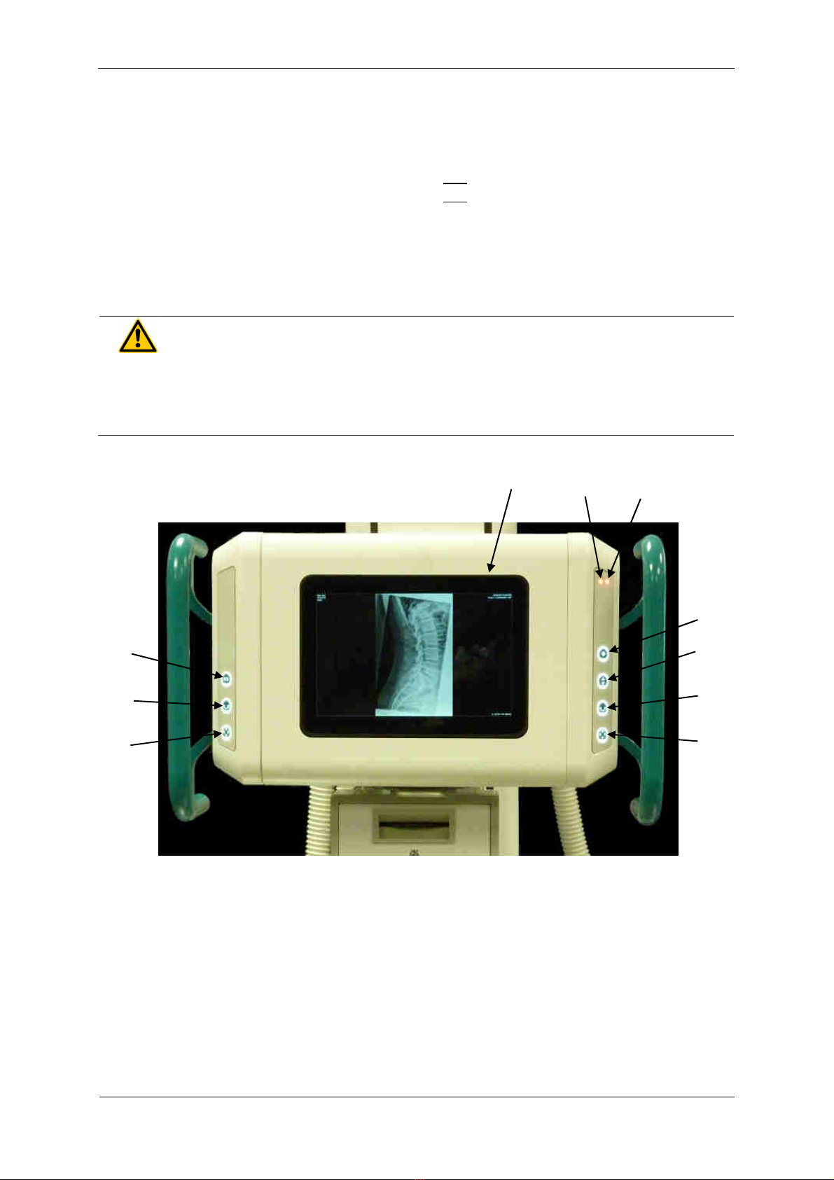
3.1.2 PROGNOST SH TOUCH
1 Touchdisplay of X-ray tube assembly
2 Brake release for horizontal movement of X-ray floor stand
3 Brake release for movement of X-ray tube assembly around the horizontal support arm axis
4 Brake release for vertical movement of X-ray tube arm and horizontal movement of X-ray floor stand
5 Brake release for vertical movement of X-ray tube arm and horizontal movement of X-ray floor stand
6 Brake release for movement of X-ray tube assembly around the horizontal support arm axis
7 Brake release for vertical movement of X-ray tube arm
8 Option: Brake release for transversal movement of X-ray tube arm (+230mm)
9 Option: Status-LED orange (if LED is on: X-ray tube arm is not engaged)
10 Option: Status-LED red (if LED on: X-ray flor stand is not engaged)
WARNING!
If th r d LED on th right m mbran k ypad lights up, th X-ray tub carri r
is not ngag d! In this stat no x-rays may b tak n. Th X-ray tub carri r
must first ngag in on of th positions (0 / ± 90° / ± 180°)!
Operation is from the front (operating side) of the X-ray head.
If the operating unit is equipped with handles, the electromagnetic lock of one or more movements
can be released by thumb pressure on the keys of the operating unit and the tube head can be
brought into the desired position.
6
5
1
2
3
4
7
6
5
8
9
10
PRS 500 X
Instructions for use
5066
-
0
-
8
002
PROTEC GmbH & Co. KG, In den Dorfwiesen 14, 71720 Oberstenfeld, Germany
1
von
40
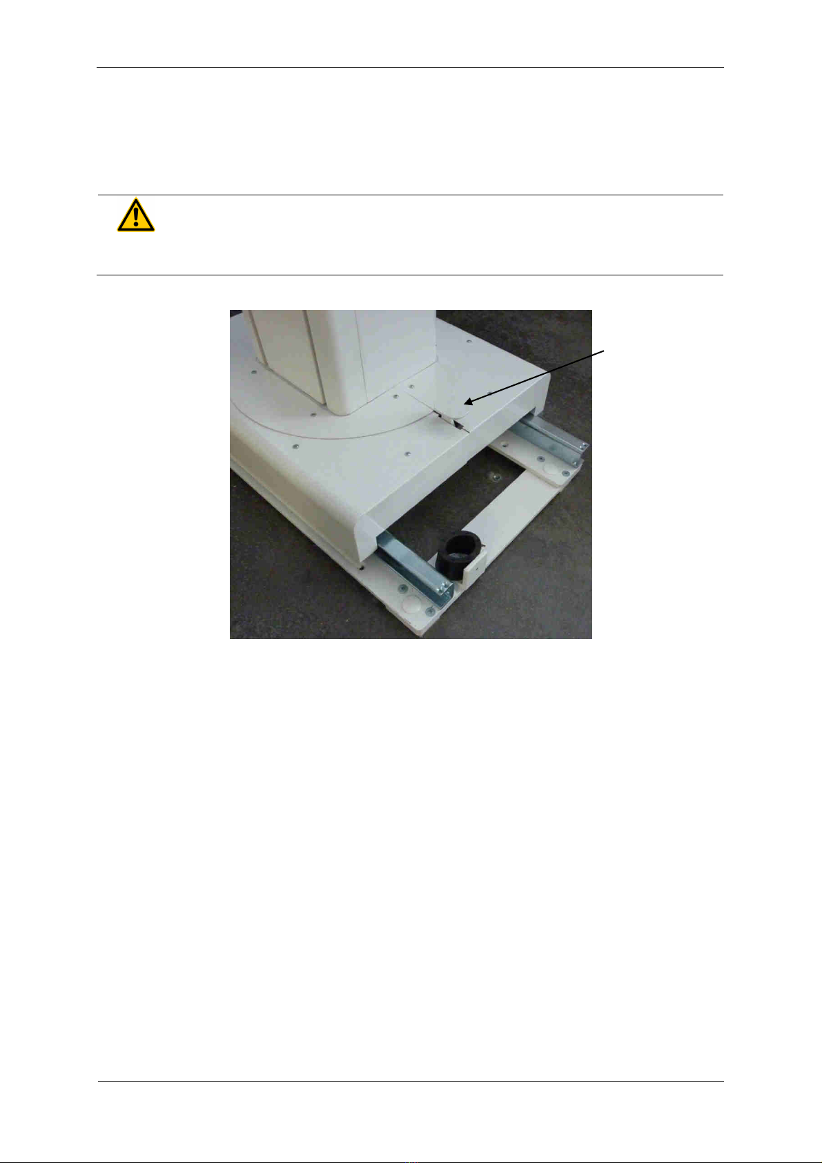
3.1.3 Foot p dal
To unlock the X-ray tube carrier, the foot lever (see Illustration Pos.1) must be operated downwards.
Hold the foot lever in this position and turn the X-ray tube carrier a little in the desired direction. For
further rotation, the foot lever does not have to be operated anymore. The detent in the new position
centers itself.
WARNING!
Th r is an incr as d risk of injury if th X-ray tub carri r is not ngag d!
Detailed information please find in the accompanying User Manual PROGNOST SH.
1

PRS 500 X
Instructions for use
5066
-
0
-
8
002
PROTEC GmbH & Co. KG, In den Dorfwiesen 14, 71720 Oberstenfeld, Germany
20
von
40
3.2 Control l m nts and d vic displays collimator
Figure collimator, may differ depending on the system.
Pos. 1 -> Collimator adjustment control; allows for manual opening and closing of collimator shutters
(transversely to table top).
Pos. 2 -> Scales; indicate the opening of collimator shutters (transversely to table top).
Pos. 3 ->Accessory rails (can be used for measuring phantoms).
Pos. 4 -> Light resp. X-ray field; corresponding to opening of collimator shutters.
Pos. 5 -> Light centering device; allows centering of the X-ray tube assembly with the bucky unit.
Pos. 6 –> Filter control for selection of additional filtration.
Pos. 7 -> Collimator adjustment control; allows for manual opening and closing of collimator shutter
(longitudinally to table top).
Pos. 8 -> Scales; indicate the opening of collimator shutters (longitudinally to table top).
Pos. 9 -> Collimator light switch; turns on collimator light.
Pos. 10 -> Measuring tape.
Detailed information please find in the enclosed User Manual collimator.
3.3 Control l m nts and d vic displays of X-ray tub
Detailed information please find in the enclosed User Manual of the X-ray tube.
3.4 Control l m nts and d vic displays of X-ray g n rator
Detailed information please find in the enclosed User Manual of the X-ray generator.
3.5 Control l m nts of Bucky, Grid ntity
Detailed information please find in the enclosed User Manual.
1
2
3
4/5
9
6
7
8
10
Other manuals for PRS 500 X
1
This manual suits for next models
1
Table of contents
Other Pro-tec Diagnostic Equipment manuals

Pro-tec
Pro-tec PRS 500 E User manual

Pro-tec
Pro-tec PROGNOST C User manual

Pro-tec
Pro-tec PRS 500 F User manual

Pro-tec
Pro-tec PRS 500 B User manual

Pro-tec
Pro-tec PROGNOST XP User manual

Pro-tec
Pro-tec PRS 500 B User manual

Pro-tec
Pro-tec PRS 500 E Instruction sheet

Pro-tec
Pro-tec PRS 500 F User manual

Pro-tec
Pro-tec PRS 500 F User manual

Pro-tec
Pro-tec 6000CCO Installation and operation manual


