Prodeco Technologies Mariner User manual

Some of the content of this manual may differ from
your bicycle depending on the options of the bicycle
and what your dealer provided.
© 2013 PRODECO TECHNOLOGIES. All rights
reserved. PRODECO TECHNOLOGIES and the
PRODECO TECHNOLOGIES logo are trademarks of
PRODECO TECHNOLOGIES. Printed in USA.
USER GUIDE
2
2
20
0
01
1
13
3
3
IMPORTANT: ALUMINUM FRAME. NOT INTENDED
FOR ABUSIVE RIDING. DO NOT JUMP OR HIT
CURBS AND AVOID IMPACTS. INSPECT FRAME
FOR FRACTURES. SERIOUS BODILY HARM CAN
OCCUR IF MISUSED.
SEE MANUAL FOR ADDITIONAL INFORMATION.

2
Table of Contents
1) Chapter 1: Introduction ……………………………………………………………………………………………….. 4
a. About this manual ………………………………………………………………………………………………….. 4
b. Important notices ……………………………………………………………………………………………………4
c. General warning …………………………………………………………………………………………………….4
d. A special note to parents ………………………………………………………………………………………….. 5
2) Chapter 2: Getting Started …………………………………………………………………………………………… 5
a. Unpacking your box ……………………………………………………………………………………………….. 5
b. Folding and unfolding ……………………………………………………………………………………………… 5
c. Familiarize yourself with your bicycle’s parts …………………………………………………………………… 6
d. Contents of the box ………………………………………………………………………………………………... 6
e. A guideline of your Mariner tool set ……………………….…………………………………………………... 6
f. Registering your new bike ………………………………………………………………………………………… 6
3) Chapter 3: Basic Instructions ……………………………………………………………………………………….. 7
a. Bicycle fit ……………………………………………………………………………………………………………. 7
b. Adjusting the saddle …….…………………………………………………………………………………………. 7
c. Adjusting the handlebar stem ………………………………………………………………………….…………. 8
d. Your local electric bicycle and bicycle laws …………………………………………………………………..….8
e. Safety first …………………………………………………..………………………………………………………. 9
f. Mechanical safety check ………………………………………………….………………………………………. 9
g. Before your first motorized ride ……………………………………………..……………………………………. 10
h. First motorized ride ……………..…………………………………………………………………………………. 10
i. Riding an electric bicycle …………………………………………….……………………………………………. 10
j. Using your twist throttle …………………………………………………………………………………………….10
k. Using your brakes …………….…………………………………………………………………………………….11
l. Pedaling ……………………….……………………………………………………………………………………. 11
m. Watching for obstacles around you ……………………………………………………………………………….11
n. Safe riding in various conditions ……………………………………………………………………………….….11
o. Charging your battery ……………………………………..………………………………………………………. 11
4) Chapter 4: Safety ………………………………………………………………………………………………………. 12
a. The basics ………………………………………..………………………………………………………………….12
b. Riding safety ………………………..……………………………………………………………………………….12
c. Wet weather riding ………………………………………………………………………………………………….13
d. Reflectors ……………………...……………………………………………………………………………………. 13
e. Night riding …………….…………………………………………………………………………………………….13
f. Adding accessories ……..…………………………………………………………………………………………. 13
5) Chapter 5: Perfect Fit and Ride ……………………………..………………………………………………………. 13
a. The basics …………………...……..………………………………………………………………………………. 13
b. Frame size ………………………..……………………………………………………………………………...….14
c. Recommended sizing ……………..………………………………………………………………………………. 14
d. Control position adjustments ………………………..……………………………………………………………. 14
e. Brake lever height adjustments ………………………..…………………………………………………………. 15
f. Suspension fork adjustment ………………………..……………………….……………………………………. 15
6) Chapter 6: Tire, Tube, Wheel or Axle Repair ……………………………………………………………………… 15
a. Removing the front motor wheel ………………………..………………………..………………………………. 15
b. Installing the front motor wheel ……………………..…………………………………...…………………….….15
c. Removing and installing the rear wheel ……………………..………………………………..…….………..…. 16
d. Replacing a tube or tire …………...………………………………………………………………………………. 17
7) Chapter 7: Maintenance and Replacement ………...………………………………………………………………18
a. Keeping your bike clean ………………..………………..………………………..……………………………….18
b. Avoid scratching your bike …………………..…………..………………………..……………………………….19
c. Brake bed-in and adjustments ………………………………………..…………..……………………………….19
d. Brake pad replacement ………………………………….………………………..………………………………. 21
e. Wheel check ………………………………..……………..………………………..……………………………….22
f. Lubricating ………………………..…………………………….…………………..………………………………. 22
g. Crankset …………………………………….……………..………………………..……………………………….22
h. Pedals ……………………………………………………..………………………..………………………………. 22
i. Headset …………………………………..………………..………………………..……………………………….22
j. Maintenance schedule …………………………….……..………………………..……………………………….22
k. Torque specifications for common parts ……………....………………………..………………………………. 23

3
8) Chapter 8: Battery Management …………………………………………………………………………………….. 23
a. About your battery ………………………………………..………………………..………………………………. 23
b. Removing the battery …………………..………………..………………………..………………………………. 23
c. Installing and locking the battery ……………………....………………………..………………………………. 24
d. Charging the battery ………………………..……………………………………..………………………………. 25
e. Storing the battery ………………………………………..………………………..………………………………. 25
f. Battery power indicator ………………………..………………………..………………………………………….25
g. Battery replacement ……………….……………………..………………………..………………………………. 25
h. Battery disposal …………………………………………..………………………..………………………………. 25
9) Chapter 9: Electrical Components ………………………..………………………………………………………… 26
a. HUB motor ………………………………………….……..………………………..……………………………….26
b. Brushless hall sensor controller ……………….………..………………………..………………………………. 26
c. Wiring harness ……………………………………………………………………..………………………………. 26
d. Throttle ………………………..………………………..………………………………………………………...….26
10) Chapter 10: Warranty Service and Repair ………………………………………………………………………….27
a. 2 year limited warranty …………………………………..………………………..………………………………. 27
b. Registering your bike ……..…………………….………..………………………..……………………………….28
c. Serial numbers and where to find them ………………..………………………..………………………………. 28
d. Registration card …………………..……………………..………………………..………………………………. 28
e. Part replacement procedure …………...………………..………………………..………………………………. 29
f. Contacting Prodeco Technologies ……………………..…………….…………..……………………………….29
11) Chapter 11: Specifications …………………….………………………………...……………………………………29
12) Chapter 12: Parts ……………………………………………………..…….…………………………….…………… 30

4
OPERATIONAL INSTRUCTIONS
Chapter 1: Introduction
Prodeco Technologies thanks you for your purchase of your new Mariner. Your bicycle is a high quality and environmentally
friendly light electric vehicle. This manual will serve to provide you with the information needed to operate, maintain and enjoyit
safely. Your electric bicycle should provide you with years of healthy enjoymentprovided you follow thesesteps.
For technical questions or customer service, please contact PRODECO TECHNOLOGIES at 800.943.6190 or e-mail us
at service@prodecotech.com.
a) About this manual
To prevent serious injury to yourself and others, and to prevent damage to the bicycle please read and understand these
instructions completely before operating your Prodeco Technologies Mariner. Your new bicycle is a powerful and reliable
electric bicycle. You should use caution and care while getting accustomed to your bicycle’s riding characteristics. The
following manual will provide basic instructions regarding your bicycle’s care and maintenance, battery management,
operating procedures, and other important information. You should read it thoroughly before riding your new bicycle for
the first time. If you have any questions that are not answered in this manual, contact your local authorized Prodeco
Technologies dealer or you can call customer service at 800.943.6190.
b) Important notices
Alwaysremovethekeyfromthe batterywhen yourbicycleisnotinuse,replacingacomponentorperformingmaintenance.
Makesure your electric bicycle is properlyfitted to you as described in Chapter 3 ―Basic Instructions‖.
Perform the mechanical safety check described in Chapter 3 ―Basic Instructions‖ section f ―Mechanical safety check‖
beforeeachride.
You should ride your Mariner as a traditional bicycle under pedal power priortoriding under motor powerfor the first time.
This willallow for the familiarization of how your Mariner rides and balances.
When riding under power for the first time, press the variable throttle very slowly only after pedaling to a slow speed to
understand the strength of the front motor’s performanceand grip onthe roadsurface.
Always applyfull front& rear brake lever pressure when attemptingtomount or dismount the bicycle.
When attempting to mount ordismount the bicycle,thekeyshouldbeinthe offpositionon thebattery.
Please read the battery pack and detailed charging instructions found in Chapter 8 ―Battery Management‖ before
chargingthe batterypackfor thefirst time.
Youshould fullychargethe Li-ionLiFEPO4 batteryaccording tothe charginginstructions beforeyour first ride.
Youshouldalwaysfullycharge yourLi-ionLiFEPO4 batteryevery10miles regardlessof the amountof smalltripdistances.
YoushouldalwaysfullychargeyourLi-ionLiFEPO4 batterypack after each round tripride exceeding 7.5miles.
Always storethebatterypackinacool and dryplace.
During periods of prolonged storage, the battery pack should be charged at least once every 6 months at a minimum of
60%orevery3 months at40%.Donotchargehigherthan60%whenstoring.
Your Mariner can be ridden as a traditional bicycle; it is strongly recommended that you also assist with pedaling when
ridingwhichcangreatlyincrease the distancebetweenbatterycharges.
When ridingunder power, you canenhancedistancein between charges byholdingthe throttleat 10% belowfullthrottle.
When riding under power, add as much non-powered coasting (similar to traditional pedaling) byreleasing the throttle and
allowingthebicycletofreelycoastunderitsownmomentum.Thiswillgreatlyincreasethe distancebetweencharges.
\
Familiarize yourself with throttling (10% below full), pedaling and momentum coasting to optimize the distance being
available per charge. If planning a long trip, applying a combination of the 3 distance enhancing methods mentioned
above will allowfor anuninterruptedpowersupplyfortheentireride.
c) General warning
Like any sport, bicycling involves the risk of injury and damage. By choosing to ride a bicycle, you assume the
responsibility for that risk, so you need to know —and to practice —the rules of safe and responsible riding and of
proper use and maintenance. Proper use andmaintenance of your bicyclereduces risk of injury.
This Manual contains many ―Warnings‖ and ―Cautions‖ concerning the consequences of failure to maintain or inspect
your bicycle and of failure to follow safe cycling practices.
WARNING: This image followed by the word WARNING indicates a potentially hazardous situation that,
if not avoided, could result in serious injury or death.
CAUTION: This image followed by the word CAUTION indicates a potentially hazardous situation, which,
if not avoided, may result in minor or moderate injury, serious, damage to the bicycle or the voiding of your
warranty or is an alert against unsafe practices.
Many of the Warnings and Cautions say, ―you may lose control and fall‖. Because any fall can result in serious injury or
even death, we do not always repeat the warning of possible injury or death. Because it is impossible to anticipate every
situation or condition that can occur while riding, this Manual makes no representation about the safe use of the bicycle
under all conditions. There are risks associated with the use of any bicycle which cannot be predicted or avoided, and
which are the soleresponsibility of the rider.

5
d) A special note to parents
The ProdecoTechnologies Mariner is intended forusebyadult riders only. Many state laws require electric bicycle riders to be
a minimum age of 16 with some states having minimum ages set as low as 10 years old and other states up to 18 years old
(at the time of the writing of this manual). As a parent or guardian, you are responsible for the activities and safety of your
minor child including the following of your state and local laws in regards to the riding of an electric bicycle by a minor (under
the age of 18).That includes, if your state allows a minor to ride, makingsure that your minor child can safelyride and control
allof the operations of the bicycle, and fullyunderstands allwarnings and cautions as indicated in this User Guide. Pleaseread
on if you have determined that your minor child can legally and safelyride and control all of the operations of the bicycle. That
includes makingsure that the bicycle is properlyfitted to thechild; that itis in good repair and safe operating condition; that you
and your child have learned and understand the safe operation of the bicycle; and that you and your child have learned,
understand and obeynot only the applicable local motor vehicle, bicycle and traffic laws, but also the common sense rules of
safe and responsible bicycling. As a parent or guardian, you should read and understand this manual. Beforeletting any child
ride the Mariner or any of Prodeco Technologies electric bicycles, review with them all warnings and cautions; as well as the
information on the proper usage of your battery pack, charger and bicycle. You must first confirm the laws, rules and
regulations regardingelectric bicycles in yourstate,cityandlocal municipality.
WARNING: Make sure that your child always wears an approved bicycle helmet when riding; but also
make sure that your child understands that a bicycle helmet is for bicycling only, and must be removed when not
riding. A helmet must not be worn while playing, in play areas, on playground equipment, while climbing trees, or
at any time while not riding a bicycle. Failure to follow this warning could result in serious injury or death.
Chapter 2: Getting Started
CAUTION: If you have purchased your bicycle by mail order or through a sales channel whereas your new
Mariner is still in the box, it is recommended you read Chapter 3 “Basic Instructions” section g “Before your first
ride” prior to your first ride. There may be additional adjustments required due to shipping by the freight carrier.
a) Unpacking your box
Your Mariner arrives fully assembled and only requires the insertion of the seatpost. You can learn how to insert the
seatpost and adjust for your height in Chapter 3 ―Basic Instructions‖ section b ―Adjusting the saddle‖.
The Mariner has been fully tested and adjusted prior to
being packed in the Heavy Duty double wall box with a
form fitting interior support system. To remove the Mariner
from it’s box, open the top flap of the box and remove the
top protection insert. Place one hand under the front
portion of the frame and the other hand under the center
of the frame. Pull up slowly and the bicycle will lift out of
the box. Remove the additional inserts (if attached to
bicycle) and set the bicycle down by balancing the bicycle
on the opened kick stand and both wheels. The kick stand
also performs as a crankset protector. To unfold the
bicycle, read the following paragraph, section b.
b) Folding and unfolding
Folding: your bicycle has the ability to fold for easy storing
and transporting. There are 2 quick release levers that will
allow the bicycle to fold into an area half of the original size.
The pedals can also be folded by squeezing the 2 metal tabs
on the outside edges of each pedal, pulling the pedal
outwards and then pushing the pedal down. To fold the
bicycle you will first un-latch the handle bar stem utilizing the
quick release lever on the handlebar steering tube. Slide the
tab up on thelever to releaseand unlockthelever. Pull on the
lever to now unlock the safety latch and to fold the handlebar
andsteeringtubedown.Second,standontherightsideofthe
bicycle (the crank set and chain side) and then unclasp the
frame hinge lever after turning the small safety release latch
up. You will now be able to fold the bicycle in half. When
picking up the bicycle once it has been folded, it is easy to lift
by placing one hand under the front portion of the frame and
one hand around the seat tube handle. If folding the bicycle is
to allow for the abilityto store in a closet or small space, after
folding you can roll the bicycle on its own wheel using the
saddlenosetoguideittothestoringarea.
Unfolding: your bicycle caneasilybeunfoldedinamatterof
seconds. Stand at the right side of the bicycle (the crank set
and chain side) and place one hand around the front portion
of the frame and one hand around the seat tube handle.
Open the frame to a straight position until the spring in the
hinge clasp lever locks the lever in place. Close the lever
completely and turn the hinge safety release latch down
(clockwise) to lock the frame hinge lever in place. Pull up the
handlebar/steering tube allowing for the handlebar stem’s
safety latch to lock the stem in place. Pull the quick release
lever towards the stem and confirm the spring loaded sliding
tab locks the lever in place. Pull on the lever to confirm it is
lockedinplace.

6
c) Familiarize yourself with your bicycle’s parts
d) Contents of the box
Check the contents of your box. Your new Mariner should include the following items in the box or your dealer should
have included these items with your purchase:
Mariner electric bicycle
Velo Plush GEL saddle
Prodeco Tech 36V 6Ah LiFEPO4 battery
36V LiFEPO4 charger
Charger power cable
2 keys
2 Piece Multi-use nickel plated tool set
2 cable ties (for future use)
e) A guideline of your Mariner tool set
The Mariner includes a multi-use tool set. This tool set includes all the tools necessary to make adjustments and service
your new bicycle. The only additional tool you will ever need is an 18mm wrench to remove the front wheel. All other
tools are included with the tool kit. The tool kit includes thefollowing tools:
Philips Screwdriver
Flat Screwdriver
2mm Hex Key
2.5mm Hex Key
3mm Hex Key
4mm Hex Key
5mm Hex Key
6mm Hex Key
8mm Socket
8mm Wrench
10mm Wrench
12mm Wrench
13mm Wrench
15mm Wrench
2 Tire Levers
f) Registering your new bike
For the warranty to take effect, you must register your new bicycle. Registration of your electric bicycle is the onlyway we
can acknowledge and verify the established owner. Your bicycle has 3 individual and unique serial numbers (frame,
motor and battery). Each serial number must be registered when filling out the registration form. The serial number on
the frame is located under the crank/bottom bracket portion of the frame. The serial number for the motor is found on the
motor’s side. The serial number for the battery is located on the barcode label adhered to the underside of the battery.
These numbers should be recorded and registered in case of warranty issues or theft. Please review Chapter 10
―Warranty Service and Repair‖ section c ―Registering your bicycle‖ how to register your Mariner. You can register by
either filling out the online registration form at www.prodecotech.com/register-your-bike/ or by sending the registration
card found in Chapter 10 ―Warranty Service and Repair‖ section d ―Registration card‖.

7
Chapter 3: Basic Instructions
a) Bicycle fit
It is very important your Mariner is properly adjusted for comfort and to avoid the possibility of losing control while riding. The
saddle and handlebar have adjustments available to allow riders from 5’ 6‖ to 6’ 6‖ to set the proper measurements allowing for
a safe and comfortable riding position. There are saddle height, rotation and distance to steering tube adjustments andalso a
handlebar height and rotation adjustment. If you plan to use your electric bicycle also as a traditional pedal bicycle, it is
recommended you adjust the saddle height to allow for a full leg extension when pedaling. The ball of your foot when resting
on the pedal should only allow for a slight bend at the knee when seated. Please review the following points in determining
how to makethe correct adjustments.The subsequent sections will assist you with making these adjustments.
1) Isyourbikeadjustedto yoursize?
2) Tocheck,seeChapter5―Perfect Fit and Ride‖.If yourbicycleisnotproperlyadjustedforyou,youmaylosecontrolandfall.
3) Isthesaddleattherightheight?Tocheck,seeChapter5―Perfect Fit and Ride‖ sectiona―Stand over height‖.
4) Are saddle and seat post securely clamped? A correctly tightened saddle will allow no saddle movement in any direction.
SeeChapter3―Basic Instructions‖ sectionb―Adjusting the saddle‖ for details.
5) Are the stem and handlebars at the right height for you? To check,see Chapter 5 ―Perfect and Ride‖ section c ―Handlebar
height and angle‖.Ifnot,seeChapter3―Basic Instructions‖ sectionc―Installingandadjustingthehandlebarstem‖.
6) Can you comfortably operate the brakes? If not, you have the abilityto adjust their angle and reach. See Chapter 5 ―Perfect
Fit and Ride‖ sectione―Brake lever height adjustments‖ fordetails.
7) Do you fully understand how to operate your new bicycle? If not, before your first ride, have your dealer or contact us to
explainanyfunctionsorfeatures thatyoudonotunderstandafterfullyreadingthismanual.
b) Adjusting the saddle
You have the ability to adjust the height of your saddle instantly via the quick
release clamp. There is also the ability to tilt the nose of the saddle up or down
and adjust your riding position to be further or closer to the handlebar. The latter
two require the use of the multi-use tool included with the purchase of your
Mariner. Please review the following details on adjusting your saddle.
To adjust the height of the saddle or remove the seat post, no tools are required.
The quick release lever is opened by pulling the lever away from the seat tube
allowing for the seat tube clamp to loosen the grip around the post. This will allow
you to raise or lower the saddle to the desired height. There is a minimum
insertion line on the seat post which must be followed and you must not extend
the seat post past this mark. It is also important the seat tube clamp is tightened
sufficiently around the seat post for it not to slide downwards after the quick
release lever is closed. This can be accomplished by tightening the quick release
nut clock wise which is located on the opposite end of the quick release lever.
WARNING: The seat post includes a minimum insertion mark. It is important you do not allow the seat
post to be clamped below this mark. This mark must be inserted into the frame pass the top of quick release
clamp. If clamping below this mark, it can cause the seat post to break, failure to follow this warning could
result in serious injury or death.
CAUTION: The seat tube quick release clamp must be checked for tightness to ensure the saddle will not
accidentally slide into the seat tube when riding. This can cause a rider to lose balance and may result in a fall.
To tilt the nose of your saddle upwards or downwards, you will need to use the 5mm hex key included with your multi-use
tool kit that came with your bicycle. The saddle mounting clamp attaches the saddle to the seat post via a front and rear
barrel nut and bolt. To bring the nose of the saddle down, loosen the rear bolt by 1 full counter clockwise rotation and tighten
the front bolt by 1 full clockwise rotation. Check for comfort and if the nose is still too high, attempt the abovestep again.
Continue to adjust by repeating the step above until the desired nose height is
established. If you prefer to raise the nose, you can follow the above step but in the
opposite direction (loosen the front bolt counter clockwise 1 rotation and tighten the
rear bolt clockwise 1 rotation).
Your saddle can also be adjusted to be closer or further away from the steering
tube/handlebar. This adjustment is minimal but allows a 7.5mm adjustment in either
direction from center mount (15mm total, close to 5/8‖). To adjust the saddle closer or
further, you must loosen the rear and front barrel nut and bolt set described in the
previous paragraph. Loosen both bolts by rotating a minimum of 2 times counter
clockwise. This will allow the clamp to slide in either direction on the saddlerails. You
must not allow the edge of the saddle mounting clamp to meet with the saddle rail
bends. The edge of the clamp must be a minimum of 5mm from the saddle rail
bends. Upon establishing the correct position, tighten the saddle mounting clamp
bolts 2 times inclockwise direction. Check for tightness of bolts and continue turning if
loose. Allbolts shouldbe tightened to 140 in*lb. (SEEPHOTO)
CAUTION: The saddle mounting clamp front and rear barrel nut and
bolt must remain tight at all times. Test saddle for looseness or play in the rotation of the nose. If saddle is
loose, tighten the bracket bolts to ensure the saddle will not accidentally rotate up or down when riding. Both
bolts should be tightened to 140 in*lb. If loose, this can cause a rider to lose balance and may result in a fall.
CAUTION: The edge of the saddle mounting clamp must have a minimum of 5mm of clearance from the
saddle rail bends. If the edge of the clamp is mounted to close the saddle rail bends and the rider does not
position themselves properly on the saddle, this could result in the rails becoming unstable due to the leverage
of the riders weight. The rails can bend and can cause a rider to lose balance and may result in a fall.

8
The Mariner includes a high quality aluminum alloy suspension seat post. The
pre-load firmness of the suspension travel can be adjusted (you will need to use
the 6mm hex key included with your multi-piece tool kit). To adjust the firmness,
remove the seat post as explained in the above section. Located at the base and
underside of the seat post is an adjusting cap. Loosen the cap counter clockwise
if you prefer to soften the ride (do not allow the thread of the cap to be exposed
past the end of the seat post). If you prefer to increase firmness, tighten the cap
clockwise until you reach the desired firmness level. (SEE PHOTO)
c) Adjusting the handlebar stem
The handlebar of the Mariner can be adjusted instantaneously for height
preference. Locate the quick release lever of the handlebar stem’s clamp and
open the lever away from handlebar stem. You can slide the handlebar up or
down to the desired height. Once the preferred height is established, close the
quick release lever to tighten the clamp. Check for tightness of the clamp and test
the handlebar for slipping in either the upwards or downwards position. If the
clamp is loose, open the quick release clamp lever and tighten the clamp bolt
found opposite the quick release lever. Tighten sufficiently allowing for the lever to
close properly and clamp the handlebar tight. Do not overextend the handlebar
past the minimum insertion mark.
CAUTION: The handlebarstemquick release clampmust bechecked for
tightness to ensure the handlebar will not accidentally slid into the steering tube
whenriding.This cancausearidertolosebalanceandmayresultinafall.
WARNING: The handlebar includes a minimum insertion mark. It is
important you do not allow the handlebar to be clamped below this mark. This
markmustbeinsertedintothe handlebar stem andnotbevisibleabovethequick
release clamp. If clamping below this mark, it can cause the handlebar to fall out,
failure to follow this warning could resultin seriousinjuryordeath.
d) Your local electric bicycle and bicycle laws
Your newMariner was designedtofollowthe federalguidelinestoestablishthe Mariner
as a traditional pedal power bicycle within most USA states and to be allowed to ride in
bicycle pathways. However, electric bicycle laws change often and you are responsible
to confirm legal status of the riding of your electric bicycle in bicycle pathways. Below is
areferencesectionontheUSAelectricbicyclefederalguidelines:
Electric Bicycle Laws (please contact your local transportation department for the
specific lawsin yourstateandcity regarding riding electricbicycles onbikepathways)
Prodeco Technologies offers the following information as guidance and does not
guaranteeorassureriderstheyarefollowingtherulesandregulationsoftheirstate.
Electric bicyclelaws mayvarybystateto state with moststates followingthe classification
of that by the CPSC (Consumer Product Safety Commission), DOT & NHSTA. Further,
the US NHSTA (National Highway Traffic Safety Administration) defines low-speed
electric bicycles (under 20mph) also as consumer products and not Motor Vehicles for
safety standards. The NHSTA adheres for the most part to the CPSC guidelines.
Weincluded reference below on how electric bicycles are perceived by the Federal
Government’s most important agencies. We do believe new regulation and rules will
apply in the future upon the electric bicycle becoming one of the standard forms of
transportationforthemasses.ProdecoTechnologies willcontinuetofollownewrulesand
guidance set forth by these agencies, always welcoming and adhering to the guidelines
theyfeelarerequiredtoassuresafetyfortheelectricbicyclerider.
On October 22, 2008, the Federal Highway Administration (FHWA) updated the Bicycle and Pedestrian Provisions of
Federal Transportation Legislationtomake technicalcorrectionsand clarifications.
Belowaretheimportantupdatesreflectingelectricbicycles:
Motorized Vehicle Use: In general, motorized vehicles are not permitted on non-motorized trails and pedestrian walkways funded
under Title 23. Exceptions to this general rule exist for maintenance vehicles; motorized wheelchairs; when State or local
regulations permit, snowmobiles; and electric bicycles (weighing under 100 pounds and a top speed of less than 20 miles per
hour); "and such other circumstances as the Secretary deems appropriate" (except the Recreational Trails Program which
specificallyprovides funds for motorized trails). In 2008, FHWA developed a Framework for Considering Motorized Use on Non-
motorizedTrailsandPedestrianWalkwaystoimplementthe"othercircumstances"provision.
Prodeco Technologies only offers electric bicycles that fall under the category of ―weighing under 100 pounds and a top speed of
less than 20 miles per hour‖. According to the DOT and NHSTA, Prodeco electric bicycles meet the exception of Motorized
Vehiclesandthereforecanberiddenonnon-motorizedtrails andbikepathspermittingstateandlocallaws.
Framework for Considering Motorized Use on Non-motorizedTrails and Pedestrian Walkways under 23 U.S.C. § 217
The purpose of this document is to provide guidance to Federal HighwayAdministration (FHWA) division offices and a consistent
framework fordeterminingwhentopermitanexceptionformotorized useonnon-motorized trails andpedestrian walkwaysunder
23U.S.C.§ 217(h)(5).Therelevantlegislationreads as follows:
23 U.S.C. § 217. Bicycle Transportation and Pedestrian Walkways (h) Use of Motorized Vehicles.--Motorized vehicles may
not be permitted on trails and pedestrian walkways under this section, except for-- (1) maintenance purposes; (2) when snow
conditions and State or local regulations permit, snowmobiles; (3) motorized wheelchairs; (4) when State or local regulations
permit,electric bicycles;and(5)suchothercircumstancesastheSecretarydeemsappropriate.
(j)Definitions.--Inthissection,thefollowingdefinitionsapply:

9
(2)Electric bicycle.--The term "electric bicycle" means any bicycle or tricycle with a low-powered electric motor
weighing under100pounds,with atopmotor-powered speed notinexcessof 20 milesperhour.
(4) Wheelchair.--The term "wheelchair" means a mobility aid, usable indoors, and designed for and used by individuals with
mobilityimpairments,whetheroperatedmanuallyormotorized.
Theabove23U.S.C. §217 offersdirection thattheProdecoElectricBicyclesare allowedonbike-paths(non-motorizedtrails)due
toProdeco electric bicyclesfallingundertheclassificationoflessthan100poundsandunder 20mph.
HR727
SECTION1, CONSUMER PRODUCT SAFETY ACT
TheConsumerProductSafetyAct(15U.S.C.2051etseq)isamendedbyaddedattheendofthefollowing:
LOW-SPEED ELECTRIC BICYCLES
SEC. 38.(a) Notwithstanding any other provision of law, low-speed electric bicycles are consumer products within the meaning of
section3(a)(1)andshallbesubjecttotheCommissionregulationspublished atsection1500.18
(a)(12)andpart1512of title16,CodeofFederalRegulations.
(b) For the purpose of this section, the term `low-speed electric bicycle' means a two or three-wheeled vehicle with fully operable
pedals and an electric motor of less than 750 watts (1 h.p.), whose maximum speed on a paved level surface, when powered
solelybysuchamotorwhileriddenbyanoperator who weighs170pounds,islessthan20mph.
(c) To further protect the safety of consumers who ride low-speed electric bicycles, the Commission may promulgate new or
amendedrequirementsapplicabletosuchvehiclesasnecessaryandappropriate.
(d) This section shall supersede any State law or requirement with respect to low speed electric bicycles to the extent that such
StatelaworrequirementismorestringentthantheFederallaworrequirementsreferredtoinsubsection(a).
SEC.2.MOTORVEHICLESAFETYSTANDARDS.
For purposes of motor vehicle safety standards issued and enforced pursuant to chapter 301 of title 49, United States Code, a
low-speed electric bicycle (as defined in section 38(b) of the Consumer Product Safety Act) shall not be considered a motor
vehicleasdefinedbysection30102(6)oftitle49, United StatesCode.
Local BicycleLaws
Most states have their own set of bicycle laws regarding traditional pedal powered bicycles. With most states recognizing electric
bicyclesastraditionalpedalpoweredbicycles you must learn the applicable laws in your area. Your Department of Transportation
or Cycle Clubs in your area will have the details involving riding a bicycle in your area and your city’s bike pathways. Requirements
for riding will change depending on location. Most cities require LED lights, hand signals, riding on the correct side of the road,
riding behind and not parallel to other cyclist, etc…
e) Safety first
It is important you follow your local bicycle laws but also it is important you ride safely. Below are examples of understanding
how to ride your new Mariner safely. Always wear an approved helmet when riding your bike, and follow the helmet
manufacturer’s instructions for fit, use and care of your helmet.
Do you have all the other required and recommended safety equipment for your area? It’s your responsibility to familiarize
yourself withthe laws of the areas where you ride,and to complywith allapplicable laws.
Do you know how to correctly check your wheel axle nuts? Do you understand proper braking techniques? Is your saddle
properly adjusted? How do you power your new electric bicycle?These are all questions you should have the answers to prior
to riding for the first time. This USER GUIDE will answer most of the questions you have in regards to your new bicycle and
assist you in ensuring your electric bicycle remains safe to ride. You should first read the USER GUIDE in its entirety and
familiarize yourself with your new bicycle prior to riding.
For further safetyguidelines,please read Chapter 4: Safety
f) Mechanical safety check - Check the condition of your bicycle before everyride.
Nuts, bolts and straps: Makesure nothing is loose. Lift the front wheel off the ground by two or three inchesthen let it
bounce on the ground. Anything sound, feel or look loose? Do a quick visual and tactile inspection of the whole bike. Are
there anyloose parts or accessories? If so, secure them. If you’re not sure, ask someone with bike experience to check.
Tires and Wheels: Make sure tires are correctly inflated, see Chapter 6. Check by putting one hand on the saddle,
and the other on the intersection of the handlebars and stem, then bounce your weight on the bike while looking at tire
deflection. Compare what you see with how it looks when you know the tires are correctly inflated; and adjust if necessary.
Are the tires in good shape? Spin each wheel slowly and look for cuts in the tread and sidewall. Replace damaged tires
before riding the bike. Spin each wheel and check for brake clearance and side-to-side wobble. If a wheel wobbles side to
side even slightly, or rubs against or hits the brake pads, take the bike to a qualified bike shop to have the wheel trued.
Brakes: Check the brakes for proper operation. Squeeze the brake levers. Are the brakes properly releasing? All
control cables seated and securely engaged? Do the disc brake pads grasp the rotors within an inch of brake lever
movement? Can you apply full braking force at the levers without having them touch the handlebar? If not, your brakes
need adjustment. Do notride the bikeuntil thebrakes are properlyadjusted.
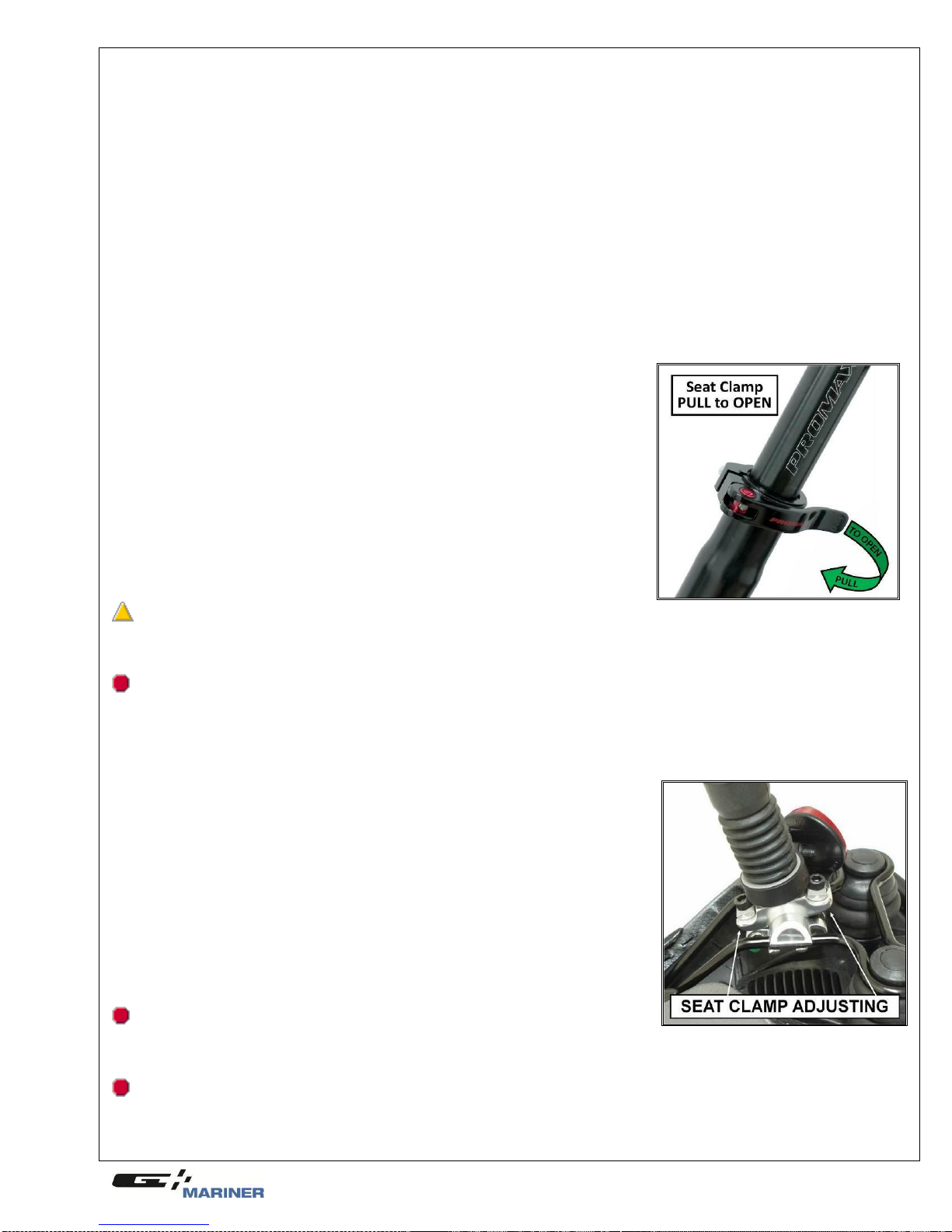
Quick Releases: Make sure seat post, stem, rear axle & frame quick release levers are properly adjusted and all
are in the locked position.
Handlebar and saddle alignment: Makesure the saddle and handlebar stem are parallel to the bike’s center line, clamped
andboltstightenedenough so that you can’t twist them out of alignment. If not, align and tighten them.
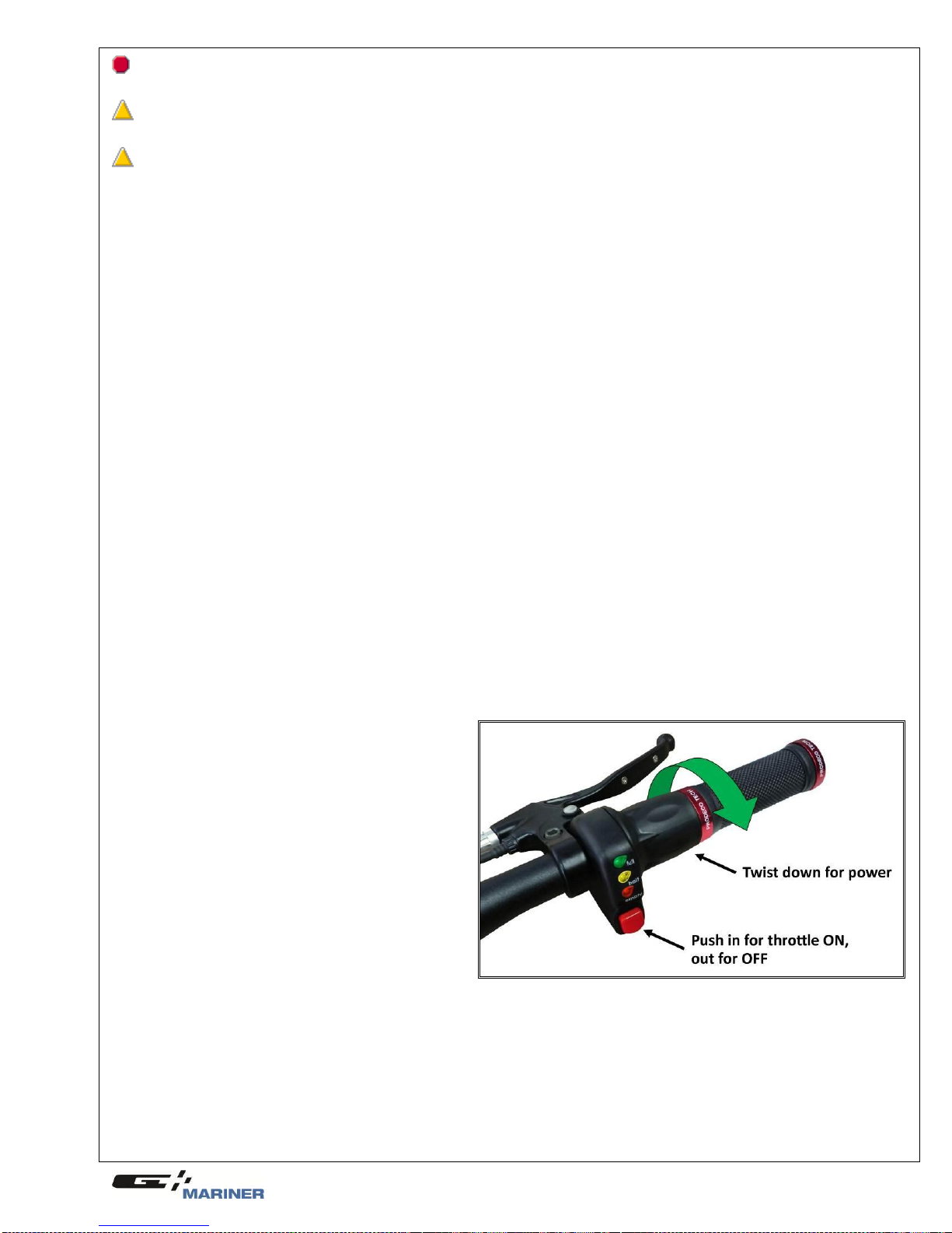
Handlebar ends: Makesurethelefthandlebargripandrightthrottlegriparesecureandingoodcondition.Ifnot,replacethem.
Battery Pack Attachment: Ensure your battery pack is firmly attached to your bicycle before riding. To test battery
attachment, pull up on the battery pack handle after battery is locked in place. If attached properly you will not be able to
slide the battery off the bike. If not, the battery pack will slide off the bike.

10
CAUTION: The braking of your bicycle is one of the highest concerns in safety. Proper brake lever
mounting and cable adjustment is crucial for your brakes to work properly.
WARNING: All Quick release levers must be closed and the clamps or axles tight. One loose quick
release lever can cause the rider to lose control and cause serious injury or death.
WARNING: Loose or damaged handlebar grips or extensions can cause you to lose control and fall.
Unplugged handlebars can cut your body, and can cause serious injury in an otherwise minor accident.
g) Before your first motorized ride
Before your first ride study this manual in its entirety. Make sure you are comfortable and confident when sitting on the
bicycle. If an adjustment does not feelright or something feels loose, check to ensure you are properly fitted to the bike and
do a mechanical safety check as explained in the previous section. Make sure you fully charge your battery with the
appropriate charger included with your bicycle. Be sure to firmly attach the battery to the bicycle. Try to slide the battery off
the bike bythe battery handle to confirm proper installation. Read Chapter 3, section h. (the following section) again.
h) First motorized ride
When you buckle on your helmet and go for your first familiarization motorized ride on your new bicycle, be sure to pick a
controlled environment, away from cars, other cyclists, obstacles or other hazards. Ride to become familiar with the
brake levers against throttling, variable throttle performance while pedaling your new bike and not pedaling. The first
motorized ride should be initially pedaling and then slowly pressing down on the throttle to feel the engagement of the
HUB motor. Familiarize yourself with the sensation of power.
Familiarize yourself with the braking action of the bike. To test the brakes at slow speed, shift your weight
toward the rear and gently apply the brakes, rear brake first. Sudden or excessive application of the front
brake could pitch you over the handlebars. Applying brakes too hard can lock up a wheel, which could
cause you to lose controland fall (see section j.).
Your bike has a front suspension system, familiarize yourself with how the suspension responds to braking
application and rider weight shifts.
Check out the handling and response of the bike; and check the comfort.
If you have any questions, or if you feel anything about the bike is not as it should be, take the bike back to
your dealer for advice or contact Customer Service at Prodeco Technologies.
i) Riding an electric bicycle
Riding an electric bike is similar to riding a non-electric bike but there are some differences to note. An electric bike is
slightly heavier and requires more time to stop due to higher traveling speeds. Your bike is also equipped with a powerful
motor that provides a boost noticeable when starting from a stop. The boost is exhilarating, but you must be comfortable
with the sensation before riding in crowded or congested areas. To maximize battery life, assist with pedaling, engage
throttle to 90% or less and add considerable coasting with no throttle to your riding. Your battery is a finite resource and
proper riding techniques will prolong its distance per charge.
j) Using your twist throttle
The variable throttle on your Mariner was designed to
allow you the ability to choose the speed to ride at and
determine the amount of torque off the line. The throttle
operates similar to an automobile; the twisting of the
throttle mimics the depressing of the accelerator. The
throttle is located on the right side grip and considered a
half twist throttle. It is a half twist, as only the inside
portion will twist to power the bicycle. The grip itself will
not twist. Using youforefinger and thumb, youcan safely
twist the throttle to propel the bike forward. A half twist
throttle is used to avoid accidentally twisting the full grip
when mounting and dismounting the bicycle. Your
throttle also includes a Power ON and Power OFF
button. It is the red button located underneath the LED
lights. Depressing the button in activates the throttle and
pressing the button out will deactivate the throttle. The
ON/OFF button isforfurthersafety. Thereisalsoan
LED set of lights which assist in determining the amount of batterystorage capacityremaining. This is discussed in further detail
later in themanual. Throttling is an importantfactor with anyelectric bicycle andthe distance of traveling available per charge. The
higher the speed, the less distance per charge, the faster you accelerate off the line, the less distance per charge. If there are
multiple stops and take offs, this also affects the range of distance per charge. It is recommended you become accustomed to
your style of riding and adjust the style depending on distance needed per charge. For example: if you are planning a short local
trip, full throttle at takeoff and top speed will not be an issue due to your ability to be able to recharge the battery prior to the next
trip. If you are planning a longer trip, 10-15 miles or more, it is suggested you add pedaling, hold throttle back 10% and whenever
possible allow the bicycle to coast under no power. Coasting under no power is similar to riding a traditional pedal powered
bicycle. When riding, a rider will pedal for a few seconds and then stop pedaling, allowing the bike to coast with no power being
used.Thiswillgreatlyincreaseyourdistancebetween charging.(SEEPHOTO)

11
k) Using your brakes
Your Mariner is equipped with a high performance ―Tool Free‖ adjusting Avid BB5 front Disc Brake and rear V-Brake
system. This brake system allows your new Mariner to stop quickly and accurately. An oversized Avid HS ―Heat Shedding‖
stainless steel disc rotor is utilized for the front axle for increased heat dissipation.When properly adjusted, the Mariner high
performance brake system offers tremendous stopping power. Prior to leaving the factory, the Mariner brakes were
adjusted tight and properly tested. Due to cable stretching from new condition, your brakes may need to be readjusted
within a few weeks of riding. Please refer to Chapter 7 ―Maintenance and Replacement‖, section c ―Brake adjustments‖ to
adjust your brakes for optimum performance. When braking, both brake levers should be applied simultaneously. Your left
brake lever manages your front brake and your right brake lever manages your rear brake. You should first become
accustomed with the stopping power of each brake (front & rear). Test each brake separately in a controlled environment
for their ability to stop the bicycle. Front brakes when locked can cause the rear wheel to come off the ground and the rider
can be thrown off the bicycle. In emergency situations, apply pressure to each brake lever, shift your weight to the back of
the bicycle and only attempt to use full force on the front brakes when the bicycle is not stopping quickly enough. Always
keepa safe distance between vehicles, pedestrians and other bicycle ridersfrom yourself.
WARNING: Locking the front wheel during braking can cause the rear wheel to lift off the ground and
throw the rider off the bicycle. Both brake levers should be applied simultaneously. In an emergency situation
shift your weight to the back of the bicycle. Locking the front wheel can cause the rider to lose control, be
thrown off the bicycle and cause serious injury or death.
l) Pedaling
Pedaling your Mariner is the same as pedaling a traditional bicycle. It is recommended youadd pedaling to the power of the
bicycle to enhance the distance per charge. The Mariner is a single speed bicycle and has the ratio of a 48T front chain ring
(sprocket) against a 16T rear freewheel which is designed to offer an easy pedaling pace atspeeds up to 11 MPH. With the
use of the throttle, any speed over 15MPH requires little effort in pedaling with the almost impossibility to pedal fast enough
to catch up with the motor. If not using the motor and pedaling under the rider’s own power, the ratio of 48T to 16T on a 20‖
rim can feel slightly difficult if on an incline. It is recommended on steep inclines, the rider utilizes the throttle to assist in
powering the bicycle up the incline. If a rider’s style of riding is throttle only with no pedaling, distance per charge will be
decreased and upon a steep incline, the rider may be required to assist the motor by pedaling to power up the incline.
m) Watching for obstacles around you
Your new Mariner travels at higher speeds than most riders are accustomed to, when compared to pedaling a traditional
bicycle. It is very important you are aware of your surroundings and obstacles which may appear near you. You must watch
the road surface you are traveling on which could cause the tires to slip or cause a flat. Examples are soft shoulders, rocks, pot
holes, uneven paths, grates, construction sites. Due to the higher rate of speed when riding under motor power versus
pedaling, objects will advance into your path at a faster rate. Pay attention to other riders in your area, automobiles,
motorcycles, pedestrians, poles, intersections and road signs to name a few. The Mariner resembles a traditional bicycle and
peoplewalking,driving or standing maynot realize youare on a motor powered vehicle and misjudgeyour traveling speed.
WARNING: Hitting a pot hole, soft shoulder or other road deviation may cause you to lose control, be
thrown and cause serious injury or death.
n) Safe riding in various conditions
Riders may find themselves riding in a condition they did not plan on encountering. It is important your new Mariner is
maintained properly for optimum performance. Please read Chapter 7 on the details required to keep your electric bicycle at its
best. An unexpected rain storm, snow flurry or night ride could arise during a day’s trip and you should always be prepared.
Please readChapter 4 on Safety, so uponencountering anunexpectedridingcondition, youwill be confident and ready.
o) Charging your battery
The Mariner’s battery system is the safest and latest technology in Lithium Ion battery cells and was designed to be
easily charged. Chapter 8 offers a detailed explanation on battery management but the following information is a basic
guide in charging your battery. The battery is a removable device and can be charged on or off the bicycle. If removing
the battery to charge it, please follow these instructions.
Locate the key ignition on the battery and turn the key in a counter clockwise rotation to the ―UNLOCK‖
position. You must push the key in to turn from the ―OFF‖ position to the ―UNLOCK‖ position.
Grab the handle at the back of batteryand carefullypull towards the back of the bicycle to slide off.
The batteryis now transportable and can be charged away from the bicycle when in ―UNLOCK‖ position.
For charging, please review the following instructions.
Lift up the handle of the battery to access the RCA charging input.
Insert the charging plug from the charger into the battery’s RCA charging input.
Insert the charger’s power cord into a wall outlet.
The charger’s LED light will light RED while the charger is charging the battery.
The charger’s LED light will light GREEN upon the battery being fully charged.
There is also a battery indicator for checking a full charge. Press the indicator button to display the battery’s
energy storage. The indicator is located on top of the battery.
Once the battery is fully charged, you should discontinue charging and remove the charger.
Unplug the charger’s power cord from the wall and remove the charging plug from the battery.
You are ready to install the battery pack back onto your bicycle.
To install the battery, first align the bottom of the battery with the batterybase rail.
Once aligned, slide the battery firmly into the battery base and until the battery base terminals insert into the
battery’s terminal outlets. The battery’s locking slots must slide properly onto the mount’s 3 metal tabs.
Once the battery is properly slid into place, you can then turn the key to the ―ON‖ position.
The LEDs on the throttle in the ―ON‖ position will display a charged battery’s energy capacity.

12
Chapter 4: Safety
The manual has detailed safety riding methods. In this chapter we will further discuss additional safety guidelines.
a) The basics
Below is a safetyguideline according to the CPSC (US Consumer Product Safety Commission) in regards to riding a bike.
Always wear a helmet to help prevent head injuries.
Observe all traffic laws andsignals, just as automobiles must do.
Don’t ride double or attempt stunts.
Ride near thecurb in the same direction as traffic.
Find alternate routes, rather than ride through busy intersections and heavyor high-speed traffic.
Walk -- don't ride -- your bicycle across busy intersections and left turn corners.
Avoid riding in wet weather. When wet, handbrakes may require a long distance to stop.
Avoid riding in the dark. If you do, be sure the bike is equipped with a headlight, a taillight and reflectors.
Apply retro-reflective trim to clothing, or wear reflective vests and jackets.
Avoid loose clothing or long coats that can catch in pedals or wheels. Leg clips or bands keep pants legs
from tangling in the chain.
Avoid crossingraised sewer grates.
Regular maintenance is essential for safe riding. Refer to the maintenance recommendations. If you do not
have basic mechanical skills, an authorized dealer should perform repairs and maintenance.
Align (or "true") wobbly wheels for better control. Spokes also may need adjustment.
Replace all missing, damaged, or worn parts; for example, brake pads, chainguards, chain links, spokes,
screws and bolts, handlebar grips.
Tighten and/or adjust loose parts.
Periodically inspect frame, fork, spindles and other components for cracking.
Parts should be adjusted to manufacturer's torque specifications.
Inflate tires to recommended pressure, and replace worn tires.
Lightly oil and clean moving parts. Keep oil off rubber.
Keep bicycle indoors when not in use.
b. Riding safety
Below are guidelines according to the NHSTA (National Highwayand Traffic SafetyAdministration) on bicycle safety.
Protect Your Head: Wear a Helmet - Never ride a bicycle without wearing a properly fitted helmet. Helmets are
proven to be 85-88 percent effective in preventing traumatic brain injury, the primary cause of death and disabling
injuries resulting from cycling crashes. Wear a helmet that meets the U.S. Consumer Product Safety Commission
(CPSC) standard (see inside of helmet for presence of a label).
Assure Bicycle Readiness: Ensure Proper Size and Function of Bicycle - Make sure the bicycle fits you: Stand
over the top of the Mariner bicycle –there should be minimum 3 inches of clearance from the frame bar. Seat height
—as previously mentioned, with the ball of your foot on the pedal, the fully extended leg should have a slight bend.
Check all parts of the bicycle to make sure they are secure and working well: The Handlebar should be firmly in place
and turns easily. The wheels must be straight and secure; the quick release rear axle must be secured.
Stop It: Always Check Brakes Before Riding - Always control your speed by using your brakes. Apply the rear
brake slightly before the front brake. Always keep your brakes adjusted. If you cannot stop quickly, adjust your brakes.
Review Chapter 7 ―Maintenance and Replacement‖ section c ―Brake adjustments‖ to adjust the brakes. When your
hand brake levers are fully applied, they should not touch the handlebars. Ride slowly in wet weather and apply your
brakes earlier, it takes more distance to stop.
See and Be Seen - Wear clothes that make you more visible. Always wear neon, florescent, or other bright colors
when riding a bicycle.
Avoid Biking at Night - It is far more dangerous to bicycle at night than during the day. The Mariner requires LED
lights for night time riding. If you must ride at night, you should also do the following: wear retro-reflective clothing or
material, not just white or florescent, especially on your ankles, wrists, back, and helmet. Only ride in areas familiar to
you. Brightlylit streets are best. Always assume you arenotseen bya driver. Children should NOT ride at night.
Go With the Flow: The Safe Way is the RIGHT Way - Ride on the right side in a straight, predictable path. Always
go single file in the same direction as other vehicles. Riding against traffic puts you where motorists don't expect you.
Theymaynot see you, and may pull across your path, or turn into you.
Check for Traffic: Always Be Aware of the Traffic Around You - Over 70 percent of car-bicycle crashes occur at
driveways or other intersections. Before you enter any street or intersection, check for traffic. Always look left-right-left,
and walk your bicycle into the street to begin your ride. If you are already in the street, always look behind you for a
break-in traffic, then signalbefore going left or right. Watch for left or right turning traffic.
Learn Rules of The Road: Obey Traffic Laws - Bicycles are considered vehicles. Bicyclists must obey the same
rules as motorists. Read your State drivers handbook, and learn and follow all the traffic signs, laws, and rules for
operating a vehicle on the road. Always signal your moves. Be courteous to pedestrians and other vehicle operators.
Never wear headphones while riding as they impair your ability to hear traffic. Become familiar with the
accommodations that are available for bicyclists in your area. These include bicycle lanes and routes as well as off-
road paths. Take advantage of these whenever possible.

13
“Drive” with Care: Share the Road - When you ride, consider yourself the driver of a vehicle and always keepsafety
in mind. Choose to ride in the bike lane, if available. If the roadway or bike lane is wide, ride to the right; if the lane is
narrow, you may choose to ride in the middle of the lane. Take extra precautions when riding on a roadway. Bicycles
are smaller than automobiles, and don’t protect the operator like an automobile. You should: Make eye contact, smile,
or wave to communicate with motorists. Courtesy and predictability are a key to safe cycling; be considerate and
aware of motorists and pedestrians. Learn to anticipate their actions. Remember, pedestrians have the right of way;
Ride far enough awayfrom the curb to avoid the unexpected from parked cars (i.e. opening doors or drivers pulling out
without checking); Keep control of your bicycle: look behind you while maintaining your bicycle in a straight path; be
able to ride with one hand on the handlebars and signal a turn. (Practice these skills in a parking lot); Always look over
your shoulder, and if possible, signal before changing lanes; Make sure that books, clothes, and other items are
securely attached to the bicycle or carried in a backpack; and Use bells, horns, or your voice to alert pedestrians and
bicyclists that you are approachingor passing.
Stay Focused: Stay Alert - Never wear headphones; they hinder your abilityto hear traffic. Always look for obstacles
in your path (potholes, cracks, expansion joints, railroad tracks, wet leaves, drainage grates, or anything that could
make you fall). Before going around any object,scan ahead and behind you for a gap in traffic, signal your intentions to
move, and then follow through with your intentions. Be aware of the traffic around you. Ride defensively. Use extra
care when riding in wet weather, ice, frost, or snow. Slow your speed and allow extra time and space to stop. Use
extra care when crossing bridges which are extra slippery under wet conditions. Use caution when crossing a railroad
track; cross tracks at a 90-degree angle and proceed slowly.
c) Wet weather riding
Wheneverpossible,youshouldavoidridingyourbicycle intherain.Ridingabicycleintherainislikedrivingacarinthesnow.You
will not be able to stop as fastand must leave a larger distance between you and the obstacles around you. Your brakes will not
work as efficientlywhen theyarewet. You will notbeabletoturn as sharpwithout the dangerof slipping. Youmust alsorideaway
from or be cautious around painted lines, pot holes, sewer or drain grates, rail road crossings, bridges, wet leaves and any other
area where a slipperysurface can appear with water. Keep an eye out for puddles and turn your lights on if youhave them. If you
live in an environment where rain riding is expected, you should install front andrear fenders if you havenot alreadydoneso. Use
acoverforyourbicycleifleavingitoutdoors.Extensiveraincanseepintothecontrollerandbatteryandcausewaterdamage.
d) Reflectors
The CPSC (US Consumer Product SafetyCommission) requires front, rear, wheel and pedal reflectors. Your Mariner includes
federal regulated reflectors and they should not be removed. If needing to be replaced, replace them with authorized Prodeco
reflectorsorreflectorsapprovedbythe CPSC.
e) Night riding
Almost anywhere in the world today, bicycle night riding requires front and rear lights on your bicycle. You must installfront and
rear lights if you plan on riding at night. Check your local laws on what is required for night riding. Always wear retro-reflective
clothing or material, not just white or florescent, especially on your ankles, wrists, back, and helmet. Onlyride in areas familiar
to you. Brightly lit streets arebest. Always assume youare not seen bya driver. Children should NOT rideatnight.
f) Adding accessories
When adding accessories to your bicycle you must check to confirm they do not lower the safety value of your bicycle.
Prodeco Technologies offers authorized accessories for your bicycle which have been approved not to lower the safety value.
Ask your authorized dealer or contact us if you are not sure about adding an accessory to your bicycle and the possibility of
lowering your bicycle’s overall safety.
Chapter 5: Perfect Fit and Ride
It is veryimportant your new Mariner is adjusted properly for your size and for comfort. The Mariner has multiple adjustments
available to offer a comfortable and safe positionfor riding. A properly sized and adjusted bicycle allows the rider toremain fully
alert and avoid injury. Review this chapter carefully and all the adjusting points of your new Mariner. If you have difficulty in
obtaining the most comfortable riding position or performing available adjustments, contact your authorized dealer for advice.
You can contact Prodeco Technologies directlyby phone or email and we will assist you with the proper adjustments for your
bicycle and your size.The following list is the areasof adjustabilitythe Mariner offers:
Saddleheight
Saddlenoseangle
Saddledistanceto handlebar
Handlebarheight
Stem height
Brake leverangle
Brake leverreach
Fork suspensionfirmness
a) The basics
Understanding the basics of a bicycle frame size will help in determining the correct positions and adjustments for your body
size and comfort. The Mariner’s frame was designed to easily accommodate all riders from 5’ 6‖ to 6’ 6‖ utilizing the available
adjustments. The frame size can be considered anywhere from an 18‖ to 23‖ if comparing to traditional measurements. The
most important information to remember when sizing your bicycle is that you are comfortable riding, especially when pedaling.
With throttled electric bicycles, some riders may choose not to pedal and the measurement will be different than for the same
size rider who chooses to pedal. Scooters for instance have a much lower saddle height than bicycles due to scooters not
being pedaled. A higher saddle height is only recommended for riders who pedal allowing them a full extension of their leg per
rotation of the crank.
b) Frame size
The typical measurement number used todayin deciding if aframe size is thecorrect size for a rider is the seat tube length.
This number usually begins around 17‖ for MTB style bicycles and can go as high as 25‖ for Road style bicycles. MTB
bicycles will usually be 10% smaller in number size for the same height rider when comparing to Road sizes. The seat tube
length is measured from the centerline of the crank (bottom bracket) to the top of the seat tube (seat tube clamp). There is
another measurement sometimes forgotten which is actually more important, this is the top tube length (seat tube to the
steering tube). Most manufacturers will proportionally adjust the top tube length according to the seat tube length and with
stems being available in various lengths,fine tuning of this measurement is easily accomplished.
Prodeco Technologies Mariner’s frame measurement will differ from traditional bicycle frames due to the seat tube being
longer than a traditional bicycle.

14
The Mariner battery base required an added mounting area to the seat tube, therefore the better way to measure the seat
tube is from the base of the saddle clamp (seat post must be inserted at the lowest position) to the centerline of the crank.
When measuring this way, the Mariner would be considered an 17‖ frame. Even though considered an 17‖ frame, the frame
is unique in other areas, allowing for all size riders and adjustable to be similar to a 21‖ road bike frame.
The Mariner’s has a high seat tube angle. With the high angle seat tube, as a tall rider raises their saddle to accommodate
their longer legs, the saddle will pull back offering a longer distance to the steering tube. For fine detailed adjusting, the
narrow seat post saddle clamp allows the saddle to be moved back or forward an additional 7.5mm each way.
c) Recommended sizing
In today’s bicycle industry, the top tube length is actually more important than the seat tube length. With seat posts now
available over 300mm, the seat tube length is no longer the most important number. The distance of the bottom bracket to
the road should also be taken into consideration when sizing a bike. The top tube length is traditionallythe distancefrom the
center of the seat tube to the center of the steering tube. For purposes of sizing the Mariner, we will name the distance of
the center of the saddle to the center of the handlebar the steering length (similar to the top tube length).
You can adjust the steering length of your Mariner by establishing the saddle position and handlebar height combined with
the adjusting of the stem rise via rotation. The saddle position can be adjusted for height and distance from the steering tube
via the quick release clamp and the saddle clamp. Keep in mind by increasing the height of the saddle, this will also
increase the steering length due to the angle of the seat tube. Below is a chart recommending the adjustment of the saddle
height and steering length for your size if you will choose to also pedal your Mariner. This chart is only a recommendation
and you should choose the most comfortable position for your style of riding and size. People of the same height can have
shorter or longer legs and also shorter or longer upper torsos. Please also keep in mind when sizing, the Mariner has a
suspensionseat post and this will alter the saddle height dimension based upon the rider’s weight.
Rider's Height*
Steering Length Recommendation (a)
Saddle Height Recommendation (b)
(inches)
(cm)
(inches)
(cm)
(inches)
(cm)
5' 3"
160.0
22"
55.9
33"
83.8
5' 4"
162.6
22"
55.9
33 1/2"
85.1
5' 5"
165.1
22"
55.9
34"
86.4
5' 6"
167.6
22"
55.9
34 1/2"
87.6
5' 7"
170.2
22 1/4"
56.5
35"
88.9
5' 8"
172.7
22 1/2"
57.2
35 1/2"
90.2
5' 9"
175.3
22 3/4"
57.8
36"
91.4
5' 10"
177.8
23"
58.4
36 1/2"
92.7
5' 11"
180.3
23 1/4"
59.1
37"
94.0
6'
182.9
23 1/2"
59.7
37 1/2"
95.3
6' 1"
185.4
23 3/4"
60.3
38"
96.5
6' 2"
188.0
24"
61.0
38 1/2"
97.8
6' 3"
190.5
24 1/4"
61.6
39"
99.1
* This is only a guide for your height, adjust your position to your comfort level
(a) The steering length recommendation is the distance from the center of the saddle to the center of the handlebar
(b) The saddle height recommendation is the distance from the top of the saddle to the pavement
If you choose to use your bicycle as a scooter style vehicle only, you should establish saddle height at a lower position to
reduce the center of gravity. Saddle height can be reduced to 1 inch under your inseam. Your inseam is the measurement of
the inside of your leg. The steering length recommendation would not change and the measurement in the above chart
remains.d) Control position adjustments
The Mariner includes a twist variable throttle with an LED batteryindicator on the right side of the handlebar and sliding lever bell
onthe leftside of thehandlebar.Thebell isrequired bylaw for electric bikes as asounding device.Thethrottlecanbeadjustedon
thehandlebartorotate further up or downusing the 3mmhex keyincluded with your multi-piecetoolkit.The brakeleverassembly
and throttle mount together and at a certain point of rotation, one will not rotate further without the other requiring to be rotated. If
the factory settings on the throttle or shifter are uncomfortable for you or you cannot view the LED battery, you can loosen the
throttle clamp and move it into a preferred position. As stated above, you may have to loosen the brake assemble to move the
throttle to your desired position. Please see section e ―Brake lever height adjustments‖ following this section to loosen and adjust
the brake lever assembly and maintain correct brake lever height adjustments. To loosen and adjust the throttle, locate the 3mm
hex bolt at thefrontundersideof the LEDbatteryindicator on thethrottle.Useyour 3mmhexkeyandinsertitintothehex boltand
rotate a minimum of 3 times counter clockwise. The throttle will now be loose enough to move. Throttle clamp bolts should be
tightened to25 lb*in.
Your Mariner includesa thumblever bell for you to useto warn other people around you when approaching. The thumblever bell
can be moved to a more comfortable position if the factorysetting is unsatisfactory (you will need to use the Philips screw driver
included with your multi-piece tool kit). On the underside of the bell handlebar clamp there is a small Philips screw. Using the
Philips screw driver, turn the screw counter clockwise 4 rotations to loosen the clamp. This will allow the bell to be moved. Move
thebelltothedesiredpositionandusingyourPhilipsscrewdriver,tightentheclampscrewbyturningclockwiseuntiltight.

15
e) Brake lever adjustments (SEE PHOTO)
The Mariner utilizes an Avid SRAM Via GT FR5Lever.The following
instructions will explain how to adjust your lever for optimal comfort
and performance. The preferred level of the brake lever assembly
itselfwillvaryfrom ridertorider.Thebrakelevercanberotatedhigher
or lower to a desired riding position. The optimal position can be
found by extending your fingers straight while sitting in the saddle.
Your fingers,when extended straight, should rest on top of the levers
or slightly above the levers. The clamp has a CLAMP BOLT
accessible from the top of the bracket. Using the 4mm hex key,
loosenthe brakeleverassemblybyturningthehexboltcounter clock
wise 3 full turns. The lever assembly will now be loose and you can
rotate it up or down to establish the preferred position to apply the
brakes while riding. The brake lever assembly on the right side of the
handlebar may require the throttle clamp to be loosened to allow the
brakelever assemblyto rotate. The brakelever assemblyandthrottle
mount together and at acertain point of rotation, one will not rotate
further without the other requiring to be rotated. A compromisemay be required when attempting to align the brake levers and
establishing the preferred throttle position. Your brake lever should be located at the point where your fingers extend straight out
from your arms. Upon finding preferred brake lever height, tighten hex bolt using 4mm key. Brake lever clamp bolts should be
tightened to80 lb*in.
Ifyouhavesmallhands,youcanadjustthereachof theleverbyadjustingtheREACH ADJUSTMENT bolt.
The Cable adjustment can be tightened via the BARREL ADJUSTER. The Barrel Adjuster removes slack in the cable and can
tighten the outboard pad of the brake caliper. The Barrel Adjuster however is strictly reserved for cable slack removal on the fly.
Theadjustmentof thepadsshouldbedoneatthecaliperitself.
f) Suspension fork adjustment
The Mariner uses a dual pre-load adjustable suspension fork. The fork’s dual adjustment
offers either a softer of firmer ride for smoothing out the bumps in your path. The pre-load
can be adjusted according to your weight and preference. You can easily adjust the
suspensionperformancebyrotatingtheknobs at thetop of eachlegatthe crown.
Chapter 6: Tire, Tube, Wheel and Axle Repair
The Mariner was designed for ease of servicing. Repairs are no more difficult than on
a traditional bicycle. Any neighborhood bicycle shop should be able to repair a flat,
change a tire or replace a wheel. Please review the following chapter on how to
remove and replace the front and rear wheel of your Mariner.
a) Removing the front motor wheel
The front motor wheel incorporates a quick disconnect motor wire harness for removing the wheel. To remove the wheel
following these instructions, it will onlytake a few minutes. Read the instructions before first attempting to remove the wheel.
First, turn the battery ignition key to the ―UNLOCK‖ position and remove the battery.
To work on your bicycle, it may be easier to turn the bicycle upside down by placing blankets on the ground and
resting the bicycle on the saddle and handlebar.
Locate the motor disconnect weather proof plug on the left side of the bike frame 6 inches from the motor axle and
separate the connector.
Locate the cable tie which ties the motor wire to the frame. Cut the cable tie with snips.
On each axle nut there is a rubber nut protector, remove these protectors simply by pulling on them. On the wired side
of the axle, slide the rubber protector up the wire only a few inches.
Using an 18mm wrench, turn counter clockwise eachaxle nut until the axle nuts and washers areclearfrom the fork.
Remove the wheel from the fork by pulling on the wheel while making sure the washer
b) Installing the front motor wheel
The front motorized wheel easily installs onto the fork dropouts within a fewminutes. Follow the instructions below on installing
the front motor wheel. Additional cable ties are included with the Mariner. One cable tie will be needed to install the motor.
Readthe instructionsfullybeforeattemptingtoinstallthe wheel. (SEE PHOTOS)
Slide the motor into the fork drop outs by aligning the axle into the dropouts. The axle has flat edges which require the
axle to enter the dropouts with the flat edges facing front and back. The axle with the motor wire protruding is to enter the
leftsidedropout(the leftside is when standingbehind thefork).
Eachaxle side has2 washers andanut.Slidethe washersintothefork dropoutsafetyflangeandtighten nutsbyhand.
Using an 18mm wrench,fullytighten axle nuts. Axle nuts should be tightened to 250lb*in.
Plug motorconnectionbyaligning arrows oneachend of the connectorandslide together.
Once connectors are plugged, you must test connection. Install the battery as described in Chapter 8 ―Battery
Management‖ section c ―Installing and locking the battery‖. Turn the ignition key to ―ON‖ at the battery base. LED lights on
throttle will light up displaying power to the motor. Pull the front motor wheel off the ground (if the bicycle is not turned
upside down) and turn the throttle to test themotor. If themotor turns, the connection issolid. If motor does not turn, turn
key to ―OFF‖ position at battery and then check the motor connector to ensure a solid connection has be made. Test
again after checking.
After confirming a solid connection, use the cable tie to connect the motor cable to the side of the suspension fork and
once tightened, cutoffthe extended amount.

16
c) Removing and installing the rear wheel
The rear wheel on the Mariner can be removed or installed without tools. A quick release skewer through a hollow axle is
utilized for easy and quick wheel removal. A quick release skewer is a rod that has a threaded acorn nut on one end and a
cam lever assembly on the other end. The cam lever applies pressure and locks the axle in place. The majority of higher
quality bicycles produced in the last decade incorporates this design. Prior to removing the wheel you will need to release
the V-Brake. (SEE PHOTOS NEXT PAGE)
When removing the wheel, it will be easier to turn the bicycle upside down and rest
the bicycle in its saddle and handlebar. Place a few blankets on the ground as not to
scratch the saddle or handlebar controls. To remove the wheel, follow these steps:
Review Chapter 7 ―Maintenance and Replacement‖ section d ―Brake pad
replacement‖ on understanding how to release the V-Brake in detail if you have
problems with the following summary of releasing a V-Brake. The V-Brake’s
pads must be moved away from the rim for the wheel to easily slide out and
away from the frame. To accomplish this, the V-Brake needs to be released and
open. To release the V-Brake, you will need to squeeze the Brake Caliper Arms
together and slide out the Inner Cable Lead (cable guide/noodle) out of the
Cable Lead Hook unit.
After releasing the V-Brake, locate the quick release lever on the left side of the
bicycle (opposite the chain side) and pull the quick release lever open and away
from the frame.
The quick release lever being opened will loosen the grip on the frame and the wheel will now slide back and forth
easily in the dropouts.
Thechainwillneedtoberemovedoffthefreewheelgear.Pushthewheelinwardstowardsthecenteroftheframeandpull
the chain off the front crankset chainring first before removing the chain from the hub. This will allow for slack in the chain.
Onceyouslidethechainoffthefrontchainring,youwillnowbeabletoremovethechainoffthehubfreewheelgear.
The wheelis now ready to be removed off the bicycle. If the brake pads are fairly new, the tire may rub against the
pads when trying to remove the wheel. If the tire is too close to the pads, you can let some air out of the tire and
pull hard to remove the wheel. You may also loosen the brake pads and remove them if preferred. See Chapter 7
―Maintenance and Replacement‖ section d ―Brake pad replacement‖ on how to remove the brake pads.
When installing the wheel, it is basically opposite of the above ―removing the wheel’. Follow the below instructions on
installing the wheel:
Check to confirm the V-Brake has been released. The above section explains how to release a V-Brake. For a
further detailed explanation, see Chapter 7 ―Maintenance and Replacement‖ section d ―Brake pad replacement‖ on
understanding how to release the V-Brake.
Now check to make sure the chain is not on the front crankset chainring. If the chain is on the chainring, simply
remove the chain and let itrest on the crankset spindle.
Bring the wheel close to the chain and place the chain over the wheel axle and around the hubfreewheel gear.
Slide the wheel axle into the frame dropouts. You may need to push firmly the tire pass the brake pads. If the tire
does not fit through, remove air from the tire. You may remove the brake pads if you prefer. See Chapter 7
―Maintenance and Replacement‖ section d ―Brake pad replacement‖ on how to remove the brake pads.
Once the wheel is in the dropouts and the tire is pass the brake shoes, slide the wheel in towards the center of the
bicycle frame to allow slack in the chain. The chain can now be placed over the front crankset chainring.
Install axle quick release skewer if it is not installed. With quick release lever fully open, tighten acorn nut until a
slight resistance.
Pull the wheel back towards the back of the bicycle and align the tire with the center of the frame. Do not apply to much
pressurebackwards to causethechaintobetootight. Thechain should also not be hangingandrun in a straightline.
Once you have aligned the wheel and the chain is straight, close the quick release lever to clamp and lock the axle
into the dropouts. It will require some force to close the quick release lever.

17
If the quick release lever closed easily, open the lever ½ way and tighten the acorn nut to a strong resistance. Once
tightened, close the quick release lever with force to clamp and lock the axle into the dropouts. The force must be
strong enough for the axle not to become loose later. It should take some effort to close the lever but not so much
that you are straining or feel you are damaging the quick release. You should not be able to open the quick release
lever with 1 finger.
Test to see if the quick release lever will open with 1 finger, if it opens you must perform the previous step again
until the quick release leverclamp is tight.
d) Replacing a tube or tire
Read theprevious sectionsa.andb.tolearn howtoremove and replace thefront and rear wheel. You willneedtounderstand
howto remove the wheel prior to replacinga tube or tire. This section only explains howto remove the tire from the rim and
howto replaceatube.
Before explaining how to replace a tube and tire, details onthe Mariner’s tubes and tires are discussed. Tubes and tires are 2
of the most important components on your new bicycle and must always be in optimum condition. It is important you
understand about the tubes andtires equipped on your bicycle.
The Mariner uses high-performance Continental low rolling resistance UNI-Directional tires with a 58 PSI rating. Bicycle tires
are available in many designs and specifications, ranging from general-purpose designs to tires designed to perform best
under very specific weather or terrain conditions. If, once you’ve gained experience with your new bicycle, you feel that a
differenttiremight better suit your riding needs; your dealer can help you select themostappropriatedesign.
The size, pressure rating, and on some high-performance tires the specific recommended use, are marked on the sidewall of
the tire. The most important part of this information for you is Tire Pressure. The best andsafest wayto inflate a bicycle tire to
thecorrectpressureiswitha bicycle pumpthat has abuilt-inpressuregauge.
WARNING: Never inflate a tire beyond the maximum pressure marked on the sidewall. Exceeding maximum
pressure mayblow the tire off the rim, causingdamageto the bike and injury to the rider and bystanders.
WARNING: There is a safety risk in using gas station air hoses or other air compressors. They are not
made for bicycle tires. They move a large volume of air very rapidly, and will raise the pressure in your tire very
rapidly, which could cause the tube to explode.
Tire pressure is given either as maximum pressureor as a pressure range. How a tireperformsunder different terrain or weather
conditions depends largelyon tire pressure. Inflating the tire to near its maximum recommended pressure gives the lowest rolling
resistance; but also produces the harshest ride. High pressures work best on smooth, drypavement. Verylow pressures, at the
bottom of the recommended pressure range, give the best performance on smooth, slick terrain such as hard-packed clay, and
on deep, loose surfaces suchas deep, drysand. Tire pressure that is too lowfor your weight and the riding conditions can cause
apunctureof thetubebyallowingthetiretodeform sufficientlytopinchtheinner tubebetweentherimandtheridingsurface.
CAUTION: Pencil type automotive tire gauges can be inaccurate and should not be relied upon for
consistent, accurate pressure readings. Instead, use a high quality dial gauge.
Ask your dealer to recommend the best tire pressure for the kind of riding you will most often do, and have the dealer inflate
your tires to that pressure. Then, visually check inflation by sitting on the saddle with your weight and noticing your tires
response. You should also squeeze tires and feel resistance so you’ll know how correctly inflated tires should look and feel.
Some tires may need to be brought up to pressure every week or two. Other high-performance tires may also have
unidirectional treads, similar to the factorytires on your Mariner: their tread pattern is designed to work better in one direction
than in the other. The sidewall marking of a unidirectional tire will have an arrow showing the correct rotation direction. When
replacing your tires withtiresthatareunidirectional, besurethat theyaremountedtorotate in thecorrectdirection.
There are two kinds of bicycle tube valves:The Schrader or Presta Valve. The air pumpyouuse musthave theappropriate fitting
for the correct valve stem. The Mariner uses Schrader valves. The Schrader valve is the same as an automobile. To inflate a
Schrader valve tube, remove the valve cap and clampthe pump fitting onto the end of the valve stem.Tolet air out of a Schrader
valve, depress the pin in the end of the valve stem. The Presta valve has a narrower diameter and is only found on bicycle tires.
To inflate a Presta valve tube using a Presta headed bicycle pump, remove the valve cap; unscrew (counterclockwise) the valve
stem lock nut; and push down on the valve stem to free it up. Then push the pump head on to the valve head, and inflate. To
inflate a Presta valve with a Schrader pump fitting, you’ll need a Presta adapter (available at your bike shop) which screws on to
the valve stem once you’ve freed up the valve. The adapter fits into the Schrader pumpfitting. Closethe valve after inflation. To let
air out of aPrestavalve,openupthevalvestem lock nut and depress thevalvestem.
WARNING: Patching a tube is an emergency repair. If you do not apply the patch correctly, the tube can
possibly fail, which could cause you to lose control and fall. Replace a patched tube as soon as possible.

18
Toremove a tire or tube, follow theseinstructions (you will need tire levers or a similar tool to hold open the bead of the tire):
Let all the air out from the tube of the wheel having the replacement.
Remove the wheel as described in detail in the previous sections.
Remove the inner tubes air valve cover.
Pull back the tire bead awayfrom the rim. You will see the tube and the inside of the tire. If it requires too high pressure to
pull back the tirebead,there maybestillair in the tube.Check toconfirm allthe air is out of thetube.
Using 2 tire levers or similar tools, insert one lever end in between the tire bead and the rim but make sure the lever
is on top of the tube and you are not pinching the tube.
Slide the second lever about 4-6 inches to the side of the first lever. Be sure not to pinch the tube and to confirm
you have the lever on top of the tube and not under the tube. Slide the lever down the side of the wheel between
the tire bead and rim edge while lifting the tire bead and sidewall over the rim edge.
If removing only the tube, you can now pull the tube outside the side of the tire wall. If replacing the tube, you can
now install the new tube.
If removing the tire, use the tire levers and repeat the previous steps and remove the opposite side of the tire’s
sidewall bead on the same side of the rim you removed the first tire bead. The tire may easilycome off the rim if you
pull the tire bead over the edge of the rim and the tire levers may not have to be used.
To install a new tire, follow these instructions:
When installing a new tire you should first insert the tube into the tire. The tube should have been partially inflated to
a soft but fullfeel removing any wrinkles in the tube.
Check the mounting side of the rim and confirm the directional path of the tire. High performance tires are usually
directional tires and the arrow on thesidewall represents the rotation of the tire.
Place the valve of the tube into the valve hole of the rim and slide the bead of the tire over the edge of the rim.
Push the one side wall and bead of the tire around the edge of the wheel’s rim. The tire will slide into place and may
become tight as you finish.
Once one side of the tire is inserted in the rim, check to make sure the valve stem lines up properly and the tube is
smooth across the rim and inside of tire. The tube should not be bunched up in any area.
Where the tube valve is, slide the second wall and bead of the tire into the edge of time rim. Follow pushing the tire
wall and bead into the inside edge of the rim.
You will get to an area of only a few inches left and you will need to apply pressure to push the tire side wall and
bead behind the edge of the rim.
Once the tire is fully inserted, check for any areas on both sides if the tube is exposed. The tube must not get
trapped between the tire bead and rim edge.
Locate the tube valve and use your hand to push on the tire on the outside of the valve to help push the valve
further out through the rim.
Fill the tube with 50% air and then check the tire bead and rim edge again to see if the tube is protruding anywhere.
Once you confirm the tube is not protruding, you can fill the tire to your desired air pressure.
You are now ready to install the wheel back onto the bicycle according to the previous sections.
Chapter 7: Maintenance and Replacement
Your new Mariner was designed for ease of use and owner servicing. There are no tasks which require advanced skills.
Most maintenance and replacing of parts were designed to be accomplished by the typical bicycle rider. Please read this
section to learn how to keep your Mariner performing like new.
a) Keeping your bike clean
Your new Mariner is an outdoor friendly electric bicycle but should be kept clean and free from dirt. Dirt on and around
seals and drive train components can cause premature wear and dirt on paint and part finishes can cause premature
aging. If storing your bicycle outdoors under the elements, you must keep it covered with a high quality bicycle cover to
avoidrain, snow or dirt damaging your new bicycle.
To clean your bicycle, follow these instructions:
Your bicycle incorporates electrical components; it is advised when washing your bicycle you should first cover the
throttle and battery base. Use a plastic bag or a piece of plastic wrap to cover the components. Place the bag or
wrap around the complete throttle assembly and use a rubber band or tape to secure. The battery should be
removed prior to cleaning and a plastic bag or wrap secured by tape can be used to cover the battery base. If you
are planning for a ride after washing, it is recommended the saddle also be covered. The saddle has miniature
holes where there is stitching and water can seep into these small holes.
To wash your bicycle you will need a small bucket of warm water with car soap, sponge, small brush, chain lube
and a few rags or towels.
Rinse your bicycle off with a light spray of water to remove any dirt on the surface. Using the sponge and warm
soapy water, wash the frame and frame components which include the forks, handlebar and seat post. Start from
the top of the bicycle working your waydown.
Once the frame is washed, use the sponge to clean the motor, spokes, chain guard and rims.
The tires, pedals, crankset and chain will be the remaining items needing to be washed. Use the brush first on the
tires and then the pedals. Rinse the brush and then using the warm soapy water, clean the chain ring, freewheel
and finally the chain. If the chain and drive train are very dirtyor greasy, a bicycle degreaser should be utilized.
After washing, spray the bicycle down with fresh water.
Use the rags or towels to dry off the bicycle. Start by drying the frame first, followed by the components, the wheels,
tires and then the drive train.
Once the drive train is dry, use achain lube to lubricate the chain.

19
b) Avoid scratching your bike
Your new Mariner is a high quality bicycle has been designed to withstand the elements by utilizing stainless steel, anodized
and painted aluminum alloys, brass plus galvanized or painted metals. Stainless steel and brass are used in their natural forms
and can withstand the elements with no additional protection required. The majorityof your bicycle however is fabricated from
aluminum alloys which have either a painted finish or have been anodized. Aluminum does not rust but can discolor and
corrode over time. The frame has a 3 layer paint finish which protects the aluminum and graphics. Components such as the
handlebars,crank arms,chain guard, seatpost and morehave been anodized through an electrolytic process which increases
corrosion and wear resistance. If the frame or components become scratched, these items could slightly corrode around the
scratched area. Depending on the care of your bicycle, a scratch could take month or years for corrosion to appear. To
maintain future value and years of beauty, it is best to be careful when folding andmoving your bicycle not to scratch the metal
surfaces.Ifa surfaceisscratched,use clear nail polish or black nailpolishtocover andseal thescratch.
c) Brake Bed-In and adjustments
The front brake on your Mariner is a high performance Avid BB5 disc brake and rear brake is an Avid Single Digit 5. The
BB5 includes an inboard ―Tool Free‖ adjusting knob and barrel adjusting knob at the caliper for outboard pad adjustment. It
has powerful stopping power but must be properly adjusted. Adjusting your brakes will be required from time to time due to
either the brake pads wearing or the brake cables stretching. Both front and rear brake systems are easy to adjust with
multiple adjusting points. Please read all the instructions below on how to bed in and adjust your brakes. You can also
review the included Avid BB5 & Single Digit 5 guides included with your starter kit. If you are unsure as to a component or
installation procedure, please contact your local authorized dealer or Prodeco Technologies. (SEE PHOTOS NEXT PAGE)
AVID SAFETY INFORMATION
Brakes are a safety-critical item on a bicycle. Improper setup or use of brakes can result in loss of control or an accident,
which could lead to a severe injury.
Avid brakes are a performance product that offers increased stopping power over brakes that you may be used to. This
greater power requires less effort to lock-up a wheel when braking. A wheel lock up might cause you to lose control and
possiblycause injury.
It’s your responsibility to learn and understand proper braking techniques. Consult the owner’s manual for your bicycle
and a professional bike dealer.
ALWAYS RIDE UNDER CONTROL
Remember, it takes longer to stop in wet conditions. To reduce the possibility of an accident and minimize trail erosion,
you should avoid locking-up your wheels.
FOLLOW THESE INSTRUCTIONS CAREFULLY
If you do not understand the instructions, have the adjustments done by a professional bicycle mechanic.
Disc brakes are OIL SENSITIVE! Do not spray any solvents or lubricants in the vicinity of the rotors or brake pads.
NEVER touch the pad surface or rotor surface with your fingers. Doing so will significantlydegrade braking performance.
AVID WARNING
Do not touch the braking surface of any rotor with your bare hands, because the oils from your fingers will degrade its
performance. Always wear gloves, or handle the rotor by its spokes. Disc brakes become very hot during use. Do not
touch the caliper or rotor immediately after use. Make sure the brake has cooled down before making any adjustments.

20
Front Brake: Avid BB5 Disc Brake Fine Tuning
Before each ride
Check cables for signs of wear or fraying. Squeeze the brake lever firmly and check for proper brake function. Adjust for pad
wear if necessary. Check padsfor wear and replace if necessary. Ensure rotors are free of foreign substances and oils.
Cable Slack Adjustment
Use the barrel adjuster on the brake lever to remove any cable slack from the system. Turn the adjuster out until there is no
free play in the lever but not so far that the torque arm on the caliper is advanced. The torque arm should return completely
when the brake lever is released. If necessary, repeat pad adjustments.Note: newcables willstretch and requireadjustment.
Pad Break In and Noise
It may take anywhere from 20 to 40 complete stops to break in Avid pads. You may begin to notice an increase in
braking power after the first ride. Brake noise can occur not only during the break-in period but off and on throughout the
life of the brake pads. Noise is dependent upon factors such as brake setup, rider weight, riding style, braking style, and
riding conditions (i.e. dust, soil, and contamination of friction surfaces).
Care and Cleaning
Extreme care must be taken when cleaning both the bicycle and its new disc brakes. Under normal use, it is not
necessary to clean the caliper, rotor or pads. If necessary, use only water and dish detergent to wash the caliper and
rotor being sure to thoroughlyrinse all soap residues from the rotor. Drywith a clean paper towel.
Spring Tension Adjustment
If necessary, spring tension can be adjusted by turning the spring tension adjustment screw with a 2.0mm hex wrench.
Turning the screw clockwise increases spring tension, which equals harder lever pull.
Pad Wear Adjustment
Over time, you will need to compensate for brake pad wear. You can do so with two very simple adjustments: 1) Unscrew the
barrel adjuster on the caliper. 2) Turn the inboard red adjusting knob clockwise one or two clicks as needed to restore your brake
to optimum settings. Both of these adjustments move the pads closer to the rotors. Trydifferent settings until the brake feels just
the way you like. IMPORTANT: Make sure you tighten the locknut on the barrel adjuster after you adjust. NOTE: While you can
perform a similar adjustment on the barrel of your brake lever, Avidsuggeststhat you adjust for pad wear at the caliper. That way
youleave thebrakeleverforON-THE-FLYadjustments.
Rear Brake: V-Brake Adjusting
The rear V-Brake system needs to be adjusted properly to offer
ultimate stopping power. There are two adjusting cable points. The
first is the proper adjustment and performed at the cable anchor bolt
attached to the top of the right side brake arm. The second is at the
brake lever adjusting barrel, which is a quick fix and should be
remedied with a proper cable adjustment. The arms can also be
adjusted for centering via the spring adjuster. The brake pads
should also be checked for rim alignment and wear.
To adjust, inspect the brake pads first. If the brake pad wear ridge
lines are gone and the pads are smooth, they need to be replaced,
refer to section d ―Brake pad replacement‖ of this chapter.
Next, check for centering of the pads. If the pads are not centered
to the rim, adjust the angle of the brake arm by either tightening or
loosening the spring adjust bolt with the Philips screw driver
included with the multi-use tool kit that came with your bicycle. The
bolt is located at the pivot point.
Pad alignment should also be adjusted if the pads are out of
alignment. Check to confirm the pad is properly aligned with the
curving of the rim and parallel to the rim surface. If needing to be
adjusted, use the 5mm hex key in the multi-piece tool kit that came
with your bicycle and loosen the pad fixing nut and align pads
properlywith the rim surface and then re-tighten the shoe fixing bolt.
To adjust the brake arms for proper braking, first confirm the
adjusting barrel is screwed completely into the brake lever
assembly.
Loosen thecable anchor bolt at the top of right brake arm. Squeeze
the brake arms until the pads are less than 1mm from the rim’s
surface. Re-tighten the cable anchor bolt. Cable anchor bolt
should be tightened to 55 lb*in.
The V Brake should now be properlyadjusted. Test for braking, the
brake pads should lock the wheel at full pressure applied. If wheel
does not lock, check for oil or grease on the rim surface or pads and
clean. If brakes continue not to perform, bring your bicycle to an
Authorized Prodeco Technologies dealer.
CAUTION: Be sure not to adjust the adjusting barrel on the brake lever assembly for a standard cable
adjustment. It will not allow for full brake lever modulation and have a bad influence on the brake performance.
CAUTION: Brake pad replacement –check the brake pads for wear. If the pad’s wear ridge lines are gone
and the pads are smooth, they need to be replaced for continued safe braking.
This manual suits for next models
1
Table of contents
Other Prodeco Technologies Bicycle manuals

Prodeco Technologies
Prodeco Technologies G Plus Mariner 7 User manual

Prodeco Technologies
Prodeco Technologies Outlaw SE User manual

Prodeco Technologies
Prodeco Technologies Stride 500 User manual

Prodeco Technologies
Prodeco Technologies G Storm User manual

Prodeco Technologies
Prodeco Technologies Outlaw SS 2013 User manual

Prodeco Technologies
Prodeco Technologies G Plus Storm User manual

Prodeco Technologies
Prodeco Technologies Men's Fitness User manual

Prodeco Technologies
Prodeco Technologies Phantom X R User manual

Prodeco Technologies
Prodeco Technologies Mariner 500 v4 User manual

Prodeco Technologies
Prodeco Technologies Storm 2013 User manual