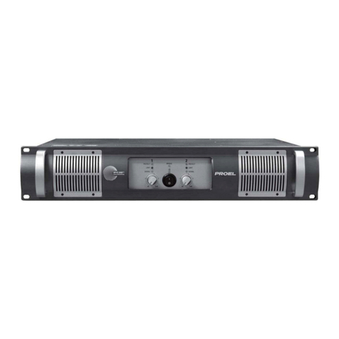
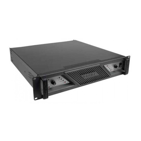
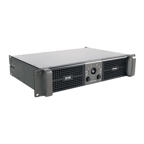
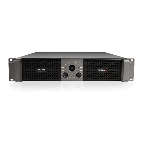
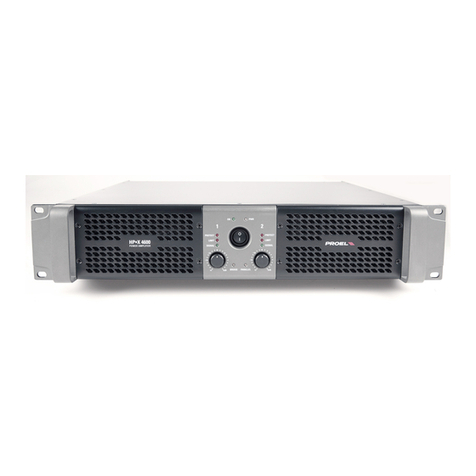
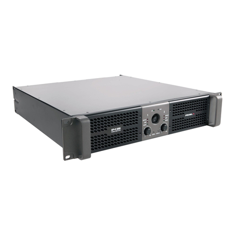
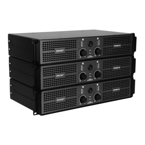
PROEL HP-X series User manual

1
ServiceManual
HPXSeries
ApplicableModels:
HPX900
HPX1200
HPX2400
HPX2800

2
TableofContents
1SafetyInstructions .................................................................................................................................................................. 3
2Technicalinformation ............................................................................................................................................................. 4
3BlockDiagram ......................................................................................................................................................................... 6
4SignalFlowchart...................................................................................................................................................................... 7
5HPX900MalfunctionAnalysisonPowerSupply ..................................................................................................................... 8
6HPX900MalfunctionAnalysisonAmplifiedPart .................................................................................................................... 10
7HPX1200/2400/2800MalfunctionAnalysisonAuxPowerSupplyBoard............................................................................... 12
8HPX1200/2400/2800MalfunctionAnalysisonDriving&ProtectionModuleCircuit............................................................. 13
9HPX1200MalfunctionAnalysisonSMPS ................................................................................................................................ 14
10HPX1200MalfunctionAnalysisonAmplifiedPart ................................................................................................................ 16
11HPX2400/2800MalfunctionAnalysisonSMPS..................................................................................................................... 18
12HPX2400/2800MalfunctionAnalysisonAmplifiedPart....................................................................................................... 20
13HPX900/1200/2400/2800InputBoard ................................................................................................................................. 22
14SpecialNotes......................................................................................................................................................................... 23

3
1SafetyInstructions:
1.1Duetohighvoltageinternal,pleasebecarefulduringtroubleshootingandmaintenancecourse.
Pleasereadtheusermanualandthismaintenancemanualfirst.
1.2Duetothewrongoperationincheckingandrepairingcoursewillresultstoruineddamageonsomeparts,sopleaseoperate
followthismanual.
1.3ThemaintenancepersonmustbeONLYaqualifiedprofessionalpersonnelauthorizedbyPROEL.
1.4Don’treplacethekeydevicesandadjusttheadjustablepotentiometersbyyourself,itwillchangetheparameterofthe
equipment.
1.5Pleasecutoffthepowertoguaranteethesafetyoftheservicepersonwhenrepairing.
1.6Thedevicesmarked inthedrawingindicatesakeydevice,pleasereplaceitONLYwithasparepartspecifiedby
PROEL.

4
TechnicalSpecification
MODEL HPX900 HPX1200 HPX2400 HPX2800
Power8ohm*200W 300W450W 600W
Power4ohm*300W 450W800W 1000W
Power2ohm** 450W 600W 1200W 1400W
PowerBRIDGE8ohm*400W 600W900W 1200W
PowerBRIDGE4ohm** 900W 1200W 2400W 2800W
OutputStage ClassAB ClassAB ClassHClassH
Frequencyresponse(+0/‐0.5d
B
20Hz‐20KHz 20Hz‐20KHz 20Hz‐20KHz 20Hz‐20KHz
InputSensitivity(nominal) +2.3dBu/1.0Vrms +1.0dBu/0.87Vrms +0.8dBu/0.85Vrms 0dBu/0.775Vrms
InputSensitivity(fixedgain) +8.3dBu/2.02Vrms +4.0dBu/1.23Vrms +5.8dBu/1.51Vrms +7.0dBu/1.73Vrms
GAIN(nominal/fixed) 32dB(40x)/26dB(20x) 35dB(56x)/32dB(40x) 37dB(71x)/32dB(40x) 39dB(89x)/32dB(40x)
InputConnectors XLRM,1/4"JACK,RCA XLRM,1/4"JACK,RCA XLRM,1/4"JACK,RCA XLRM,1/4"JACK,RCA
Impedance 20Kohm(balanced)
10Kohm(unbalanced)
20Kohm(balanced)
10Kohm(unbalanced)
20Kohm(balanced)
10Kohm(unbalanced)
20Kohm(balanced)
10Kohm(unbalanced)
OutputConnectors SPEAKONandBindingPost SPEAKONandBindingPost SPEAKONandBindingPost SPEAKONandBindingPost
DampingFactor >100 >100 >200 >200
SlewRate >20V/uS >20V/uS >20V/uS >20V/uS
S/NRatio(unweighted) >85dB >86dB >90dB >91dB
THD+N <0.1% <0.1% <0.1% <0.1%
Controls INPUTLEVEL,INPUTSENSITIVITY,
STEREO/BRIDGE/PARALLEL,
LOWPASSNOTCH(LPN),GND
INPUTLEVEL,INPUTSENSITIVITY,
STEREO/BRIDGE/PARALLEL,
LOWPASSNOTCH(LPN),GND
INPUTLEVEL,INPUTSENSITIVITY,
STEREO/BRIDGE/PARALLEL,
LOWPASSNOTCH(LPN),GND
INPUTLEVEL,INPUTSENSITIVITY,
STEREO/BRIDGE/PARALLEL,
LOWPASSNOTCH(LPN),GND
LEDIndicators POWER,ON,PARALLEL,
BRIDGE,
POWER,ON,PARALLEL,
BRIDGE,
POWER,ON,PARALLEL,
BRIDGE,
POWER,ON,PARALLEL,
BRIDGE,
Cooling VariablespeedDCfan VariablespeedDCfan VariablespeedDCfan VariablespeedDCfan
Protections AClowpower,DC,thermal,
shortcircuit,VHF,CLIPlimiter
AClowpower,DC,thermal,
shortcircuit,VHF,CLIPlimiter
AClowpower,DC,thermal,
shortcircuit,VHF,CLIPlimiter
AClowpower,DC,thermal,
shortcircuit,VHF,CLIPlimiter
MainsSupplyVoltage 230VAC(±10%)50/60Hzor
120VAC(±10%)50/60Hz
230VAC(±10%)50/60Hzor
120VAC(±10%)50/60Hz
230VAC(±10%)50/60Hzor
120VAC(±10%)50/60Hz
230VAC(±10%)50/60Hzor
120VAC(±10%)50/60Hz
MaximumConsumption 1450VA 1850VA 3550VA 4120VA
RatedConsumption*** 200VA 250VA 450VA 600VA
StandbyConsumption 50VA 65VA 65VA 65VA
Dimensions(WxHxD) 483x89x335mm
19"x3.5"x13.2"(2Urack)
483x89x395mm
19"x3.5"x15.6"(2Urack)
483x89x395mm
19"x3.5"x15.6"(2Urack)
483x89x395mm
19"x3.5"x15.6"(2Urack)
Weight 6Kg(13.2lb) 6.9Kg(15.2lb) 9.2Kg(20.3lb) 9.2Kg(20.3lb)
*RMSbothchannelTHD<1%
**40msburst
***Ratedconsumptionismeasuredwithpinknoisewithacrestfactorof12dB,thiscanbeconsideredastandardmusicprogram.

5
3BlockDiagram
3.1HPX900/HPX1200BlockDiagram:
VOL&DISPLA
Y
4
ACinput
1
ch1/ch2 input
3ch1/ch2 output
11
POWER
2
Protect-ch1
8Protect-ch2
9
Mode-ch1
6Mode-ch2
7
SMPSPOWER
5
TR
10
N
Prt
Limt
Clip
S+15V
GND-B
TEMP Prt
Limt
Clip
S+15V
GND-B
TEMP
TR
8-24V
F1
T4A
L
GND
GND
CH1output
CH2output
OUTPUT OUTPUT
+15V
-15V
gnd
ch1-input
ch2-input
+24V
GND-B
+24V
GND-B
+24V
GND-B
SIG SIG
+VCC
-VCC
-VCC +VCC
ch1vol
ch2 vol
prt
prt
clip
clip
sig
sig
parpllel
bripge
fan
passage
p
assa
g
e
passage
N
L
-VCC
+VCC

6
3.2HPX2400/HPX2800BlockDiagram:
VOL&DISPLAY
4
ACinput
1
Ch1/Ch2 input Ch1/Ch2 output
POWER
-
ON/OFF
2
Ch1-Protect Protect-ch2
9
Ch1-Mode Ch2-Mode
SMPSPOWER
5
N
Prt
Limt
Clip
GND-B
TR1
Clip
TR2
TR
8-24V
AC-FUSE
T12A/T15A
L
Ch1-GND
Ch1 output
Ch2-output
output output
+15V
-15V
gnd ch1-input
ch2-input
+24V
GND-B
+24V+24V
SIG SIG
+VCC
-VCC
-VCC+VCC
ch1vol
ch2 vol
prt
prt
clip
clip
sig
sig
parpllel
bripge
fan
N
L
-VCC+VCC
Ch2-GND
GND-B
+15V
-15V
gnd
Limt
Prt
GND-B
TR1
TR2
+15V
-15V
gnd
-VCC
fan
2KW-4.5KW

7
4SignalFlowchart
12
3
NON-INVERTED
I/P
XLR/F XLR/M
INVERTED
12
3
I/P
XLR/F XLR/M
INVERTED
OUTPUT
OUTPUT
OUTPUT STAGE
AMP FRONT END
ATTENUATOR
PREAMP
PREAMP
CHANNEL 1
CHANNEL 2
BRIDGE
PARALLEL
STEREO
MODE
SWITCH
ATTENUATOR
AMP FRONT END
OUTPUT STAGE
Protect
Circuit
BASS ENHANCED
OFF/ON
2 2
33
11
SENS
SWITCH
26dB/32dB

8
5HPX900MalfunctionAnalysisonPowerSupply
5.1CircuitDiagramofSMPS:
5.2MalfunctionAnalysisonSMPS:
Sequence
No.
Circuitto
check
MostProbablyFailures
1LineFilterand
theSoft‐start
‐TheACfuseontherearpanelwasburntwhenconnectedthe
electricity:checktheRT1varistordeviceandtheotherlinefilterdevice
toseeifthereisshortcircuit.
‐RL1Relaydoesnotpull‐inandthethermistorNPTR1isburntsothe
amplifiercannotstart.
‐Theoutput‐stagecircuitisburnt:thereforetheinputfusewas
destroyed.
‐Connectingthejumperof110VandACIport,thedoublevoltage
rectifierwillletthecircuitworkwith110Vand120Vmainsvoltage.
2Self‐excited
Circuit
‐TheamplifiercannotstartandtheInputfuseisburnt:mainlycheckif
thepowerswitchtransistorQ29~Q36isdamagedornot.Anyoneof
transistorsburntwillresulttonooutput;thencheckalsothezener
diodeDZ10,DZ11,DZ12,DZ13foropenorshortcircuit,itwillalso

9
resultstoblockingandhigh‐current.
3
On/Off
Anti‐shock
Circuit
‐Theamplifiercannotstartandthereisshocksoundwhenshutdown:
mainlycheckthedeviceofthiscircuit,seewhetherthedetached
photocouplerOP1/817,Q37,Q38isdamagedornot;
4FanSpeed
ControlCircuit
‐Fansdonotwork.
‐Fastrotating.
‐Itiseasilytogointoover‐heatprotectionifthefansdon’tspeedup
afterthemoduletemperatureincreasing.
5Rectifier
OutputCircuit
‐Powersupplyprotectionhappenedwhileswitchon.
‐Poweramplifierprotectionhappenedwhileswitchon.
‐Seriousdistortionofsound.
‐No±15Vvoltage.
‐No+24Voutput,resultstoalltheindicatorledonthepaneldonot
shine(start‐upunavailable)
RepairingGuide:
1)WhenrepairingtheSMPSboard,pleasecuttheDC/300Vfuse,seriesconnectone100W‐200Wlamp
tostartthemachine,preventingthedamageofrelateddevicewhenrepairing.
2)WhentheSMPScannotbestarted,repeatstheprotectionandrestart,pleasedisconnect+
VCC,‐VCCthentrytostart,ifitisnormal,itmeansshort‐circuitinamplifiedpart,checktheamplifier
circuit,otherwiseitisthefailureofSMPS.
3)Powersupplyprotectionmeans‐alltheindicatorlightsonthepanellitandthenimmediatelyblack
out.

10
6HPX900MalfunctionAnalysisonAmplifiedPart
6.1CircuitDiagramofAmplifier

11
6.2MalfunctionAnalysisonAmplifiedPart
Sequence
No.
CircuitFunctionFailure
1ClassABPower
Output
‐Powersupplyprotection:Anyoftheshortcircuitsofpoweroutput
transistor(CH1/Q2,Q3,Q10,Q11,CH2/Q19,Q20,Q24,Q25)willcause
thehighcurrentandpowersupplyprotection;
‐Amplifierprotection:+15V/‐15Visderivedfromthecurrentlimiting
ofR31,R40andD3,D4,ifthepowersupplyisabnormalitwillleadto
theDCoutput,amplifierwillgointoprotectstatus;
‐Cliplimitdoesn’twork–checkwhetherthedevicesofD7,D8,D9,
D40,LED1,R22isdamagedornot;
‐Amplifierself‐excitation–checkwhetherthedeviceofC3,C7,C8,
C10,C14wasturnbad.
‐Crossoverdistortion:checkwhethertheBEvoltageofthe
negative‐positivehalf‐wavepowertransistoris<0.2Vornot,thencheck
thevalueoftemperaturecompensationtransistorQandresistance
(R25,R26,R13)ischanged;
‐IC/5532damaged,unbalancedoftheofpositiveandnegativebias
voltage,hasDCoutputandpoweramplifiergoesintoprotection.
2
Overload/
Short‐circuit
Protection
‐Outputshort‐circuitandnoprotection,
‐Start–upprotection
3ClipLimit
Circuit
‐Nocliplimit,checkwhethertheD7ison;
‐Cliplimitdelayed,checktheD9andR19;
‐Waveformjitterwhenincliplimit;
‐Novolumegraduallyincreasefunctionafterstart‐up.
4
Over‐temperature
Protectionand
DelayCircuit
‐ThedelaycircuitprotectisacollectionofVHF,shortcircuit,
over‐temperature,DC‐protection,aswellasstart‐updelay.
‐WhentheProtectionfunctionandstart‐updelayisabnormalplease
checkthiscircuit.
5DCProtectCircuit
‐Nooutput‐relaydoesnotpull‐in,firstcheckwhetheritisnormalfor
24Vpowersupply,Q6baseisahighlevel.
‐On/offhasthesoundofshock‐alongpull‐inontherelay;
RepairingGuide:
1)Whenrepairingtheamplifier,pleaseseriesconnecta100W—200Wlamptostarttheequipmentin
ordertoavoidthedamageofrelateddevice;
2)ThecircuitofCH1andCH2isthesamebutthesequenceNo.ofdeviceisdifferent,allthetesting
parametercanbeshared;
3)Poweramplifierprotectionmeansthepowersupplyandprotectionindicatoronthepanelarelit;

12
7HPX1200/2400/2800MalfunctionAnalysisonAuxPower
SupplyBoard
7.1HPX1200/2400/2800CircuitDiagramofAuxpowersupplyModule
7.2MalfunctionAnalysisonAuxpowersupply
Sequence
No.
Circuit
Function
Failure
1AuxPower
SupplyBoard
‐STYLEDisoff;theequipmentisunavailabletostart.
‐Checkthecircuit,seeiftheCN1pinandthecopperfoilofAuxPower
Supplyisbroken;
‐Whenamplifierconnectstopowersupply,theAuxPowerSupply
(self‐activatedswitch)willstarttowork,providetwogroupstandby
powersupply+5V&+16V.Amongthem,CN3/+5Visforpoweron/off
led(orange),CN1+16Visforthemainpowercontrolboard,themain
poweron/offiscontrolledbytheCN4inplug.WhentheCN4isclosed,
OP3/817willbeconnected,Q2/8050willbedownedtolowlevel(VPI).
RepairingGuide:
Whenrepairingthepowerboard,pleasecuttheDC/300Vfuse,seriesconnecta100W—200Wlampto
startthemachine,preventingthedamageofrelateddevicewhenrepairing.

13
8HPX1200/2400/2800MalfunctionAnalysisonSMPSCONTROL
Circuit
8.1CircuitDiagramofSMPSCONTROL
8.2MalfunctionAnalysisonSMPSCONTROLModuleCircuit
Sequence
No.
Circuit
Function
Failure
1SMPSControl
‐Theequipmentisunavailabletostart;
‐Protectionfunctionwillbeactivatedwheninlowimpedanceoutput;
‐Cyclicprotectionoftheswitchpower;
‐Delaystart,over‐voltagePROT,low‐voltagePROTandovercurrent
PROT.
RepairingGuide:
1)Whenrepairingthecontrolboard,youcancuteveryprotectcircuitgraduallyfoundthedefective
area!

14
9HPX1200MalfunctionAnalysisonSMPS.
9.1CircuitDiagramofSMPS
9.2HPX1200MalfunctionAnalysisonSMPS:
Sequence
No.
Circuit
Function
Failure
1LineFilterand
theSoft‐start
‐TheACfuseontherearpanelwasburntwhenconnectedthe
electricity:checktheRT1varistordeviceandtheotherlinefilter
devicetoseeifthereisshortcircuit.
‐RL1Relaydoesnotpull‐inandthethermistorNPTR1isburntsothe
amplifiercannotstart.
‐Connectingthejumperof110VandACIport,thedoublevoltage
rectifierwillletthecircuitworkwith110Vand120Vmainsvoltage.
2LLCresonant
converter
‐85°ctemperaturecontrolswitchisoftenclosedresulttothe
start‐upunavailable;
‐Ifstart‐uptheequipment,high‐currentwillresultstotheburntout
oftheDC/300Vfuse;
3
FanSpeed
Control
Circuit
‐Fansdonotwork.
‐Fastrotating.
‐Itiseasilytogointoover‐heatprotectionifthefansdon’tspeed
upafterthemoduletemperatureincreasing.
4Rectifier
Output
‐Powerprotectioncausedbythedamageofhigh‐speeddiodes
(D13,D14,D15,D16,E11,E12,C27,C261,C271)oranyofrectifier
filterdevice.
‐Poweramplifierstart‐upprotection.
‐Poweramplifierprotectioncausedbyno±15Voutput;allthe
indicatoronthepaneldonotshinedbecauseno+24Voutput
(start‐upunavailable)
RepairingGuide:
1)WhenrepairingtheSMPSboard,pleasecuttheDC/300Vfuse,seriesconnecta100W—200W
lamptostartthemachine,preventingthedamageofrelateddevicewhenrepairing.
2)WhentheSMPScannotbestarted,repeatstheprotectionandrestart,pleasedisconnect+

15
VCC,‐VCCthentrytostart,ifitisnormal,itmeansshort‐circuitinamplifiedpart,checkthe
amplifiedcircuit,otherwiseitisthefailureofSMPS;
3)Powersupplyprotectionmeans–alltheindicatorlightsonthepanellitandthenimmediately
blackout;

16
10HPX1200MalfunctionAnalysisonAmplifiedPart
10.1CircuitDiagramofAmplifier

17
10.2MalfunctionAnalysisonAmplifiedPart
Sequence
No.
CircuitFunctionFailure
1ClassABPower
Output
‐Powersupplyprotection:Breakdownofanyonepowertransistor
willcauseashortcircuitandresultstohighcurrentprotection.
‐Amplifierprotection:+15V/‐15Vifthepowersupplyisabnormalwill
leadtotheDCoutput,amplifierwillgointoprotectionstatus;
‐Nocliplimit;
‐Amplifierself‐excitated;
‐Cross‐overdistortion;
‐IC/5532damaged,unbalancedoftheofpositiveandnegativebias
voltage,hasDCoutputandpoweramplifiergoesintoprotection.
2
Overload/
Short‐circuit
Protection
‐Outputshort‐circuitandnoprotection,
‐Start–upprotection;
3ClipLimitCircuit
‐Nocliplimit;
‐Cliplimitdelayed;waveformjitterwhenincliplimit;
‐Volumewillnotgomaximumgraduallyafterstart‐up.
4
VHF/Over‐heat
Protectionand
DelayCircuit
‐TheprotectiondelaycircuitisacollectionofVHF,shortcircuit,
over‐heat,DC‐protection,aswellasstart‐updelay.
WhentheProtectionfunctionandstart‐updelayisabnormalplease
checkthiscircuit.
5DCProtection
‐Nooutput‐relaydoesnotpull‐in,firstcheckwhetheritisnormalfor
24Vpowersupply,Q6baseisahighlevel.
‐On/offhasthesoundofshock‐alongpull‐inontherelay;
RepairingGuide:
1)Whenrepairingtheamplifier,pleaseseriesconnecta100W—200Wlamptostarttheequipmentto
avoidthedamageofrelateddevice.
2)ThecircuitofCH1andCH2isthesamebutthesequenceNo.ofdeviceisdifferent,allthetesting
parametercanbeshared;
3)Poweramplifierprotectionmeansthepowerandprotectionindicatorsonthefrontpanelarelit;

18
11HPX2400/2800MalfunctionAnalysisonSMPS
11.1CircuitDiagramofSMPS

19
11.2MalfunctionAnalysisonSMPS:
Sequence
No.
CircuitFunctionFailure
1
Line
Filter/Soft‐start/
Rectification
‐TheACfuseoftherearpanelisburntwhenconnectedthe
electricity‐checktheRT1deviceandlinefilterdevicetoseeifthereis
shortcircuit.
‐Thereissmokebutitcanstillworkwhileoutputpower,check
whetherthethermistor/NPTR1wasburntcausedbytherelaydidn’t
pull‐in;
‐Connectthejumperof110VandACIport,thedoublevoltage
rectifierwillletthecircuitworkin110Vand120Vstatus;
2LLCResonant
Converter
‐85°Cthermalswitchisoftenclosedresulttothestart‐up
unavailable;
‐Whilestart‐uptheequipment,high‐currentwillresultstotheburnt
outoftheprimaryDC/DC/300Vfuse;
‐Switchingtransistorisnotworking,checkthedrivingtransformer
T2,aloopisformedbytheprimarycurrentgothroughthe
transformerT1A,resonantinductorL4andresonantcapacitorC106;
3FanSpeed
ControlCircuit
‐Fansdonotwork.
‐Fastrotating.
‐Itiseasilytogointoover‐heatprotectionifthefansdon’tspeedup
afterthemoduletemperatureincreasing.
4RectifierOutput
‐Powerprotectioncausedbythedamageofhigh‐speeddiodesD49,
D50,D51,D52,D67,D68,D73,D74,E4,E5,E7,E8,C6,C7,C8,C9,or
anyofrectifierfilterdevice.
‐Poweramplifierstart‐upprotection.
‐Outputdistortionandpowerprotectioncausedbyno±15Voutput;
‐Alltheindicatorsonthepaneldonotshinedbecauseno+24V
output(start‐upunavailable).
RepairingGuide:
1)Whenrepairingthepowerboard,pleasecuttheDC/300Vfuse,seriesconnecta100W—200W
lamptostartthemachine,preventingthedamageofrelateddevicewhenrepairing.
2)WhentheSMPScannotbestarted,repeatstheprotectionandrestart,pleasedisconnect+VCC,
‐VCCthentrytostart,ifitisnormal,itmeansshort‐circuitinamplifiedpart,checktheamplified
circuit,otherwiseitisthefailureofSMPS;
3)Powersupplyprotectionmeans‐alltheindicatorsonthefrontpanellitandthenimmediately
blackout;

20
12HPX2400/2800MalfunctionAnalysisonAmplifiedPart
12.1CircuitDiagramofAmplifier
Other manuals for HP-X series
3
This manual suits for next models
4
Table of contents
Other PROEL Amplifier manuals

PROEL
PROEL ACDT180V User manual

PROEL
PROEL DPX1200PFC User manual

PROEL
PROEL PSA 240 User manual

PROEL
PROEL DPX1000 User manual

PROEL
PROEL AUP160D User manual

PROEL
PROEL PSW2600 User manual

PROEL
PROEL acdt120 User manual

PROEL
PROEL ACDT180 User manual

PROEL
PROEL AMIX63 User manual

PROEL
PROEL AUP4125S User manual

PROEL
PROEL AMP240V4 User manual

PROEL
PROEL HP-X series User manual

PROEL
PROEL HP-X series User manual

PROEL
PROEL AMP03 User manual

PROEL
PROEL PREW User manual

PROEL
PROEL HPD2004 User manual

PROEL
PROEL ACDT90 User manual

PROEL
PROEL AUP120 User manual

PROEL
PROEL PMA 120 User manual

PROEL
PROEL HPD2004 User manual