PROEL SW118H User manual

USER’S MANUAL
MANUALE UTENTE
www.proel.com
SW118H
SUBWOOFER
USER'S MANUAL
MANUALE UTENTE
BENUTZERHANDBUCH
MANUEL DE L'UTILISATEUR
MANUAL DEL USUARIO

FCC COMPLIANCE NOTICE
This device complies with part 15 of the FCC rules. Operation is subject to the following two
conditions:
(1) This device may not cause harmful interference, and
(2) this device must accept any interference received, including interference that may cause
undesired operation.
CAUTION: Changes or modifications not expressly approved by the party responsible for
compliance could void the user’s authority to operate the equipment.
NOTE: This equipment has been tested and found to comply with the limits for a Class B digital
device, pursuant to part 15 of the FCC Rules. These limits are designed to provide reasonable
protection against harmful interference in a residential installation. This equipment generates,
uses, and can radiate radio frequency energy and, if not installed and used in accordance
with the instruction manual, may cause harmful interference to radio communications.
However, there is no guarantee that interference will not occur in a particular installation. If
this equipment does cause harmful interference to radio or television reception, which can
be determined by turning the equipment off and on, the user is encouraged to try to correct
the interference by one or more of the following measures:
• Reorient or relocate the receiving antenna.
• Increase the separation between the equipment and receiver.
• Connect the equipment into an outlet on a circuit different from that to which the receiver
is connected.
• Consult the dealer or an experienced radio/TV technician for help.
This marking shown on the product or its literature, indicates that it should not be disposed with other household wastes at the end of its
working life. To prevent possible harm to the enviroment or human health from uncontrolled waste disposal, please separate this from other
types of wastes and recycle it responsibly to promote the sustainable reuse of material resources. Household users should contact either
the retailer where they purchased this product, or their local government office, for details of where and how they can take this item for
environmentally safe recycling. Business users should contact their supplier and check the terms and conditions of the purchase contract.
This product should not be mixed with other commercial wastes for disposal.
The lightning flash with arrowhead symbol within an equilateral triangle is intended to alert the user to the presence of uninsulated “dangerous
voltage” within the product’s enclosure, that may be of sufficient magnitude to constitute a risk of electric shock to persons.
The exclamation point within an equilateral triangle is intended to alert the user to the presence of important operating and maintenance
(servicing) instructions in the literature accompanying the appliance.
The information contained in this publication has been carefully prepared and checked. However no responsibility will be taken for any errors. All
rights are reserved and this document cannot be copied, photocopied or reproduced in part or completely without written consent being obtained
in advance from PROEL. PROEL reserves the right to make any aesthetic, functional or design modification to any of its products without any prior
notice. PROEL assumes no responsibility for the use or application of the products or circuits described herein.
Il marchio riportato sul prodotto o sulla documentazione indica che il prodotto non deve essere smaltito con altri rifiuti domestici al termine
del ciclo di vita. Per evitare eventuali danni all’ambiente si invita l’utente a separare questo prodotto da altri tipi di rifiuti e di riciclarlo in
maniera responsabile per favorire il riutilizzo sostenibile delle risorse materiali. Gli utenti domestici sono invitati a contattare il rivenditore
presso il quale è stato acquistato il prodotto o l’ufficio locale preposto per tutte le informazioni relative alla raccolta differenziata e al
riciclaggio per questo tipo di prodotto. Gli utenti aziendali sono invitati a contattare il proprio fornitore e verificare i termini e le condizioni
del contratto di acquisto. Questo prodotto non deve essere smaltito unitamente ad altri rifiuti commerciali.
Il simbolo del lampo con freccia in un triangolo equilatero intende avvertire l'utilizzatore per la presenza di "tensioni pericolose" non isolate
all'interno dell'involucro del prodotto, che possono avere una intensità sufficiente a costituire rischio di scossa elettrica alle persone.
Il punto esclamativo in un triangolo equilatero intende avvertire l'utilizzatore per la presenza di importanti istruzioni per l'utilizzo e la
manutenzione nella documentazione che accompagna il prodotto.
Le informazioni contenute in questo documento sono state attentamente redatte e controllate. Tuttavia non è assunta alcuna responsabilità per
eventuali inesattezze. Tutti i diritti sono riservati e questo documento non può essere copiato, fotocopiato, riprodotto per intero o in parte senza previo
consenso scritto della PROEL. PROEL si riserva il diritto di apportare senza preavviso cambiamenti e modifiche estetiche, funzionali o di design a
ciascun proprio prodotto. PROEL non assume alcuna responsabilità sull’uso o sul l’applicazione dei prodotti o dei circuiti qui descritti.

Das Kennzeichen auf dem Gerät oder den beiliegenden Unterlagen zeigt an, dass das Gerät am Ende seiner Lebensdauer nicht im Hausmüll entsorgt werden darf. Aus
Umweltschutzgründen bitten wir den Anwender, das Gerät von anderem Müll getrennt zu entsorgen und dem Recycling zuzuführen, damit die Rohstoffe umweltverträglich
wiederverwertet werden können. Private Anwender wenden sich dazu bitte an den Händler, bei dem sie das Produkt gekauft haben, oder an eine örtliche Behörde, die
für Informationen zur Mülltrennung und zum Recycling dieser Art von Geräten geben kann. Gewerbliche Anwender werden gebeten, sich an den Zulieferer zu wenden
und die Vertragsbedingungen des Kaufvertrags zu überprüfen. Das Gerät darf nicht zusammen mit anderem Gewerbemüll entsorgt werden.
Das Symbol mit einem Pfeilblitz in einem gleichseitigen Dreieck warnt den Anwender vor „gefährlicher Spannung“ ohne Isolierung im Gehäuse des Geräts. Diese kann hoch
genug sein, um Stromschlaggefahr zu verursachen.
Das Ausrufezeichen in einem gleichseitigen Dreieck weist den Anwender auf wichtige Anweisungen zum Gebrauch und zur Instandhaltung des Geräts in den beiligenden
Unterlagen hin.
Die Angaben in diesem Dokument wurden sorgfältig zusammengestellt und kontrolliert. Für mögliche Ungenauigkeiten übernehmen wir dennoch keine Haftung. Alle Rechte
vorbehalten. Das Dokument darf ohne vorherige schriftliche Genehmigung von PROEL nicht ganz oder in Teilen kopiert oder reproduziert werden. PROEL behält sich das Recht vor,
ohne Vorankündigung Änderungen an der Gestaltung, an den Funktionen oder am Design aller ihrer Produkte vorzunehmen. PROEL haftet nicht für den Gebrauch oder die Verwendung
der hier beschriebenen Geräte oder elektrischen Systeme.
La marque reportée sur le produit ou sur la documentation indique que l'appareil ne doit pas être éliminé avec d'autres déchets domestiques au
terme du cycle de sa vie. Afin d'éviter tout dommage à l'environnement, l'utilisateur est invité à séparer cet appareil des autres types de déchets et
de le recycler de manière responsable pour favoriser la réutilisation durable des ressources matérielles. Les utilisateurs domestiques sont invités
à contacter le revendeur où l'appareil a été acheté ou le service local préposé afin d'obtenir toutes les informations relatives au tri sélectif et au
recyclage pour ce type de produit. Les utilisateurs des entreprises sont invités à contacter leur fournisseur et à vérifier les termes et les conditions
du contrat d'achat. Cet appareil ne doit pas être éliminé avec d'autres déchets commerciaux.
Le symbole d'un éclair avec une flèche dans un triangle équilatéral est destiné à avertir l'utilisateur de la présence de «tensions dangereuses» non
isolées dans le boîtier de l'appareil, lesquelles peuvent avoir une intensité suffisante pour constituer un risque de choc électrique pour les personnes.
Le point d'exclamation dans un triangle équilatéral est destiné à avertir l'utilisateur de la présence d'instructions importantes en vue de l'utilisation et
de la maintenance de l'appareil dans la documentation qui l'accompagne.
Les informations contenues dans ce document ont été rédigées avec attention et contrôlées. Toutefois, la société PROEL n'assume aucune responsabilité
en cas d'inexactitude. Tous les droits sont réservés et ce document ne peut être copié, photocopié, reproduit en entier ou en partie, sans avoir obtenu au
préalable le consentement écrit de la société PROEL. PROEL se réserve le droit d'apporter, sans préavis, des changements et des modifications esthétiques,
fonctionnelles ou de design à tous ses produits. PROEL n'assume aucune responsabilité quant à l'utilisation ou l'application des appareils ou des circuits
décrits dans cette notice.
La marca reproducida en el producto o en la documentación indica que el producto no se debe eliminar con otros desechos domésticos al final de su
ciclo de vida útil. Para evitar posibles daños al medio ambiente se invita al usuario a separar este producto de otros tipos de desechos y reciclarlo de
forma responsable para favorecer el uso sostenible de los recursos materiales. Los usuarios domésticos deben ponerse en contacto con el revendedor
donde han comprado el producto o la oficina local encargada, para conocer todas las informaciones correspondientes a la recogida selectiva y al
reciclaje para este tipo de producto. Se invita a las empresas a ponerse en contacto con su proveedor y controlar los términos y las condiciones del
contrato de compra. Este producto no se debe eliminar junto con otros desechos comerciales.
El símbolo del relámpago con flecha en un triángulo equilátero tiene la intención de advertir al usuario respecto a la presencia de "tensiones peligrosas"
no aisladas dentro de la envoltura del producto, que pueden tener una intensidad suficiente para constituir riesgo de descarga eléctrica a las personas.
El punto exclamativo en un triángulo equilátero tiene la intención de advertir al usuario respecto a la presencia de importantes instrucciones para el uso
y el mantenimiento en la documentación que acompaña el producto.
Las informaciones contenidas en este documento se han redactado y controlado atentamente. Sin embargo, el fabricante se exime de toda responsabilidad
por posibles inexactitudes. Todos los derechos reservados; por tanto este documento no se puede copiar, fotocopiar, reproducir total o parcialmente sin la
autorización previa escrita por parte de PROEL. PROEL si reserva el derecho de realizar sin previo aviso cambios estéticos, funcionales o de diseño a cualquier
producto suyo. PROEL no se asume ninguna responsabilidad por el uso o la aplicación de los productos o de los circuitos que se describen aquí.
PROELPROEL
PROEL

4Index
INDEX
TECHNICALSPECIFICATIONS............................ 4
FREQUENCYRESPONSE ................................ 4
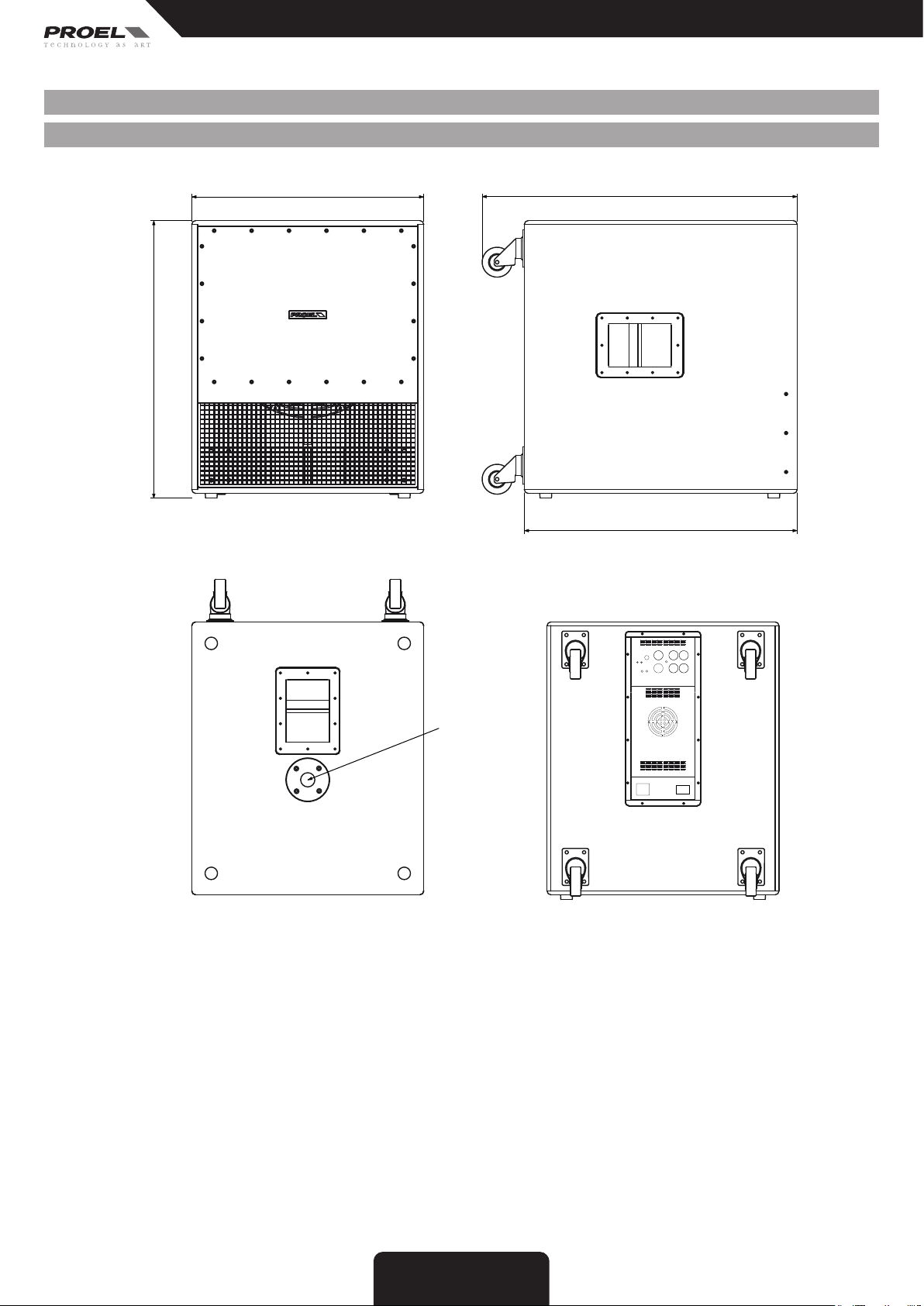
DIMENSIONS ......................................... 5
ACCESSORIES......................................... 5
PASSIVE - CONTROL PANEL (FIG. 1) ...................... 6
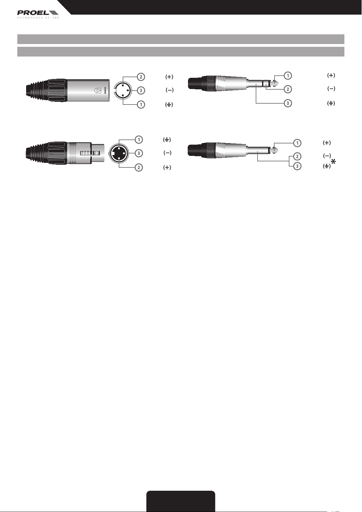
PASSIVE - CONNECTIONS (FIG. 2) ........................ 6
PASSIVE -CONFIGURATION EXAMPLES (FIG. 3) ............ 6
ACTIVE - CONTROL PANEL (FIG. 4) ....................... 7
ACTIVE - CONNECTIONS (FIG. 5) ......................... 7
ACTIVE - CONFIGURATION EXAMPLES (FIG. 6) ............. 8
SAFETYANDPRECAUTIONS ............................ 9
INCASEOFFAULT..................................... 9
TROUBLESHOOTING ................................... 9
CECONFORMITY...................................... 10
PACKAGING, SHIPPING AND COMPLAINT . . . . . . . . . . . . . . . 10
WARRANTY AND PRODUCTS RETURN . . . . . . . . . . . . . . . . . . . 10
INSTALLATION AND DISCLAIMER. . . . . . . . . . . . . . . . . . . . . . . 10
POWER SUPPLY AND MAINTENANCE . . . . . . . . . . . . . . . . . . . 10
GENERALINFORMATION .............................. 11
SW118HP - PASSIVE VERSION INSTRUCTIONS ( FIG. 1 / 2 / 3)11
SW118HA - ACTIVE VERSION INSTRUCTIONS ( FIG. 4 / 5 / 6) 12
INHALT
TECHNISCHEDATEN...................................... 5
FREQUENZGANG ......................................... 5
ABMESSUNGEN.......................................... 6
ZUBEHÖR................................................ 7
PASSIV - REGLER (ABB. 1) ................................. 8
PASSIV - ANSCHLÜSSE (ABB. 2) ............................ 8
PASSIV - KONFIGURATIONSBEISPIELE (ABB. 3)............... 8
AKTIV - REGLER (ABB. 4)................................... 9
AKTIV - ANSCHLÜSSE (ABB. 5) ............................ 10
AKTIV - KONFIGURATIONSBEISPIELE (ABB. 6) ............... 11
SICHERHEITSHINWEISE.................................. 22
BEIEINEMDEFEKT....................................... 22
HÄUFIG AUFTRETENDE PROBLEME ........................ 22
EG-KONFORMITÄT ....................................... 23
VERPACKUNG, TRANSPORT UND REKLAMATIONEN.......... 23
GARANTIE UND RÜCKGABE............................... 23
INSTALLATION UND VERWENDUNGSEINSCHRÄNKUNGEN.... 23
STROMVERSORGUNG UND INSTANDHALTUNG .............. 23
ALLGEMEINEINFORMATIONEN............................ 24
SW118HP - ANLEITUNGEN PASSIVE VERSION ( ABB. 1 / 2 / 3 ) . 24
SW118HA - ANWEISUNGEN AKTIVE VERSION (ABB. 4 / 5 / 6) . . 25
ÍNDICE
CARACTERÍSTICASTÉCNICAS..............................5
RESPUESTAENFRECUENCIA...............................5
DIMENSIONES ...........................................6
ACCESORIOS.............................................7
PASIVAS - PANEL DE CONTROL (FIG. 1) ......................8
PASIVA - CONEXIONES (FIG. 2) .............................8
PASIVA - EJEMPLOS CONFIGURACIONES (FIG. 3) .............8
ACTIVA - PANEL DE CONTROL (FIG. 4) .......................9
ACTIVA - CONEXIONES (FIG. 5) ............................10
ACTIVA - EJEMPLOS CONFIGURACIONES (FIG. 6) ............11
ADVERTENCIAS PARA LA SEGURIDAD......................32
EN CASO DE AVERÍA .....................................32
PROBLEMAS COMUNES ..................................32
CONFORMIDADCE.......................................33
EMBALAJE, TRANSPORTE Y RECLAMACIONES ..............33
GARANTÍAS Y DEVOLUCIONES ............................33
INSTALACIÓN Y LIMITACIONES DE USO ....................33
ALIMENTACIÓN Y MANTENIMIENTO .......................33
INFORMACIÓNGENERAL.................................34
SW118HP - INSTRUCCIONES VERSIÓN PASIVA (FIG. 1 / 2 / 3) . .34
SW118HA - INSTRUCCIONES VERSIÓN ACTIVA (FIG. 4 / 5 / 6) . .35
INDICE
SPECIFICHETECNICHE................................. 4
RISPOSTAINFREQUENZA .............................. 4
DIMENSIONI.......................................... 5
ACCESSORI........................................... 5
PASSIVE - PANNELLO DI CONTROLLO (FIG. 1).............. 6
PASSIVA - CONNESSIONI (FIG. 2) ........................ 6
PASSIVA - ESEMPI CONFIGURAZIONI (FIG. 3).............. 6
ATTIVA - PANNELLO DI CONTROLLO (FIG. 4) ............... 7
ATTIVA - CONNESSIONI (FIG. 5).......................... 7
ATTIVA - ESEMPI CONFIGURAZIONI (FIG. 6) ............... 8
AVVERTENZE PER LA SICUREZZA ....................... 14
INCASODIGUASTO.................................. 14
PROBLEMATICHECOMUNI............................. 14
CONFORMITÀCE ..................................... 15
IMBALLAGGIO, TRASPORTO E RECLAMI . . . . . . . . . . . . . . . . . 15
GARANZIEERESI..................................... 15
INSTALLAZIONE E LIMITAZIONI D’USO . . . . . . . . . . . . . . . . . . 15
ALIMENTAZIONE E MANUTENZIONE . . . . . . . . . . . . . . . . . . . . 15
INFORMAZIONIGENERALI............................. 16
SW118HP - ISTRUZIONI VERSIONE PASSIVA ( FIG. 1 / 2 / 3 ) 16
SW118HA - ISTRUZIONI VERSIONE ATTIVA (FIG. 4 / 5 / 6) . . . 17
INDEX
SPÉCIFICATIONS TECHNIQUES . . . . . . . . . . . . . . . . . . . . . . . . . . 5
RÉPONSE EN FRÉQUENCE. . . . . . . . . . . . . . . . . . . . . . . . . . . . . . . 5
DIMENSIONS ......................................... 6
ACCESSOIRES......................................... 7
PASSIVE - PANNEAU DE COMMANDE (FIG. 1) ............. 8
PASSIVE - CONNEXIONS (FIG. 2) ......................... 8
PASSIVE - EXEMPLES DE CONFIGURATIONS (FIG. 3)........ 8
ACTIVE - PANNEAU DE COMMANDE (FIG. 4)............... 9
ACTIVE - CONNEXIONS (FIG. 5) ......................... 10
ACTIVE - EXEMPLES DE CONFIGURATIONS (FIG. 6) ........ 11
MISESENGARDEDESÉCURITÉ ........................ 27
ENCASDEPANNE.................................... 27
PROBLÈMESCOMMUNS............................... 27
CONFORMITÉCE...................................... 28
EMBALLAGE, TRANSPORT ET RÉCLAMATIONS . . . . . . . . . . . 28
GARANTIESETRETOURS.............................. 28
INSTALLATION ET LIMITES D'UTILISATION. . . . . . . . . . . . . . . 28
ALIMENTATION ET MAINTENANCE . . . . . . . . . . . . . . . . . . . . . 28
INFORMATIONSGÉNÉRALES........................... 29
SW118HP - INSTRUCTIONS VERSION PASSIVE ( FIG. 1 / 2 / 3 ) .
29
SW118HA - INSTRUCTIONS VERSION ACTIVE (FIG. 4 / 5 / 6). 30
4
5
5
6
7
8
8
8
9
01
11
37
37
37
38 CE
38
38
38
38
39
39 SW118HP
40SW118HA

5
Specifications
MODEL SW118HP SW118HA
System type Bandpass enclosure subwoofer Bandpass enclosure subwoofer
Nominal Impedance 8 ohm -
Power Handling (continuos) 1000 W -
Power Handling (peak) 2000 W -
Frequency Response (-10dB) 34 Hz - 170 Hz (without lter) 34 Hz - 140 Hz
LP Crossover Frequency suggested between 80 - 125 Hz switchable 80 Hz / 125 Hz
Sensitivity 98 dBspl @ 1 W/1 m -
Loudspeaker 18'' woofer - 4" VC 18'' woofer - 4" VC
Amplifier Continuous Power -1000 W Class D
Max SPL 131 dBspl 131 dBspl
Connectors 2 x NEUTRIK SPEAKON (IN/LINK) IN: 2 x NEUTRIK COMBO
OUT: 2 x NEUTRIK XLR-M
LINK: 2 x NEUTRIK XLR-M
Controls -Level, GND lift
Filter Frequency, Phase
Input Impedance - 30 kohm balanced
15 kohm unbalanced
Input Sensitivity - 0 dBu / 0.775 V
Angular coverage omnidirectional omnidirectional
Construction 18 mm plywood 18 mm plywood
Finishing Anti-scratch BLACK paint nish Anti-scratch BLACK paint nish
Mounting Pole 1 1
Transport 3 x steel handles
4 x 75 mm wheels 3 x steel handles
4 x 75 mm wheels
Weight 45 kg (100 lb) 48.5 kg (107 lb)
Dimensions (W x H x D) 595 x 713 x 810 mm 595 x 713 x 810 mm
Power Supply - 240-230 VAC or 120 VAC - 50/60 Hz
see label on the apparatus
Maximun Consumption - 1450 VA
Rated Consumption* - 420 VA
* Rated consumption is measured with pink noise with a crest factor of 12 dB, this can be considered a standard music program.
SW118HASW118HP
2k
1k
500200
100
50
2020 2kHz
dB
0
-10
-20
-30
80 Hz FILTER 125 Hz FILTER
2k
1k
500200
100
50
2020 2kHz
dB
100
90
80
70
UNFILTERED
TECHNICAL SPECIFICATIONS TECHNISCHE DATEN
SPECIFICHE TECNICHE
SPÉCIFICATIONS TECHNIQUES
CARACTERÍSTICAS TÉCNICAS
FREQUENCY RESPONSE FREQUENZGANG
RISPOSTA IN FREQUENZA
RÉPONSE EN FRÉQUENCE
RESPUESTA EN FRECUENCIA

6Dimensions
71.3 cm
28.1"
59.5 cm
23.4"
80.8 cm
31.8"
Mounting Pole
70.0 cm
27.6"
NOTE: This product is designed to work on floor and is not equipped with rigging flying points, do not suspend the loudspeakers from the handle.
NOTA: Questo prodotto è progettato per funzionare sul pavimento e non sono previsti punti di sospensione, non sospendere l'altoparlante dalle
maniglie.
HINWEIS: Dieses Produkt wurde entwickelt, um auf den Boden aufgestellt zu werden. Es sind keine Aufhängepunkte vorgesehen. Lautsprecher
nicht an den Griffen aufhängen.
REMARQUE: ce produit, conçu pour fonctionner au sol, ne possède pas de points de suspension. Ne pas suspendre le haut-parleur par les poignées.
NOTA: Este producto está diseñado para funcionar en el suelo y no cuenta con puntos de suspensión; no suspenda el altavoz por las asas.
DIMENSIONS ABMESSUNGEN
DIMENSIONI
DIMENSIONS
DIMENSIONES

7
accessories
ACCESSORIES
KP210
SPEAKER STAND ‑ SUBWOOFER / SPEAKER ALUMINIUM BLACK FINISH
ZUBEHÖR
KP210
AUTSPRECHERSTÄNDER ‑ SUBWOOFER / ALUMINIUMLAUTSPRECHER
SCHWARZ
ACCESORIOS
KP210
SOPORTE ALTAVOCES ‑ SUBWOOFER / ALTAVOZ DE ALUMINIO DE ACABADO
NEGRO
ACCESSORI
KP210
SUPPORTO ALTOPARLANTI ‑ SUBWOOFER / ALTOPARLANTE ALLUMINIO
FINITURA NERO
ACCESSOIRES
KP210
SUPPORT HAUT‑PARLEURS ‑ SUBWOOFER / HAUT‑PARLEUR FINITION COLORIS
NOIR
KP210
SUBWOOFER

8FIG. 1 / 2 / 3
2-
1+
2+
1-
20mm
0.8"
8mm
0.3"
RED
BLACK
PROEL suggested
equipment:
max 2000W (4 Ω) power amplifier
(HP-D 3400PFC: 1700W 4 Ω x2 )
suggested equipment:
Digital or Analog loudspeaker processor
suggested equipment:
HP-D 2000 ( mode: 2x 1000W bridge )
LEFT
Flash or Net full range speaker
RIGHT
Flash or Net full range speaker
LEFT
SW118HP subwoofer speaker
RIGHT
SW118HP subwoofer speaker
SW118HP (8 ohm)
to other 2x SW118HP
SW118HP (8 ohm)
sub ARRAY
SUB+SAT system
LOW HIGH
R
L
R
2
L
1
PASSIVE - CONTROL PANEL (FIG. 1)
PASSIVE - CONNECTIONS (FIG. 2)
PASSIVE -CONFIGURATION EXAMPLES (FIG. 3)
PASSIV - REGLER (ABB. 1)
PASSIV - ANSCHLÜSSE (ABB. 2)
PASSIV - KONFIGURATIONSBEISPIELE (ABB. 3)
PASSIVE - PANNELLO DI CONTROLLO (FIG. 1)
PASSIVA - CONNESSIONI (FIG. 2)
PASSIVA - ESEMPI CONFIGURAZIONI (FIG. 3)
PASSIVE - PANNEAU DE COMMANDE (FIG. 1)
PASSIVE - CONNEXIONS (FIG. 2)
PASSIVE - EXEMPLES DE CONFIGURATIONS (FIG. 3)
)1
)2
)3
PASIVAS - PANEL DE CONTROL (FIG. 1)
PASIVA - CONEXIONES (FIG. 2)
PASIVA - EJEMPLOS CONFIGURACIONES (FIG. 3)

9
FIG. 4 / 5
ACTIVE - CONTROL PANEL (FIG. 4)
AKTIV - REGLER (ABB. 4)
ATTIVA - PANNELLO DI CONTROLLO (FIG. 4)
ACTIVE - PANNEAU DE COMMANDE (FIG. 4)
)4
ACTIVA - PANEL DE CONTROL (FIG. 4)

10
INPUT (ingresso)
Jack (bilanciato)
INPUT
Jack (balanced)
sleeve - ground
tip - hot
ring - cold
INPUT (ingresso)
XLR bilanciato maschio
INPUT
Balanced male XLR
POWER OUTPUT - uscite altoparlanti
Connettore per cavo tipo Speakon Neutrik NL4
PROEL code - NL4FX
Codice PROEL - NL4FX
PROEL code - NL4FX
Codice PROEL - NL4FX
SPEAKER POWER OUTPUTS
Neutrik NL4 Speakon Cable Connector
ground
hot
cold
INPUT (ingresso)
Jack (sbilanciato)
INPUT
Jack (unbalanced)
ground
tip - hot
cold
*nota: connettere insieme cold e ground
per cavi da bilanciato a sbilanciato
*note: connect both cold and ground
to make cable from balanced to unbalanced
2-
1+
2+
1-
20mm
0.8"
8mm
0.3"
RED
BLACK
positive / red / rosso
n.c. 1+
negative / black / nero
1-
n.c.
POWER OUTPUT - uscite altoparlanti
Connettore per cavo tipo Speakon Neutrik NL4
SPEAKER POWER OUTPUTS
Neutrik NL4 Speakon Cable Connector
2-
1+
2+
1-
channel 1 positive
canale 1 positivo
1+
channel 1 negative
canale 1 negativo
1-
OUTPUT 1
2-
1+
2+
1-
bridge positive
n.c. 1+
bridge negative
1-
n.c.
OUTPUT BRIDGE
2-
1+
2+
1-
20mm
0.8"
8mm
0.3"
RED
BLACK
channel 2 positive
n.c. 1+
channel 2 negative
1-
n.c.
OUTPUT 2
uscita 1 uscita BRIDGE uscita 2
channel 2 negative
canale 2 negativo
NOTE: channels 3 and 4 are equal to channel 1 and 2 respectively.
NOTA: canali 3 e 4 sono equivalenti ai canali 1 e 2 rispettivamente.
2+
channel 2 positive
canale 2 positivo
2-
LINK (uscita)
XLR bilanciato femmina
LINK (output)
Balanced female XLR
ground
hot
cold
ACTIVE - CONNECTIONS (FIG. 5)
AKTIV - ANSCHLÜSSE (ABB. 5)
ATTIVA - CONNESSIONI (FIG. 5)
ACTIVE - CONNEXIONS (FIG. 5)
)5
ACTIVA - CONEXIONES (FIG. 5)
INPUT
Balanced male XLR
INPUT (ingresso)
XLR bilanciato maschio
INPUT (Eingang)
XLR symmetrisch, männlich
INPUT (entrée)
XLR symétrique mâle INPUT
(entrada)
XLR balanceado macho
INPUT
LINK (output)
Balanced female XLR
LINK (uscita)
XLR bilanciato femmina
LINK (Ausgang)
XLR symmetrisch, weiblich
LINK (sore)
XLR symétrique femelle
LINK (salida)
XLR balanceado hembra
LINK ()
XLR
INPUT
Jack (balanced)
INPUT (ingresso)
Jack (bilanciato)
INPUT (Eingang)
Klinkenstecker (symmetrisch)
INPUT (entrée)
Jack (symétrique)
INPUT (entrada)
Jack (balanceado)
INPUT)
INPUT
Jack (unbalanced)
INPUT (ingresso)
Jack (sbilanciato)
INPUT (Eingang)
Klinkenstecker (unsymmetrisch)
INPUT (entrée)
Jack (asymétrique)
INPUT (entrada)
Jack (debalanceado)
INPUT)
*note: connect both cold and ground to make cable from balanced to unbalanced
*nota: conneere insieme cold e ground per cavi da bilanciato a sbilanciato
*Hinweis: bei Verbindung von symmetrisch zu unsymmetrisch Kalt und Masse zusammen anschließen
*remarque : connecter ensemble cold et ground pour des câbles de symétrique à asymétrique
*nota: conecte juntos cold y ground para cables de balanceado a desbalanceado

PROEL suggested
equipment:
Mseries mixer
Subwoofer output of
analog or digital
loudspeaker processor
RIGHT
FLASH15HA (sat) +
SW118HA (sub)
LEFT
FLASH15HA (sat) +
SW118HA (sub)
LEFT
FLASH12HA
RIGHT
FLASH12HA
basic stereo system
1x SW118HA
+
2x FLASH12HA
1000W + 500W x2
= 2000W
standard stereo system
2x SW118HA
+
2x FLASH15HA
1000W x2 + 600W x2
= 3200W
subwoofer reinforcement
PHASE must be the
same for all subs
LA FASE deve essere
la stessa per tutti i sub
set the PHASE switch
to obtain the louder bass level
impostare l’interruttore della FASE
per ottenere il maggior livello di bassi
typical switch
setting for this configuration
impostazione tipica degli
interruttori per questa configurazione
RIGHT
NET215A (sat) +
SW118HA (sub)
LEFT
NET215A (sat) +
SW118HA (sub)
hi-power stereo system
2x SW118HA
+
2x NET215A
1000W x2 + 1000W x2
= 4000W
typical switch
setting for this configuration
impostazione tipica degli
interruttori per questa configurazione
L
“WARNING”TO REDUCE THE RISK OF FIRE OR ELECTRIC SHOCK
DONOT EXPOSE THIS PRODUCT TO RAIN OR MOISTURE
AC~ POWER
ON SIGN
LIMIT
LINE INLINK
LEVEL
CAUTION!
RISKOF ELECTRIC SHOCK
DONOT OPEN
“WARNING”TO REDUCE THE RISK OF FIRE OR ELECTRIC SHOCK
DONOT EXPOSE THIS PRODUCT TO RAIN OR MOISTURE
AC~ POWER
ON SIGN
LIMIT
LINE INLINK
LEVEL
CAUTION!
RISKOF ELECTRIC SHOCK
DONOT OPEN
L
R
L
R
L
R
ACTIVE - CONFIGURATION EXAMPLES (FIG. 6)
AKTIV - KONFIGURATIONSBEISPIELE (ABB. 6)
ATTIVA - ESEMPI CONFIGURAZIONI (FIG. 6)
ACTIVE - EXEMPLES DE CONFIGURATIONS (FIG. 6)
)6
ACTIVA - EJEMPLOS CONFIGURACIONES (FIG. 6)
PHASE must be the same for all subs
LA FASE deve essere la stessa per tutti i sub
DIE PHASE muss für alle Sub dieselbe sein
LA PHASE doit être identique pour tous les subs
LA FASE debe ser la misma para todos los sub
sub
set the PHASE switch to obtain the louder bass level
impostare l’interruttore della FASE per ottenere il
maggior livello di bassi
PHASEN-Schalter einstellen, um den höchsten Pegel
der Bässe zu erlangen
congurer l'interrupteur de la PHASE an d'obtenir
le plus grand niveau de basses
congure el interruptor de la FASE para obtener el
mayor nivel de bajos
tipical switch setting for this conguration
impostazione tipica degli interruttori per
questa congurazione
Typische Schaltereinstellung für diese
tipical switch setting for this conguration
impostazione tipica degli interruttori per
questa congurazione
Typische Schaltereinstellung für diese
Konguration
conguration typique des interrupteurs pour cette conguration
conguración típica de los interruptores para esta conguración
Konguration
conguration typique des interrupteurs pour cette conguration
conguración típica de los interruptores para esta conguración
11
FIG. 6

12 English
SAFETY AND PRECAUTIONS
• CAUTION: Before using this product read carefully the following safety instructions. Take a look of this manual entirely and preserve it for future
reference.
When using any electric product, basic precautions should always be taken, including the following:
– To reduce the risk, close supervision is necessary when the product is used near children.
– Protect the apparatus from atmospheric agents and keep it away from water, rain and high humidity places.
– This product should be site away from heat sources such as radiators, lamps and any other device that generate heat.
– This product should be located so that its location or position does not interfere with its proper ventilation and heating dissipation.
– Care should be taken so that objects and liquids do not go inside the product.
– The product should be connected to a power supply mains line only of the type described on the operating instructions or as marked on the
product. Connect the apparatus to a power supply using only power cord included making always sure it is in good conditions.
– WARNING: The mains plug is used as disconnect device, the disconnect device shall remain readily operable.
– Do not cancel the safety feature assured by means of a polarized line plug (one blade wider than the other) or with a earth connection.
– Make sure that power supply mains line has a proper earth connection.
– Power supply cord should be unplugged from the outlet during strong thunderstorm or when left unused for a long period of time.
– Do not place objects on the product’s power cord or place it in a position where anyone could trip over, walk on or roll anything over it. Do not
allow the product to rest on or to be installed over power cords of any type. Improper installations of this type create the possibility of fire hazard
and/or personal injury.
– This product may be capable of producing sound levels that could cause
permanent hearing loss. Exposure to extremely high noise levels may cause
permanent hearing loss. Individuals vary considerably in susceptibility to noise-
induced hearing loss, but nearly everyone will lose some hearing if exposed to
sufficiently intense noise for a period of time. The U.S. Government’s Occupational
Safety and Health Administration (OSHA) has specified the permissible noise
level exposures shown in the following chart. According to OSHA, any exposure
in excess of these permissible limits could result in some hearing loss. To ensure
against potentially dangerous exposure to high sound pressure levels, it is
recommended that all persons exposed to equipment capable of producing high
sound pressure levels use hearing protectors while the equipment is in operation.
Ear plugs or protectors in the ear canals or over the ears must be worn when
operating the equipment in order to prevent permanent hearing loss if exposure
is in excess of the limits set forth here. Keep your's attention that childrens and
pets are more suscetible to excessive noise levels.
IN CASE OF FAULT
• In case of fault or maintenance this product should be inspected only by qualied service personnel when:
– There is a flaw either in the connections or in the supplied connecting cables.
– Liquids have spilled inside the product.
– The product has fallen and been damaged.
– The product does not appear to operate normally or exhibits a marked change in performance.
– The product has been losted liquids or gases or the enclosure is damaged.
• Do not operate on the product, it has no user-serviceable parts inside, refer servicing to an authorized maintenance centre.
TROUBLESHOOTING
No Power
(active) • The loudspeaker's "POWER" switch is off.
• Make sure the mains AC outlet is live (check with a tester or a lamp).
• Make sure the mains plug is securely plugged into mains AC outlet.
No Sound
(active) • Is the input LEVEL control for the channel turned up?
• Is the SIGNAL LED illuminated? If not check if your signal level is too low or check the signal cable, mixer and other
equipment setting and cabling.
• Are you sure your signal cables works properly? check it using a cable tester or replacing with a new one.
No Sound
(passive) • Is the loudspeaker cable connected?
• Is the SPEAKON cable connector correctly inserted? turn it clockwise until it clicks.
• Are you sure your power cable works properly? check it using a cable tester or replacing with a new one.
• Are you sure your power cables connected properly? you have to connect the amplier to the suboowofer input and your
full range loudspeakers to HIGH PASS output.
A lack of bass
(active) • With two or more subwoofer working, check the polarity switch of all subwoofers: all these switches must be in the same
position.
Distorted Sound • Input signal level is too high. Turn down your level controls.
NOTE: The loudspeakers should never be operated at a level which causes the amplifier Clip LEDs to illuminate constantly.
Different channel
level • Check if are using a balanced cable for one channel and an unbalanced one for the other, as this would cause a
considerable difference in channel levels.
• Be sure that your loudspeaker system is fully connected and both loudspeakers have the same impedance.
Noise / Hum • Enable GND LIFT button on rear panel, if the problem persist press all GND LIFT buttons for all system's ampliers.
• Whenever possible, preferably use only balanced cables. Unbalanced lines may also be used but may result in noise over
long cable runs.
• Sometimes it helps to plug all audio equipment into the same AC circuit so they share a common ground.
Duration Per Day
In Hours
Sound Level dBA
Slow Response
Typical
Example
8 90 Duo in small club
6 92
4 95 Subway Train
397
2 100 Very loud classical music
1.5 102
1 105 Traffic noise
0.5 110
0.25 or less 115 Loudest parts at a rock concert

13
English
CE CONFORMITY
• Proel products comply with directive 89/336/EEC (EMC) and following modications 92/31/EEC and 93/68/EEC, as stated in EN 55103-1 and EN
55103-2 standards and with directive 73/23/EEC (LVD) and following modications 93/68/EEC, as stated in EN 60065 standard.
• Under the EM disturbance, the ratio of signal-noise will be changed above 10dB.
PACKAGING, SHIPPING AND COMPLAINT
• This unit package has been submitted to ISTA 1A integrity tests. We suggest you control the unit conditions immediately after unpacking it.
• If any damage is found, immediately advise the dealer. Keep all unit packaging parts to allow inspection.
• Proel is not responsible for any damage that occurs during shipment.
• Products are sold “delivered ex warehouse” and shipment is at charge and risk of the buyer.
• Possible damages to unit should be immediately notied to forwarder. Each complaint for manumitted package should be done within eight days
from product receipt.
WARRANTY AND PRODUCTS RETURN
• Proel products have operating warranty and comply their specications, as stated by manufacturer.
• Proel warrants all materials, workmanship and proper operation of this product for a period of two years from the original date of purchase. If
any defects are found in the materials or workmanship or if the product fails to function properly during the applicable warranty period, the owner
should inform about these defects the dealer or the distributor, providing receipt or invoice of date of purchase and defect detailed description.
This warranty does not extend to damage resulting from improper installation, misuse, neglect or abuse. Proel S.p.A. will verify damage on returned
units, and when the unit has been properly used and warranty is still valid, then the unit will be replaced or repaired. Proel S.p.A. is not responsible
for any "direct damage" or "indirect damage" caused by product defectiveness.
INSTALLATION AND DISCLAIMER
• Proel products have been expressly designed for audio application, with signals in audio range (20Hz to 20kHz). Proel S.p.A. declines any liability
for damages to objects or persons caused by lacks of maintenance, modifications, improper use, installation not applying safety instructions and
precautions and not performed at the state of the art.
• The installation of these speakers is provided for indoors, in case of use outdoors be sure that the speakers are installed correctly in a safe
location protected from wind, rain and umidity. To avoid performance deterioration of mechanical, acoustics and electrical parts is not advisable
to leave these speakers exposed outdoors for a long period of time, so we suggest a temporary installation for the limited sound events.
• The installation of these speakers is provided for oor or by means of specic stands able to support their weight. Therefore avoid installation on
unstable elements such as: furnitures, chairs and vibrant surfaces as stages or other speakers without appropriate x point specically designed
to avoid speaker movement. Then avoid the use of inadequate supports, we suggest to use PROEL stands and accessories only.
• In case of the speakers are provided of rigging points: DO NOT SUSPEND THE SPEAKERS FROM THE HANDLES, use exclusively these rigging
points. Consult professional rigger or structural engineers prior to suspending loudspeakers from a structure not intended for that use. Always know
the
working load limit of the structure supporting the loudspeakers. Always make sure that the rigging hardware minimum rating is at least five times
the actual load, speakers and rigging hardware.
• In case of suspended installations of active loudspeakers where is not possible to turn on and off the speakers from their appropriate switches,
we recomend to install switches on the mains lines, for this purpose consult an expert electrician for the exact dimensioning of wiring.
• Locate the speakers as far away as possible from radio or television receivers or other sensitive equipment. These speakers have a strong
magnetic field which can induce hum and noise into unshielded devices that are located nearby with consequent deterioration of reception of image
and sound.
• Proel S.p.A. reserves the right to change these specications at any time without notice.
POWER SUPPLY AND MAINTENANCE
• Clean only with dry cloth.
• Check periodically that the slots for its proper ventilation and heating dissipation are not obstructed by dust, remove the dust using a dry brush
or a compressed air gun.
• The amplied loudspeakers of Proel have been designed with CLASS I construction and must be connected always to a mains socket outlet with
a proctetive earth connection (the third grounding prong).
• Before connecting the product to the mains outlet make certain that the mains line voltage matches that shown on the rear of the product, a
tolerance of up to ±10% is acceptable.
• Inside the amplied loudspeakers are present special safety devices such as:
ü Fuse on rear panel.
ü Amplier over-heating protection.
ü Protection against excessive power applied at each speaker.
• THE REPLACEMENT OF FUSES INSIDE THE APPARATUS MUST BE MADE ONLY BY QUALIFIED PERSONNEL.
• CHECK THE CONDITION OF THE PROTECTION FUSE, ACCESSIBLE OUTWARD, ONLY WITH THE APPARATUS SWITCHED OFF AND
DISCONNECTED FROM THE MAINS LINE OUTLET.
• REPLACE THE PROTECTION FUSE ONLY WITH SAME TYPE AS SHOWN ON THE PRODUCT.
• IF AFTER THE SUBSTITUTION, THE FUSE INTERRUPTS AGAIN THE APPARATUS WORKING, DO NOT TRY AGAIN THEN CONTACT THE PROEL
SERVICE CENTER.

14 English
GENERAL INFORMATION
Thank you for having chosen a PROEL product. The SW Series is a range of subwoofers designed by Proel to complement
full-range speakers, including the NET and FLASH Series.
Thanks to the variety of size, power and SPL, the SW sub-woofers can offer the perfect low extension solution for any
full-range speaker.
All the SW models feature large voice coil (VC) woofers and a band-pass design, providing very ‘punchy’ and dynamic lows
together with an extended low frequency response. The SW118H model combine advanced technical characteristics with
state-of-the-art 18" Celestion ferrite speaker. The active version uses a class D amplier module that can generate up to
1000W of continuous power in a compact and reliable package, it include a stereo preamp section, 24dB/oct. crossover
filters with selectable frequency and phase reverse switch.
The cabinets are built with 18mm plywood and feature 3 metal handles and sturdy 75mm wheels for an easy transport.
SW118HP - PASSIVE VERSION INSTRUCTIONS ( FIG. 1 / 2 / 3)
1. INPUT (SPEAKON)
External amplier power input: this is the connector where you plug in the power cable coming from your power amplier
or powered mixer. The powered signal is NOT ltered by an internal passive crossover, so for a better coupling with
external satellite speakers we suggest the use of an amplier with a 100Hz low pass lter built-in, or the use of an external
analog or digital loudspeaker processor, see the examples section for futher details.
The frequency transition suggested must be in the range of 80-120 Hz. The INPUT speakon has this pin connection:
PIN1+: positive power signal (usually red wire)
PIN1-: negative power signal (usually black wire)
2. LINK (SPEAKON)
Output of the power signal to be sent to another loudspeaker. The connector has the same pin out as specified above.
CHOOSE THE AMPLIFIER POWER
We give you two power-handling numbers: RMS (continuous), and PEAK. So these data suggest you can use any amplier
with a power capability equal or less the power-handling, but this rule is valid only if the amplier never clip anytime.
Preventing loudspeaker damage caused by clipping, that is likely the number one cause of damage, and assuming you
want to use the full capability of the loudspeaker, we recommend the use of an amplier with a built-in limiter to prevent
clipping, in this case the rated power capability must be the same continuous power rating of the loudspeaker into the
same specified impedance (tipically 4 or 8 ohms):
• To obtain the best result using a single SW118HP (with an impedance of 8 ohm), we suggest the use of PROEL HPD-1000
in bridge configuration,
• To obtain the best result using two SW118HP (with an impedance of 8 ohm each), we suggest the use of PROEL HPD-2000
amplifier for a standard stereo configuration.
• To obtain the best result using two SW118HP connected in parallel (with a resulting impedance of 4 ohm), we suggest
the use of an amplier capable to delivery 2000W at maximum with 4 ohm load.
IMPORTANT: Clipping occurs when the signal at the output of any device in the system (not just the amplifier) reaches its
maximum level. Proper operation of a sound system includes being aware of the types of audio signals being reproduced,
controlling the output levels accordingly, and operating all the devices in the system so that no clipping occurs within
the signal chain.

15
SW118HA - ACTIVE VERSION INSTRUCTIONS ( FIG. 4 / 5 / 6)
1. INPUT LEFT (combo XLR-JACK input)
This is a female combo connector, which accepts a XLR or a JACK plug from almost any type of equipment with a balanced
or unbalanced line level outputs. The XLR input is wired as follows:
Pin 1 = shield or ground
Pin 2 = + positive or "hot"
Pin 3 = - negative or "cold"
The JACK input is wired as follows:
Tip = + positive or "hot"
Ring = - negative or "cold"
Sleeve = shield or ground
When connecting an unbalanced signal, wire them as follows:
Pin2 / Tip = + positive or "hot"
Pin 1-3 / Sleeve = shield or ground
NOTE: Whenever possible, use always balanced cables. Unbalanced lines may also be used but may result in noise
over long cable runs. In any case, avoid using a balanced cable for one channel and an unbalanced one for the other.
2. LINK LEFT (XLR output balanced)
This is a male XLR connector, it is connected in parallel with the respective line input, so the LINK is wired as the input.
Connect these to the inputs of other powered speakers to make an array.
3. OUT LEFT (XLR output balanced)
This is a male XLR connector, it provides a balanced line-level signal. This signal is ltered with an high-pass lter to
connect a sat speaker. This output is wired as follows:
Pin 1 = shield or ground
Pin 2 = + positive or "hot"
Pin 3 = - negative or "cold"
4. INPUT RIGHT (combo XLR-JACK input)
Same as above. Use both inputs and outputs when connect a stereo system to a single subwoofer (1 sub + 2 sat). In the
case of mono system (1 sub + 1 sat for each channel) you can use left or right input without distinction.
5. LINK RIGHT (XLR output balanced)
This is a male XLR connector, it is connected in parallel with the respective line input, so the LINK is wired as the input.
Connect these to the inputs of other powered speakers to make an array.
6. OUT RIGHT (XLR output balanced)
Same as above. Use both inputs and outputs when connect a stereo sytem to a single subwoofer (1 sub + 2 sat). In the
case of mono system (1 sub + 1 sat for each channel) you have to use the same channel used for input: left or right.
7. GND LIFT switch
This switch lift the ground of the balanced audio inputs from the earth-ground of the amplier. If you have HUM noise
problem on one or more loudspeaker try to change the position of these switches (often all up or all down for all the
amplifiers in the system). Please note that to have an effect all cables must be balanced.
8. FILTER 80 / 125 Hz switch
Use this switch to set the crossover frequency at 80 Hz or 125 Hz for the internal filter and for the OUT LEFT and RIGHT
connectors. Choose the crossover frequency by your taste or music genre.
9. LEVEL control
Rotary level control: it attenuates the level of the signal sent to the subwoofer speaker. The attenuation ranges from “0”
fully closed (the signal is completely attenuated) to “10” fully open, nominal level (the signal is not attenuated in any way,
so is fed to the internal amplifier at the same level at which it arrives on input).
10. SIGN/CLIP indicator
GREEN LED illuminates to indicate the presence of the signal at the built-in amplier input.
RED LED illuminates when the internal amplifier's output is limited. When this LED flashes reduce the input signal level.
11. PHASE 0° / 180° switch
This switch reverses the polarity of the subwoofer. Depending on the placement of the subwoofer relative to the full-range
sat speakers, you can get a better low-frequency response in the room if you reverse the polarity of the subwoofer’s signal.
Listen in different positions of the venue in order to try which is the best sounding setting.
English

16
NOTE: ALL SUBWOOFER SPEAKERS MUST BE HAVE THE SAME POLARITY, if you note a lack in lowest frequency range
using more than one subwoofer, probably you have a subwoofer inverted respect the other. Be always sure all these
switches are in same position.
12. ON indicator
GREEN LED: when lighted indicates amplifier has been turned on and AC power is available.
13. POWER switch
Speaker is "ON" when the switch is in the "I" position, use this switch to set the speaker power to ON or OFF.
NOTE: When you shut down your equipment, turn off the speaker first.When powering up, turn on the speaker last.
14. AC~ socket
Here’s where you plug in your speaker’s mains supply cord. You should always use the mains cord supplied with the
speaker. Be sure your speaker is turned off before you plug the mains supply cord into an electrical outlet.
15. FUSE holder
Here is placed the mains protection fuse.
Please follow the instructions on page 10 of this manual to replace it.
16. Cooling vent
Air cooling vent: always keep it clear of dust, cables or other objects.
English

17
Italiano
AVVERTENZE PER LA SICUREZZA
• ATTENZIONE: Durante le fasi di uso o manutenzione, devono essere prese alcune precauzioni onde evitare danneggiamenti alle strutture
meccaniche ed elettroniche del prodotto.
Prima di utilizzare il prodotto, si prega di leggere attentamente le seguenti istruzioni per la sicurezza. Prendere visione del manuale d’uso e
conservarlo per successive consultazioni:
– In presenza di bambini, controllare che il prodotto non rappresenti un pericolo.
– Posizionare l’apparecchio al riparo dagli agenti atmosferici e a distanza di sicurezza dall’acqua, dalla pioggia e dai luoghi ad alto grado di umidità.
– Collocare o posizionare il prodotto lontano da fonti di calore quali radiatori, griglie di riscaldamento e ogni altro dispositivo che produca calore.
– Collocare o posizionare il prodotto in modo che non ci siano ostruzioni alla sua propria ventilazione e dissipazione di calore.
– Evitare che qualsiasi oggetto o sostanza liquida entri all’interno del prodotto.
– Il prodotto deve essere connesso esclusivamente alla rete elettrica delle caratteristiche descritte nel manuale d’uso o scritte sul prodotto, usando
esclusivamente il cavo rete in dotazione e controllando sempre che sia in buono stato, in particolare la spina e il punto in cui il cavo esce dal prodotto.
– ATTENZIONE: Se il cavo rete viene scollegato dall'apparecchio per spegnerlo, il cavo rete rimarrà operativo in quanto la sua spina è ancora
collegata alla rete elettrica.
– Non annullare la sicurezza garantita dall'uso di spine polarizzate o con messa a terra.
– Fare attenzione che il punto di alimentazione della rete elettrica sia dotato di una efficiente presa di terra.
– Disconnettere il prodotto dalla rete elettrica durante forti temporali o se non viene usato per un lungo periodo di tempo.
– Non disporre oggetti sul cavo di alimentazione, non disporre i cavi di alimentazione e segnale in modo che qualcuno possa incianparci. Altresì
non disporre l’apparecchio sui cavi di altri apparati. Installazioni inappropriate di questo tipo possono creare la possibilità di rischio di incendio e/o
danni alle persone.
– Questo prodotto può essere capace di produrre livelli sonori che possono
causare perdite d’udito permanenti. Si raccomanda di evitare l’esposizione
ad alti livelli sonori o livelli non confortevoli per lunghi periodi di tempo.
Se si notano perdite d’udito o acufeni (fischi) consultare un audiologo. La
sensibilità alla perdita di udito causata da eccessiva esposizione al rumore
varia considerevolmente da individuo a individuo, ma mediamente ciascuno può
accusare perdita di udito se esposto al rumore per un certo periodo di tempo.
Come suggerimento viene riportata la tabella dei tempi massimi di esposizione
giornaliera al rumore al fine di evitare perdite di udito, fonte della tabella è l'ente
per la salute degli Stati Uniti (OSHA).
Si fà presente inoltre che sia i bambini che gli animali domestici sono più sensibili
al rumore intenso.
IN CASO DI GUASTO
• In caso di guasto o manutenzione questo prodotto deve essere ispezionato da
personale qualificato quando:
– Ci sono difetti sulle connessioni o sui cavi di collegamento in dotazione.
– Sostanze liquide sono penetrate all’interno del prodotto.
– Il prodotto è caduto e si è danneggiato.
– Il prodotto non funziona normalmente esibendo una marcato cambio di prestazioni.
– Il prodotto perde sostanze liquide o gassose o ha l’involucro danneggiato.
• Non intervenire sul prodotto. Rivolgersi a un centro di assistenza autorizzato Proel.
PROBLEMATICHE COMUNI
Assenza di
alimentazione
(attiva)
• L'interruttore dell'altoparlante è spento.
• Accertarsi che ci sia effettivamente tensione sulla presa di corrente (controllare con un tester o una lampada).
• Accertarsi che la spina di rete sia saldamente inserita nella presa.
Nessun
Suono
(attiva)
• Il controllo di livello LINE IN è girato al massimo?
• Il LED di segnale è acceso? Se non lo è, controllate se il livello di segnale sia troppo basso o controllate il cavo di segnale, le
impostazioni e i cablaggi di mixer o altri apparecchi collegati.
• Sei sicuro che il cavo di segnale sia in buono stato? controlla il cavo con un tester oppure sostituiscilo con un altro.
Nessun
Suono
(passiva)
• Il cavo degli altoparlanti è collegato?
• Il connettore SPEAKON del cavo altoparlanti è correttamente inserito? girarlo nchè non si sente il click.
• Sei sicuro che il cavo di potenza sia in buono stato? controlla il cavo con un tester oppure sostituiscilo con un'altro.
• Sei sicuro che i cavi di potenza siano connessi correttamente? controlla di aver collefato l'amplicatore all'ingresso del
subwoofer e l'usita HIGH PASS al diffusore satellite.
Mancanza di
bassi
(attiva)
• Con due o più subwoofer funzionanti, controllare l'interruttore della polarità su tutti i subwoofer: tutti questi interruttori
devono essere nella medesima posizione.
Suono
Distorto • Il livello del segnale di ingresso è troppo alto, abbassare i controlli del livello.
NOTA: L'altoparlante non deve mai lavorare con livelli che fanno illuminare in modo pressochè costante il LED rosso
dell'amplificatore.
Livello
differente sui
canali
• Controllare se si stanno usando cavi bilanciati su un canale e sbilanciati sull'altro, ciò può comportare una notevole
differenza di livello sui canali.
• Assicurarsi che gli altoparlanti siano completamente collegati e abbiano la medesima impedenza.
Ore di esposizione
giornaliera
Livello sonoro in
dBA
costante di tempo
SLOW
Esempio
Tipico
8 90 Duo acustico in un piccolo club
6 92
4 95 Treno metropolitano
397
2 100 Musica classica molto forte
1.5 102
1 105 Rumore da traffico urbano intenso
0.5 110
0.25 or less 115 Parte più rumorosa di un concerto rock

18 Italiano
Rumore /
Ronzio • Abilitare l'interruttore GND LIFT sul pannello posteriore, se il problema persiste premere i GND LIFT su tutti gli amplicatori
del sistema.
• Qualora possibile, usare preferibilmente solo cavi bilanciati. Cavi sbilanciati possono essere usati ma risultano rumorosi su
lunghe distanze.
• Talvolta può essere di aiuto alimentare tutto l'equipaggiamento audio collegandolo dalla stessa linea di corrente AC, in
modo che tutti gli apparati condividano la stessa presa di terra.
CONFORMITÀ CE
• I Prodotti Proel sono conformi alla direttiva 89/336/EEC (EMC) e successive modiche 92/31/EEC e 93/68/EEC, secondo gli standard EN 55103-1 ed
EN 55103-2 ed alla direttiva 73/23/EEC (LVD) e successive modiche 93/68/EEC, secondo lo standard EN 60065.
• Se sottoposto a disturbi EM, il rapporto segnale-rumore può essere superiore a 10dB.
IMBALLAGGIO, TRASPORTO E RECLAMI
• L’imballo è stato sottoposto a test di integrità secondo la procedura ISTA 1A. Controllare il prodotto subito dopo l’apertura dell’imballo.
• Se vengono riscontrati danni informare immediatamente il rivenditore. Conservare quindi l’imballo completo per permetterne l’ispezione.
• Proel declina ogni responsabilità per danni causati dal trasporto.
• Le merci sono vendute “franco nostra sede” e viaggiano sempre a rischio e pericolo del distributore.
• Eventuali avarie e danni dovranno essere contestati al vettore. Ogni reclamo per imballi manomessi dovrà essere inoltrato entro 8 giorni dal
ricevimento.
GARANZIE E RESI
• I Prodotti Proel sono provvisti della garanzia di funzionamento e di conformità alle proprie speciche, come dichiarate dal costruttore.
• La garanzia di funzionamento è di 24 mesi dopo la data di acquisto. I difetti rilevati entro il periodo di garanzia sui prodotti venduti, attribuibili a
materiali difettosi o difetti di costruzione, devono essere tempestivamente segnalati al proprio rivenditore o distributore, allegando evidenza scritta
della data di acquisto e descrizione del tipo di difetto riscontrato. Sono esclusi dalla garanzia difetti causati da uso improprio o manomissione. Proel
SpA constata tramite verica sui resi la difettosità dichiarata, correlata all’appropriato utilizzo, e l’effettiva validità della garanzia; provvede quindi
alla sostituzione o riparazione dei prodotti, declinando tuttavia ogni obbligo di risarcimento per danni diretti o indiretti eventualmente derivanti dalla
difettosità.
INSTALLAZIONE E LIMITAZIONI D’USO
• I Prodotti Proel sono destinati esclusivamente ad un utilizzo specico di tipo sonoro: segnali di ingresso di tipo audio (20Hz-20kHz). Proel declina
ogni responsabilità per danni a terzi causati da mancata manutenzione, manomissioni, uso improprio o installazione non eseguita secondo le norme
di sicurezza e a regola d'arte.
• L'installazione di questi altoparlanti è prevista per uso interno, in caso di utilizzo all'esterno assicurarsi che gli altoparlanti siano installati
correttamente in un luogo sicuro e protetto dal vento, pioggia e umidità. Al fine di non deteriorarne le prestazioni meccaniche, acustiche ed elettriche
non è consigliato lasciare questi altoparlanti esposti all'aperto per lunghi periodi di tempo, si consiglia pertanto una installazione temporanea
all'evento da sonorizzare.
• L'installazione di questi altoparlanti è prevista a pavimento o tramite specici supporti adeguati al peso da sostenere. Pertanto evitare
l'installazione su elementi instabili quali: mobili, sedie e superfici vibranti quali palchi e altri altoparlanti non dotati di fissaggi atti a evitare spostamenti
dell'altoparlante. Quindi evitare di utilizzare supporti non adeguati, si consiglia di usare solo i supporti suggeriti da PROEL.
• Qualora gli altoparlanti siano muniti di punti di ssaggio per la sospensione: NON SOSPENDERE GLI ALTOPARLANTI DALLE MANIGLIE usare
esclusivamente questi punti di fissaggio. Consultare attrezzisti professionisti o ingegneri strutturali prima di sospendere altoparlanti da strutture non
intese per questo specifico scopo. Non superare il limite di carico della struttura che sosterrà gli altoparlanti. Assicurarsi che tutte le meccaniche
di sostegno siano in grado di sopportare un peso almeno 5 volte superiore al carico degli altoparlanti incluse le meccaniche di sospensione.
• Nel caso di installazioni sospese di altoparlanti attivi in cui non sia possibile l'uso dei singoli interruttori degli altoparlanti per l'accensione e lo
spegnimento dei medesimi, si raccomanda l'installazione di interruttori sulle linee di alimentazione della rete elettrica, a tale proposito consultare
un esperto elettricista per il corretto dimensionamento dell'impianto elettrico.
• Installare questi altoparlanti il più lontano possibile da radioricevitori e televisori. Un altoparlante installato in prossimità di questi apparati può
causare interferenza e rumore con conseguente degrado della ricezione di immagini e suoni.
• La Proel S.p.a. si riserva di modicare il prodotto e le sue speciche senza preavviso.
ALIMENTAZIONE E MANUTENZIONE
• Pulire il prodotto unicamente con un panno asciutto.
• Controllare periodicamente che le aperture di raffredamento non siano ostruite da accumuli di polvere, provvedere alla rimozione della polvere
mediante un pennello o aria compressa.
• Gli altoparlanti amplicati della Proel sono costruiti in CLASSE I e prevedono sempre il collegamento mediante presa di corrente con terminale
di terra di protezione (terzo terminale di terra).
• Prima di collegare l'apparecchio alla presa di corrente, accertatevi che la tensione di rete corrisponda a quella indicata sul retro dell’apparato, è
consentito un margine del ±10% rispetto al valore nominale.
• Negli altoparlanti amplicati sono presenti anche i seguenti dispositivi di sicurezza:
ü fusibile sul pannello posteriore.
üprotezioni termiche dell'amplificatore.
üprotezioni alla potenza erogata in eccesso ai singoli altoparlanti.
• LA SOSTITUZIONE DI FUSIBILI ALL'INTERNO DELL'APPARATO È CONSENTITO SOLAMENTE A PERSONALE QUALIFICATO.
• CONTROLLARE LO STATO DEI FUSIBILI DI PROTEZIONE ESCLUSIVAMENTE AD APPARATO SPENTO E DISCONNESSO DALLA RETE ELETTRICA.
• RIMPIAZZARE IL FUSIBILE DI PROTEZIONE ESCLUSIVAMENTE CON UN FUSIBILE CON LE MEDESIME CARATTERISTICHE RIPORTATE SUL
PRODOTTO.
• SE DOPO LA SOSTITUZIONE, IL FUSIBILE INTERROMPE NUOVAMENTE IL FUNZIONAMENTO DELL'APPARATO, NON INSISTERE E CONTATTARE
IL SERVIZIO ASSISTENZA PROEL.

19
Italiano
INFORMAZIONI GENERALI
Grazie per aver scelto un prodotto PROEL. La serie SW è una gamma di subwoofer progettati da Proel come complemento
ai diffusori full-range, comprese le serie NET e FLASH.
Grazie alla varietà proposta per dimensioni, potenza e pressione sonora raggiungibile, i subwoofer SW sono in grado di
fornire la soluzione perfetta per estendere la gamma di basse frequenze di qualsiasi diffusore full-range.
Tutti i modelli SW sono dotati di woofer con grandi bobine caricati a passabanda, in grado di fornire un suono dotato di
alta dinamica ed una notevole estensione verso le basse frequenze.
Il modello SW118H combina caratteristiche tecniche avanzate con un altoparlante Celestion in ferrite di ultima
generazione da 18". La versione attiva utilizza un modulo d'amplificazione in classe D in grado di erogare fino a 1000 W
continui unendo compattezza e affidabilità, esso include una sezione di preamplificazione stereo, filtri crossover da 24
dB/oct. con frequenza d'incrocio selezionabile e interruttore per l'inversione di fase.
I cabinet sono in multistrato da 18 mm e sono dotati di due o tre maniglie di metallo e di resistenti ruote metalliche da 75
mm per agevolarne il trasporto.
SW118HP - ISTRUZIONI VERSIONE PASSIVA ( FIG. 1 / 2 / 3 )
1. INPUT (ingresso SPEAKON)
Ingresso del segnale di potenza proveniente da un amplificatore esterno: questo è il connettore dove inserire il cavo
di potenza proveniente dall'amplicatore di potenza o dal mixer amplicato. Il segnale di potenza NON è ltrato da
un crossover passivo interno, per un miglior accoppiamento con altoparlanti satellite esterni suggeriamo l'uso di un
amplificatore dotato di filtro passa basso a 100Hz, o l'uso di un processore per altoparlanti esterno digitale o analogico,
vedi la sezione degli esempi per maggiori dettagli. L'ingresso speakon INPUT ha queste connessioni:
PIN1+: segnale di potenza positivo (solitamente filo rosso)
PIN1-: segnale di potenza negativo (solitamente lo nero)
2. LINK (uscita SPEAKON)
Uscita del segnale di potenza da inviare ad un secondo diffusore. Il connettore ha le stesse connessioni specificate sopra.
SCELTA DELL' AMPLIFICATORE DI POTENZA
Sono forniti due dati di potenza applicabile: RMS (continua), PEAK (di picco).
Perciò questi dati suggeriscono di usare un qualsiasi amplificatore con una capacità di potenza uguale o inferiore alla
potenza applicabile, ma questa regola è valida solo se l'amplificatore non clippa mai.
Per prevenire i danni all'altoparlante causati dal clip, che è la principale causa di guasti, e supponendo che si voglia
usare l'altoparlante al massimo delle sue possibilità, è consigliato l'uso di un amplificatore con incorporato il limiter di
prevenzione del clip, in questo caso la capacità di potenza dell'amplificatore deve essere la stessa potenza applicabile
all'altoparlante alla stessa specifica impedenza (tipicamente 4 o 8 ohm):
• Per ottenere il miglior risultato usando un singolo SW118HP (con impedenza di 8 ohm), si suggerisce l'uso
dell'amplicatore PROEL HPD-1000 congurato in bridge.
• Per ottenere il miglior risultato usando una coppia di SW118HP (con impedenza di 8 ohm ciascuno), si suggerisce l'uso
dell'amplicatore PROEL HPD-2000 per una congurazione stereo standard.
• Per ottenere il miglior risultato usando una coppia di SW118HP collegati in parallelo (con impedenza risultante di 4 ohm),
si suggerisce l'uso di un amplificatore capace di erogare al massimo 2000W su un carico di 4 ohm.
IMPORTANTE: Il clip avviene qualora il segnale all'uscita di un qualsiasi dispositivo nel sistema (non solo
l'amplificatore) raggiunge il suo massimo livello. Un'appropriato uso di un sistema audio richiede di essere consapevoli
del tipo di segnale audio riprodotto, regolando i livelli di uscita di conseguenza, e agendo in modo che non avvenga
nessun clip sul percorso del segnale fra tutti i dispositivi audio coinvolti.

20 Italiano
SW118HA - ISTRUZIONI VERSIONE ATTIVA (FIG. 4 / 5 / 6)
1. INPUT LEFT (ingresso linea combo XLR-JACK)
Questo è un connettore combinato che accetta un XLR o un JACK maschio da praticamente tutti gli apparecchi con un
livello di uscita linea bilanciato o sbilanciato. Le terminazioni dell' ingresso XLR sono:
Pin 1 = schermo o massa
Pin 2 = + positivo o "caldo"
Pin 3 = - negativo o "freddo"
Le terminazioni dell' ingresso JACK sono le seguenti:
Tip (punta) = + positivo o "caldo"
Ring (anello) = - negativo o "freddo"
Sleeve (manicotto) = schermo o massa
E quando si collega un segnale sbilanciato, sono le seguenti:
Pin2 / Tip (punta) = + positivo o "caldo"
Pin 1-3 / Sleeve (manicotto) = schermo o massa
NOTA: Qualora possibile, usare sempre cavi bilanciati. Cavi sbilanciati possono essere ugualmente usati ma potrebbero
dare problemi di rumore se molto lunghi. In ogni caso, evitate di usare un cavo bilanciato per un canale e uno sbilanciato
per l’altro.
2. LINK LEFT (uscita bilanciata XLR)
Questo è un connettore XLR maschio connesso in parallelo con il rispettivo connettore LINE IN, perciò il LINK è terminato
come il LINE IN. Collegarlo ad altri altoparlanti amplificati per realizzare un complesso sistema di rinforzo sonoro.
3. OUT LEFT (uscita bilanciata XLR)
Questo è un connettore XLR che fornisce un segnale di linea bilanciato. Questo segnale è ltrato con un passa alto per
connettere un diffusore satellite. Le terminazioni di queste uscite sono le seguenti:
Pin 1 = schermo o massa
Pin 2 = + positivo o "caldo"
Pin 3 = - negativo o "freddo"
4. INPUT RIGHT (ingresso linea combo XLR-JACK)
Vedi sopra. Usare entrambe gli ingressi e le uscite quando si collega un sistema stereo ad un singolo subwoofer (1sub +
2 sat). Nel caso di un sistema mono (1sub + 1 sat per ogni canale) si può usare l'ingresso LEFT (sinistro) o RIGHT (destro)
senza distinzione.
5. LINK RIGHT (uscita bilanciata XLR)
Questo è un connettore XLR maschio connesso in parallelo con il rispettivo connettore LINE IN, perciò il LINK è terminato
come il LINE IN. Collegarlo ad altri altoparlanti amplificati per realizzare un complesso sistema di rinforzo sonoro.
6. OUT RIGHT (uscita bilanciata XLR)
Vedi sopra. Usare entrambi gli ingressi e le uscite quando si collega un sistema stereo ad un singolo subwoofer (1sub +
2 sat). Nel caso di un sistema mono (1sub + 1 sat per ogni canale) si deve usare la stessa uscita usata per il segnale in
ingresso LEFT (sinistro) o RIGHT (destro).
7. GND LIFT (interruttore sollevamento massa)
Questo interuttore solleva la massa degli ingressi audio bilanciati dalla massa-terra dell'amplicatore. Se si hanno
problemi di ronzio su uno o più altoparlanti provare a cambiare la posizione di questi interruttori: perchè abbiano effetto
spesso occorre siano tutti su o tutti giù per tutti gli amplificatori e che tutti i cavi siano bilanciati.
8. FILTER 80 / 125 Hz (interruttore frequenza incrocio)
Usare questo interruttore per impostare la frequenza di incrocio a 80 Hz o 125 Hz del filtro interno e delle uscite OUT LEFT
e RIGHT. Scegliere la frequenza di incrocio in base al proprio gusto o al genere musicale.
9. LEVEL (controllo di livello)
Controllo di livello rotativo: attenua il livello del segnale inviato all'altoparlante subwoofer. L'attenuazione varia tra
completamente chiuso “0” a completamente aperto “10” o livello nominale (il segnale non è attenuato in nessun modo,
viene inviato all'amplificatore interno allo stesso livello con cui arriva all'ingresso).
10. SIGN/CLIP (indicatore di segnale e clip limiter)
LED VERDE, si accende per indicare la presenza del segnale all'ingresso dell'amplicatore interno.
LED ROSSO, si accende quando l'uscita dell'amplificatore interno è limitata. Quando questo LED lampeggia ridurre il
segnale di ingresso.
Other manuals for SW118H
1
Table of contents
Languages:
Other PROEL Subwoofer manuals

PROEL
PROEL S Series User manual

PROEL
PROEL SW118A User manual

PROEL
PROEL S Series User manual

PROEL
PROEL SW115HA User manual

PROEL
PROEL SW118H User manual

PROEL
PROEL SW110A V2 User manual

PROEL
PROEL NEOS118AXS User manual

PROEL
PROEL NEOS218PX User manual

PROEL
PROEL SW115A User manual

PROEL
PROEL NEOS PX Series User manual