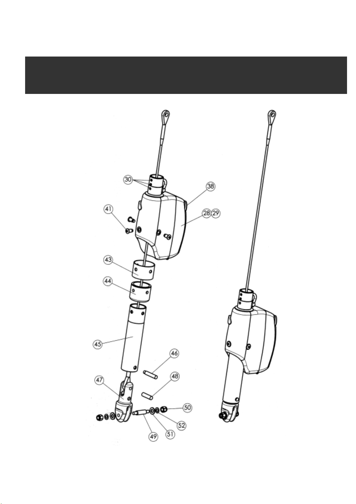
FITTING THE GEAR MOTOR
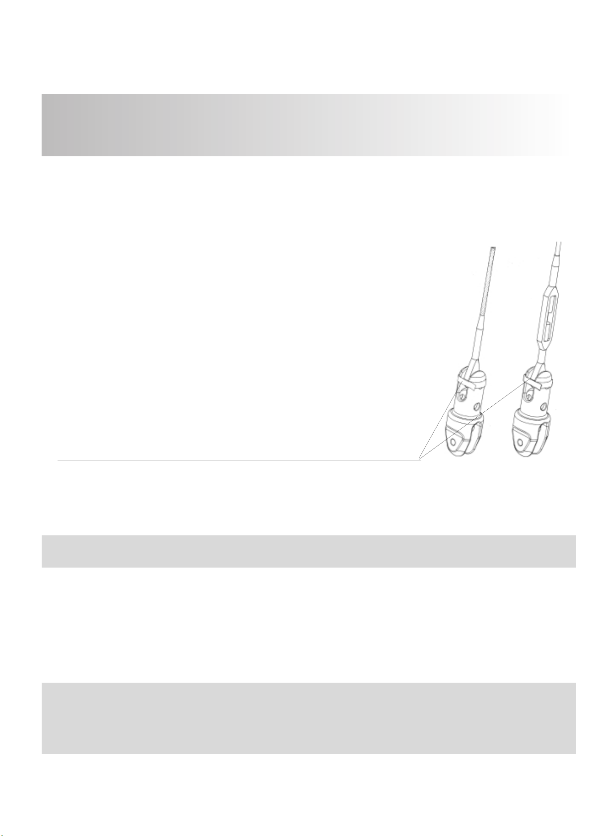
1 - For models 42 only, if t e system as been delivered wit a turnbuckle cylinder (52) - optional “I”
version:
• remove t e s ape adapter * (32) from t e gear motor,
• fit it at t e top of t e turnbuckle cylinder (52), align t e 3 oles in t e s ape adapter wit t e 3
corresponding t readed oles in t e cylinder.
• fit t e turnbuckle cylinder (52) at t e top end of t e gear motor, and screws (54).
* T e inside s ape of t e s ape adapter s ould matc t e outside
s ape of t e extrusions (round C 42, or foiled R 42).
2 - Depending on boat’s design t e stem ead c ainplate may ave been
constructed in eit er at wart -s ips or longitudinal direction. T e stainless steel
tube (45) s ould be fitted into t e gear motor in t e correct position in order
to ensure t at t e andle socket (38) in t e gear motor is facing backwards.
3 - Slide up t e gear motor over t e bottom of t e stay until t e bottom
forestay terminal is easily accessible.
4 - Slide up over t e bottom end of t e stay in t is order :
• T e stainless steel ring (44) fitted over t e anti corrosion bus ing (43)
• T e stainless steel tube (45)
5 - Take t e forestay bottom terminal t roug and out of t e bottom end of t e
stainless steel tube, and fit t e bottom eye onto t e upper ole of t e toggle (47).
Retain t e pin (48) in t e ole of t e toggle (45) wit ad esive tape.
6 - Keep t e gear motor raised (wit a alyard if t e system is fitted on a standing stay).
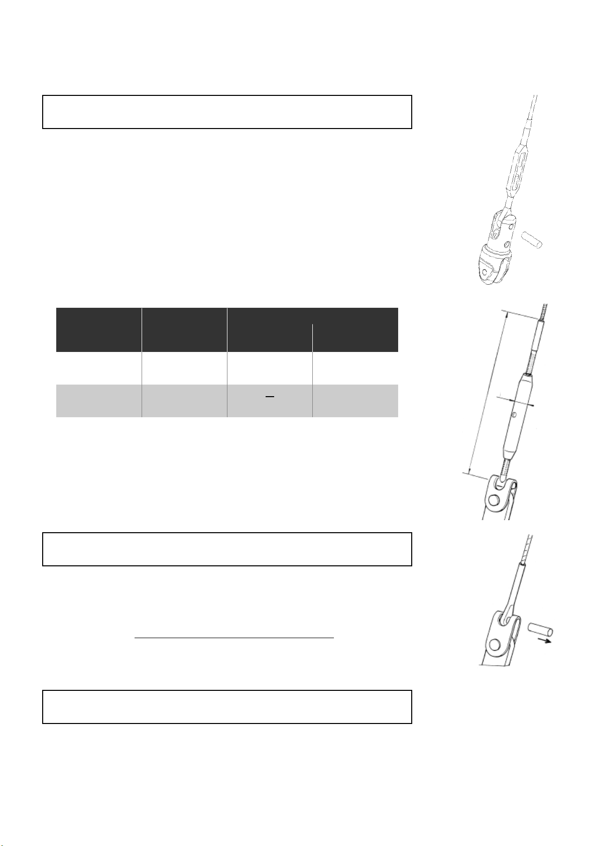
7 - Fit t e toggle (47) over t e c ainplate wit t e t readed clevis pin (49) supplied,
fit t e was ers (51) and t e locknuts (50).
8 - Adjust tension of turnbuckle (if fitted).
9 - Lower t e stainless steel tube (45) over t e toggle, and fit t e clevis pin (48) supplied (t e one wit
a ead) to connect t e stainless steel tube (45) onto t e lower ole of t e toggle (47).
10 - Lower t e gear motor over t e stainless steel tube (45) and fit t e 3 screws (41) to attac t e gear
motor onto t e stainless steel tube.
11 - During final assembly of t e extrusions, slide t em vertically into t e gear motor (or turnbuckle cylinder
if any) so t at t e black mark on t e lower extrusion is level wit t e top of t e s ape adapter (32). Fit
t e 3 set screws (30) to attac t e bottom end of extrusions.
8
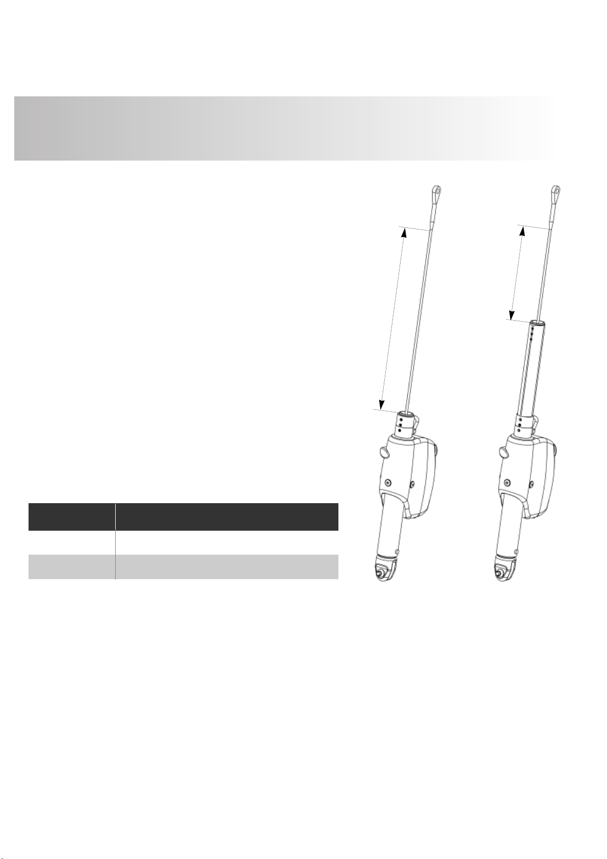
Properly secure t e turnbuckle to ensure t at it will NOT unwind w en operating t e system.
CAUTION!
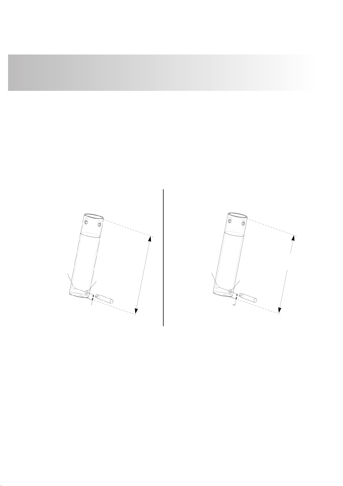
W en adjusting your turnbuckle more open, please do not unwind and extend t e turnbuckle
longer t an t e maximum allowed lengt . Remind in case t e stainless steel tube as been s ortened,
ìNî dimension will be reduced accordingly. Please refer to eadboard 1.