progeo CARBOMAX User manual

REHATEAM s.r.l.—vicolo Negrelli 5—31040 Castagnole di Paese TV - www.rehateamprogeo.com Service Manual CARBOMAX 1
S E R V I C E M A N U A L
CARBOMAX
Rev. 0 - 06/05/2020
SERVICE MANUAL
ENGLISH

REHATEAM s.r.l.—vicolo Negrelli 5—31040 Castagnole di Paese TV - www.rehateamprogeo.com Service Manual CARBOMAX 2
SERVICE MANUAL
CARBOMAX
GENERAL WARNINGS
ANY ADJUSTMENT CAN BE CARRIED OUT EXCLUSIVELY BY QUALIFIED
AND AUTHORIZED BY REHATEAM® PERSONNEL.
It is forbidden to carry out any modifications, even when possible, to the original
design.
Any adjustments and/or any modification that is carried out by non-authorized
personnel will immediately void the warranty on the product and it relieves
RehaTEAM® from any responsibility on any malfunctioning and/or damage due
to such adjustments/modifications.
Always contact RehaTEAM® and its technicians for any non-standard
requirements or modifications to allow them to evaluate such modifications and
verify that they will not compromise the normal and safe use of the wheelchair.
Any modification of the original parameters and set up could seriously
compromise the safe operation of the wheelchair causing damage to both the
user and the wheelchair itself.
After every adjustment made to the wheelchair, check carefully that all parts are
correctly fixed. Check that all screws and nuts are tightened and that all moving
parts are functioning correctly.
After any adjustment, always test the wheelchair before giving the product to
user and/or his/her attendant.
RehaTEAM® disclaims any responsibility for damage to the product or the peo-
ple due to any modification that is not properly performed or that, in any case,
does not guarantee safety to the user.

REHATEAM s.r.l.—vicolo Negrelli 5—31040 Castagnole di Paese TV - www.rehateamprogeo.com Service Manual CARBOMAX 3
SERVICE MANUAL
Page adjustment
04 FRONT HEIGHT Caster on fork
05 FRONT HEIGHT Sliding system
06 FORK ANGLE
07 DIRECTIONALITY
09 REAR HEIGHT
10 SETTING (point of balance)
11 CAMBER AND CONVERGENCY
13 BRAKE
14 BRAKE SPACING
15 FOOTPLATE DISTANCE tubes with holes
16 FOOTPLATE DISTANCE sliding system (until 2018)
17 FLIP BACK FOOTPLATE
18 BACKREST HEIGHT Aluminium or titanium backrest
19 BACKREST HEIGHT Carbon fibre backrest
20 BACKREST ANGLE
21 QUICK RELEASE AXLE (rear wheel)
CARBOMAX

REHATEAM s.r.l.—vicolo Negrelli 5—31040 Castagnole di Paese TV - www.rehateamprogeo.com Service Manual CARBOMAX 4
FRONT HEIGHT
caster on fork
The entity of the adjustment obviously depends on the caster and fork’s sizes.
Screw off the bolt Vwhile holding the other.
Remove the axle P.
Position the caster to another hole, insert the axle and fix the bolt Vholding the one
on the other side.
Pay attention to the spacers between caster and fork.
SERVICE MANUAL
V
V
P
It is advisable to spread a
drop of mild lock thread
glue on the bolts V.
Fork
height
Holes intervals –12,7 mm
Sport –2 holes –h. 88
Piccola –3 holes–h. 112
REHATEAM s.r.l.—vicolo Negrelli 5—31040 Castagnole di Paese TV - www.rehateamprogeo.com Service Manual CARBOMAX 5
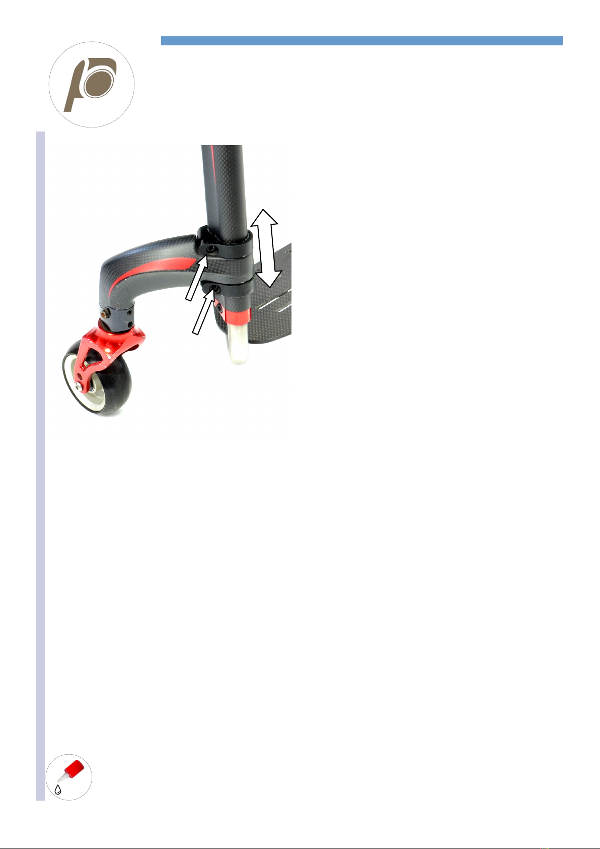
FRONT HEIGHT
Sliding system
SERVICE MANUAL
It is advisable to spread a
drop of mild lock thread
glue on the bolts V.
A
Work on a flat and even surface
Loosen the two bolts A.
Slide the support upward or downward to the desired height.
Tighten the two bolts A.
Repeat the same operations on the other side making sure the
height is the same.
The two front wheels must be touching the ground
Remember that the front height adjustment can affect the seat
inclination, so it is necessary to check and adjust the fork angle.

REHATEAM s.r.l.—vicolo Negrelli 5—31040 Castagnole di Paese TV - www.rehateamprogeo.com Service Manual CARBOMAX 6
SERVICE MANUAL
It is advisable to pread a
drop of mild lock thread
glue on all grab screws G.
WORK ON A FLAT AND EVEN SURFACE
Whenever the seat height is changed or as periodic maintenance, check the fork angle and, if necessary, adjust it in order to have the fork
axis perpendicular to the ground.
The adjustment is possible by means of the four grab screws G1, G2 and G3 that make the axle Pturn on the fulcrum F.
P
To turn the fork
frontward
Loosen G2.
Screw G1 and G3
Perpendicularity
You can check the perpendicu-
larity with the help of a square
(or similar) vertically aligned to
the caster turned 90° with re-
spect to the driving direction of
the wheelchair
To turn the fork
backward
Loosen G1 and G3
Screw G2
To adjust the fork, once you know the direction (frontward or backward) towards which it is necessary to move the fork’s axle, proceed as
above-mentioned until reaching the correct angle.
You can also measure the perpendicularity by turning the fork by 360°: during the full turn, the wheel has to touch the surface in all posi-
tions.
If a headless bolt results hard to unscrew, DO NOT FORCE IT, but try to loosen the other two first.
If the fork’s axle (the axle P) results hard to move, slightly loosen the bolt of the fulcrum F(remember to screw it after adjust-
ment).
Once you reach the correct angle, screw all three headless bolts all the way down to the axle P, but without tightening.
In order to fix the system, tighten first one and then the other less than a quarter of a turn at once, the grab screws G1 and G2 (the front
ones) checking the perpendicularity; in fact, it may slightly change during this phase.
Should that happen, correct the angle proceeding in the same manner.
When you have tightened both headless bolts G1 and G2, you can tighten the headless bolt G3.
Check the perpendicularity again and, if necessary, correct it.
FORK ANGLE
G1
F
G2 G3
P
Rotation when
screwing
G1 and G3
Rotation when
screwing
G2 and G3
90°
G2
G1
G3
G1
F
G3
G2
F
G1
G2
G3

REHATEAM s.r.l.—vicolo Negrelli 5—31040 Castagnole di Paese TV - www.rehateamprogeo.com Service Manual CARBOMAX 7
SERVICE MANUAL
DIRECTIONALITY
A very important aspect of any wheelchair is its directionality.
To check if the wheelchair goes straight, sit on it, push it and let it go until it stops.
If something is wrong, the slower the wheelchairs moves forward (momentum close to nothing), the more likely it turns right or left. There-
fore, if no or irrelevant turn occurs, the wheelchair is properly adjusted.
Cause Reason Solution
SURFACE The surface where the test is being performed is not even
and flat
Test the chair on even and flat surface
REAR WHEELS
The rear wheel are not equally inflated Inflate both tyres at the same pressure
The tyres of the two rear wheel are different or differently Change the tyres
The rear wheels are not adjusted at the same height Adjust the rear wheel height
The camber of right and left wheels are different or differ-
ently adjusted
Adjust the camber.
The wheel, when turning, touches the side guard or the
brakes
Fix or replace the side guard. Add spacer on the
receiver. Adjust the brake.
The wheels doe not turn smoothly Clean or change the bearings
FRONT WHEELS The casters are not adjusted at the same height Adjust the front wheels at the same height
The tyres of the two front wheels are different or differently Change the wheels
The fixing bolts of the fork/fork support/clamp are loosened Check and tighten all fixing bolts
The caster does not turn smoothly Clean the bearings.
Either or both forks are not adjusted so as their axis is per-
pendicular to the ground.
Adjust the fork axis inclination.
FOOTPLATE The footplate tubes are adjusted at different height. Adjust the tubes at the same height
If the wheelchairs does not go straight, in most cases the reason
is the fork angle adjustment.
However, before working on the fork angle adjustment, check all
the points above mentioned.
First, make the test along a flat even surface to check the direc-
tionality.
1 The correct adjustment has both forks perpendicular to the
ground, that is, their axis at 90°.
2 If the wheelchair TURN RIGHT, the cause is one or more of
the following:
The RIGHT fork is tilted inwardly and/or backward
The LEFT fork is tilted outwardly and/or frontward
3If the wheelchair TURN LEFTT, the cause is one or more of
the following:
The LEFT fork is tilted inwardly and/or backward
The RIGHT fork is tilted outwardly and/or frontward
90° 90° 90° 90°
1
2
3
Follows next page

REHATEAM s.r.l.—vicolo Negrelli 5—31040 Castagnole di Paese TV - www.rehateamprogeo.com Service Manual CARBOMAX 8
SERVICE MANUAL
DIRECTIONALITY
ADJUSTING THE DIRECTIONALITY
Check that the two forks are perpendicular to the ground. If they are not,
proceed with the adjustment of the fork angle following the instructions
on the sheet FORK ANGLE ADJUSTMENT.
If both forks axis are correct but the wheelchair still turns right or left, it
means that the latitudinal angle is not perfect.
This may be due to hit, to improper pressure exercised on the fork or its
support, or to a tiny imperfection among all parts fixed together due to
their manufacturing tolerances.
You can fix the fork axle P in three different angles to correct the direc-
tionality.
Loosen all four grab screws G, remove the bolt Fand slide off the fork
complete with the axle P.
The axle has two side hollows Bwhere you have to cast the flat inserts
C0 or the 1° titled inserts C1 that are recognizable thanks to two dots.
With the flat inserts C0, the axle keep its original inclination.
With the tilted inserts C1, the axle tilts by 1° right or left according to
how to cast them in the hollows—see images.
Note: you can cast the inserts only as indicated in these images.
Once you have casted the inserts C0 or C2, it is advisable to try to
screw the bolt Fto check there is no difficulty. Sometimes, in fact, the
holes of the inserts may have working burr that make the bolt hard to go
through.
To mount the fork unit. Insert the axle Pin the fork support paying atten-
tion to the orientation of the same axle. In fact, the axle is not straight,
but it shows a bend. Such bend must be facing to the rear of the wheel-
chair.
Insert and screw the bolt Fwithout tightening it much (it is enough to screw it up to stop).
Adjust the fork angle —see sheet “fork angle”.
Note. This type of adjustment can take place even at original assembly, therefore, you may find the in-
serts C0 on one axle and C1 on the other, for instance.
The wheelchair is not supplied with supplementary inserts, therefore, it will be necessary to order them
when needed.
Axles without inserts
Until 2019 the axles had no inserts C0 or C1. There were 0°, 1°rh and 1°lh axles.
To adjust the directionality, it is necessary to change the axle.
B
P
0° XY1°
Y X X Y
X Y Y X
0° 1° 1°
P P P
C0 C1
F
G3
F
G1
G2
SIDE VIEW
P
FRONT REAR
C0 oC1
P
C0
or
C1
C0
or
C1

REHATEAM s.r.l.—vicolo Negrelli 5—31040 Castagnole di Paese TV - www.rehateamprogeo.com Service Manual CARBOMAX 9
SERVICE MANUAL
REAR HEIGHT
Adjustment every 1 cm.
Remove the bolt Aon both sides of the wheelchair. The inner plate of the clamp-
support Band the nut will come off.
Move the frame up or down until aligning the hole of the support B(not visible in the
picture because it lays between the plate and the frame, but it is indicated by the
dotted rectangle) with one of those of the plate C.
Then insert the bolt A, the inner plate and the nut in its location.
When tightening this bolt, check that the inner plate of the clamp does not turn (you
can hold it with your fingers), in fact, if it turns, the clamp will not take hold of the
frame properly.
Finally tighten the bolt.
There is no need to use a spanner to hold the nut; in fact, its location on the inner
clamp will hold it.
Check/adjust the brakes.
Remember that the rear height adjustment can affect the seat inclination, so it is
necessary to check and adjust the fork angle.
The rear height adjustment can also change the point of balance (setting) of the
wheelchair.
If necessary, adjust the setting.
You will never need to modify the side guard.
Inner plate
of the clamp B
Nut
Part of the clamp B
leaning against the plate
Part leaning
against the plate
Inner plate
B
C
A
A
B

REHATEAM s.r.l.—vicolo Negrelli 5—31040 Castagnole di Paese TV - www.rehateamprogeo.com Service Manual CARBOMAX 10
SERVICE MANUAL
SETTING (point of balance)
Remove the rear wheel.
Loosen the bolt Aof the front support Band put the wheel on.
Repeat the same operations on the other side of the wheelchair.
Loosen the bolt C of the rear support Dof both plates.
There is no need to use a spanner to hold the nut; in fact, its location on the inner clamp
will hold it.
The front supports integrate the brake clamp and they also fix the front axle.
The front axle is not necessary if the seat is of the type ” rigid in carbon fibre”.
Slide the frame frontward or backward through the clamps to the desired position .
If the frames are too hard to move, loosen the bolts as much more as it is necessary.
It is possible to adjust the setting every millimetre.
Once reached the desired setting, tighten the bolts Aand Bon one side first .
Then measure the distance Xbetween the rear side of the rear support and the backrest
plate.
Adjust and fix the other side respecting the same distance.
When tightening each bolt, check that the inner plate of the clamp does not turn (you can
hold it with your fingers), in fact, if it turns, the clamp will not take hold of the frame proper-
ly.
It may be possible to scratch the frame, so it is advisable to proceed with care and do not
force the system.
Remember that the setting adjustment can affect the seat inclination, so it is necessary
to check and adjust the fork angle.
The predetermined settings that appear in the order form approximately have the following
distance D(from the backrest’s axis to the wheel’s axis):
Prudential 9.0 cm; Standard 10.5 cm; Active 12.0 cm; Extreme 13.5 cm
Following the instructions above mentioned, you can reach a particularly prudential setting
up to 5 cm (with distance X= 0, rear support in contact with the backrest plate).
A
B D
C
X
D
D
A C
Il supporto anteriore integra il supporto
freno e fissa l’asse anteriore.
B
B
Piattino interno del supporto con dado
incassato

REHATEAM s.r.l.—vicolo Negrelli 5—31040 Castagnole di Paese TV - www.rehateamprogeo.com Service Manual CARBOMAX 11
SERVICE MANUAL
CAMBER AND CONVERGENCY
The hole of the cambered receiver, since it is inclined, is not centered.
Therefore, check the wheel receiver its narrow edge looking upward and its wider edge down. If opposite, the convergence is oppo-
site, too (the wheels are opening apart at top!).
At 30 cm from the floor, take the measure centre-to-centre between the two tyres in front and at rear.
If the two measures are equal or the front one is slightly narrower (max. 5 mm), you have a good convergence as drawing 2 or 3.
If different, you have to adjust the convergence.Se differente, è necessario regolare la campanatura.
Follows next page
WORK ON A FLAT AND EVEN SURFACE
The wheel receiver gives the rear wheel camber (cambered receiver).
The two wheel receivers are fixed to the rear axle, thus, to adjust the convergence, it is necessary to turn the axle.
The drawing 1shows same inclination (camber) of both rear wheels.
With cambered wheels, it is necessary to check/adjust the convergence, the distance between the two wheels in front and at rear.
The drawing 2 shows the aerial view of the wheels and the front distance DA is equal to the rear distance DP, while the drawing 3,
DA is narrower than DP by maximum 5 mm.
We can say that a good convergence has the front distance DA equal to or slightly narrower than the rear distance DP.
DA must not be wider than DP. In such case, the fluency of wheelchair will not be good.
RECEIVER
Narrow side up
Wide side down
30 cm
FRONT REAR
DA DP

REHATEAM s.r.l.—vicolo Negrelli 5—31040 Castagnole di Paese TV - www.rehateamprogeo.com Service Manual CARBOMAX 12
SERVICE MANUAL
CAMBER AND CONVERGENCY
Take the measures again and if necessary, repeat the same operation until you reach the correct convergence, se previous page.
If the clamp moved when you loosened the fixing bolts, position the axle’s end (not the receiver) at 3 mm and fix one side, first.
First tighten the two bolts Balternatingly and then the bolt/nut C.
Warning: if you reverse that sequence, the lock plate may crack it its thinner part. Finally, screw the grab screw A.
Before fixing the other side, check the front wheels (considered already adjusted at the same height) are both touching the ground. If one
do not touch, turn the frame on axle on its loosened side to the necessary extent.
If the quick release axle of the rear wheel hardly or do not pass through the receiver, loosen A, B and Cand remove it. Then, tighten all
parts again, but first pass the hole with a ½” reamer to remove any possible tiny deformation (see also adjustment sheet “quick release
axle”).
It may be a little harder to position and fix the other side due to the pressure given by the seat canvas, but you have to respect the same
distance.
Check the measure from a fix point of the frame to the centre of the tyre on each side.
Should there be a difference greater than 2-3 mm, check the distance between clamp and axle as above
mentioned.
If necessary, correct the adjustment.
2
1 3
2° receiver
4° receiver
Loosen the grab screw A and the bolt/nut C.
Loosen the above mentioned screws just enough to let you turn the rear axle with your hand but without the clamp
sliding along the axle. If that occurs, you can continue with the adjustment. You will fix that later.
Turn the rear axle (clockwise or anticlockwise) and observe how and to what extent the wheels move.
A good reference is the bolt D, in fact its axis, should be perpendicular to the ground, except for the 4° receiver
fixed in the centre position (2) which is rotated by 90° with respect to the other two positions (1 and 3); in such
case, the bolt D should be parallel to the ground.
Thinner part of the plate
3 mm
D
A
B
B
CC
D

REHATEAM s.r.l.—vicolo Negrelli 5—31040 Castagnole di Paese TV - www.rehateamprogeo.com Service Manual CARBOMAX 13
SERVICE MANUAL
BRAKE
WHEN ADJUSTING THE BRAKES, THE TURES MUST BE INFLATED TO THE CORRECT PRESSURE (except solid tyre)
The position of the brake depends on the position of the rear wheel.
Loosen the headless bolt Alocated in the lower side of the support B.
Position the brake-knurled rod Pat a distance Dof a few millimetres and parallel to the
ground.
Temporarily tighten the headless bolt Aand try the brake out to check if the adjustment is
good.
If necessary, repeat the same operation to reach the good adjustment.
A good adjustment has the brake not too hard to engage but braking, so you will have to
find the suitable compromise.
Once reached the correct position, tighten the headless bolt A.
Carry out the same operation on the other side.
The adjustment for the sport brake is the same except for the distance D, in fact, the brake,
in its resting position is far away from the tyre. Just make a few tries
Note: if the frame s rather short (short seat depth) there may be interference with the front
curve of the frame. In that case, it is necessary to move the rear wheel backward (point of
balance) as much as necessary (see adjustment sheet ”setting”)
A
B
A
B
In order to have a stable fixing of
the brake, it is possible there is a
small block that is located within
the opening of brake tube.
The clamp must always tighten
such small.
X
REHATEAM s.r.l.—vicolo Negrelli 5—31040 Castagnole di Paese TV - www.rehateamprogeo.com Service Manual CARBOMAX 14
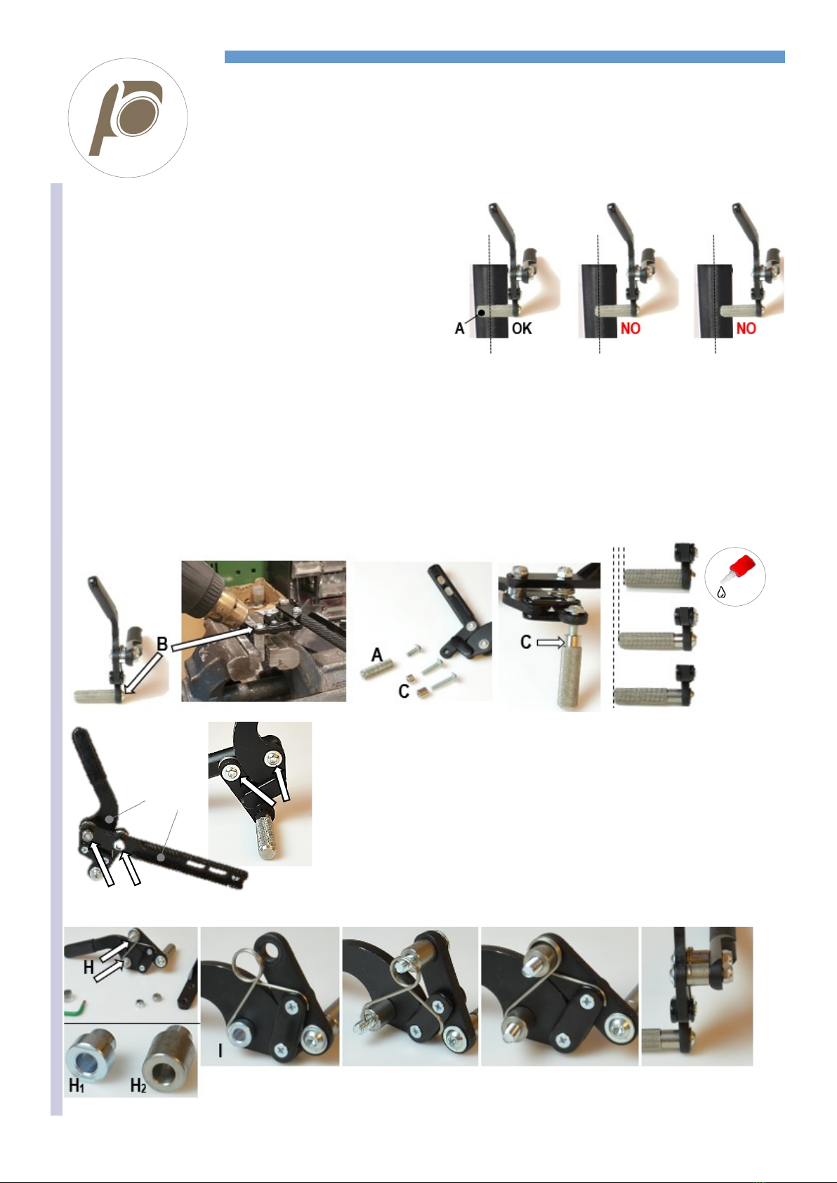
SERVICE MANUAL
BRAKE SPACING
B
Spread
some strong
thread lock
glue on the
bolt B.
In several cases, the distance between the tyre and the frame can be such
as to make need moving the knurled rod Pmore external.
When originally assembling the wheelchair, such possible modification is
already taken into account.
In case of a post-sale modification that results in the rear wheels being
more external (from 0° to 2° or 4° camber; seat width enlargement; a dif-
ferent wheel), the brake may not work efficiently anymore, therefore, you
will have to move the knurled rod. The brake is efficient if the knurled rod P
is at least 5 mm beyond the tyre’s mid-line.
In all cases, check the brake efficiency.
Remove the bolt B. In order to remove it, put the knurled rod in a vice and heat it with a hot air blower because the bolt is locked with strong
lock thread glue. DO NOT FORCE WHEN UNSCREWING IT, you may damage the bolt’s head irremediably.
Once you have removed the bolt, the knurled rod comes off, too. Replace the bolt Baccording to the spacer C(7 or 11 mm) you will add.
Put some strong lock thread glue on the bolt Band assemble the spacer Cand the knurled rod A.
Put the knurled rod in a vice and tighten the bolt B hard.
It is also possible to move the brake structure Efrom the adjustment rod F.
Remove the two nuts Gand then the two bolts B.
Remove the spacers Haround which the spring is assembles.
Observe how the spring is assembled because you will have to assemble it back later in
the same way (you can always have a look at the other brake that is symmetric).
Insert the spacers H(H1= original; H2= 7 mm longer).
Position the spring and assemble the structure to the adjustment rod.
Start screwing the two bolts Ball the way down and then the two nuts G.
Should the brake movement be hard, slightly loosen the bolts B.
E F
G
B

REHATEAM s.r.l.—vicolo Negrelli 5—31040 Castagnole di Paese TV - www.rehateamprogeo.com Service Manual CARBOMAX 15
SERVICE MANUAL
FOOTPLATE DISTANCE
Tubes with holes
Screw off the bolt A of both side of the frame.
Slide the tubes to the necessary height.
Make sure the height of the two sides is the same.
Insert the bolt Apaying attention to fitting it with no effort into the
threaded hole Bon the rear side of the support C.
The footplate tube’s holes and the hole of the support Bmust be
aligned.
Finally, tighten the bolt Aon both sides of the frame.
Do not force screwing the bolt, you may damage the thread of the
hole B. Should that occur, you can remedy by pass the threaded hole
with a M5 tap starting from the rear side of the support. If the thread is
too damaged to be repaired, you can pass the hole with a 5 mm drill
bit and fix the tube with a longer bolt, washer and nut.
You can change the support Conly if you cut the frame 3 cm and
glue, with epoxy glue, the new support.
C
B
ANTERIORE POSTERIORE
(A)
C
A
A

REHATEAM s.r.l.—vicolo Negrelli 5—31040 Castagnole di Paese TV - www.rehateamprogeo.com Service Manual CARBOMAX 16
SERVICE MANUAL
FOOTPLATE DISTANCE
Sliding system (until 2018)
Adjustment with sliding system.
Loosen the bolt Aof the clamp on both sides.
With a rubber or plastic mallet, gently hit on the upper or lower points that are indicated by the black arrows according to the adjustment you
need to carry out.
Once you reach the desired height, tighten the bolt Aon one side.
Check the wide side of the footrest plate is parallel to the ground.
If necessary, raise or lower the tube on the side that is not fixed yet. Finally, tighten the bolt Aof the second side.
After each adjustment, check that:
Between the lower side of the footplate and the ground, there is at least a 2 cm gap.
There is no interference between footplate and casters.
The height adjustment of the footplate can affect the directionality of the wheelchair, in fact, if the footplate is slightly tilted on either side, the
wheelchair will go right or left. In such case, correct the height of the right or left tube.
A
A
A

REHATEAM s.r.l.—vicolo Negrelli 5—31040 Castagnole di Paese TV - www.rehateamprogeo.com Service Manual CARBOMAX 17
SERVICE MANUAL
TUBULAR ALUMINIUM FOOTPLATE
Both for tubes with hole and for sliding system
B
B
D C
B
B
B
E
Angle adjustment.
You can adjustment the inclination by changing the leaning point of the footplate.
Flip the plate back.
On the horizontal part of the footplate tubes there is threaded rivet that works as leaning
point B.
A bolt Cand the washer Dis usually present on this point.
Therefore, you can adjust the inclination by increasing or decreasing the thickness over the
rivet.
To increase the inclination, remove the bolt Cand add other washers Dor a suitable spacer.
Finally, insert and tighten the bolt C.
To reduce the inclination, remove the bolt Cand remove the necessary washers/spacers.
Finally, insert and tighten the bolt C.
Without the bolt C, you can reach the minimum inclination.
To eliminate the possible noice due to the contact between the plate and its leaning point,
you can simply stick rubber or similar pad under the plate where necessary.
Footplate position
Only internal.
Adjustment of flip-back movement
When you loosen the two bolts E, the movement becomes easier.
When you tighten the two bolts E, the movements becomes harder.
If you tighten the two bolts very hard, the movement is almost stuck.
Note: you can also fix the plate if you drill two holes aligned to the leaning points Band fix it
with the two bolts C.
At each adjustment, it is advisable to spread a
drop of mild lock thread glue on the bolts C.

REHATEAM s.r.l.—vicolo Negrelli 5—31040 Castagnole di Paese TV - www.rehateamprogeo.com Service Manual CARBOMAX 18
SERVICE MANUAL
BACKREST HEIGHT
Aluminium or titanium backrest
min. 4 cm
A
Plastic adaptor
Remove the backrest upholstery and slide up the protecting sleeves of the backrest bands along the tubeuntilthefixingscrews are visible.
If the bolt is not accessible, remove the mudguard if it is removable or tilt the backrest backward by means of its adjustment system (see
backrest angle adjustment sheet).
Remove bolt and nut A and raise orlowerthebackrest tubes tothe desired height.
If the minimum height you can reach is not enough, it is necessary to cut the lower side of the.
If the maximum height you can reach is not enough, it is necessary to change the tube.
Warning: to guarantee a good stability, between the fixing hole and the lower side of the tube, there should be at least 4 cm. If the tube is
cut, the lower hole will be only a few millimetres front the end of the tube; therefore, you should not use that hole, the next and, sometimes
even the third to fix the backrest height.
Replace the screws andtighten.
To reduce possible play and possible noise, you can put some sticky tape around the inner tube at its bottom and at its fixing point (or just
under it).
Note: if the backrest tube is in carbon fibre, follow the instructions of the adjustment sheet “backrest height—carbon fibre backrest”.
The titanium backrest structure includes a plastic adaptor, just follow the same instructions above.

REHATEAM s.r.l.—vicolo Negrelli 5—31040 Castagnole di Paese TV - www.rehateamprogeo.com Service Manual CARBOMAX 19
SERVICE MANUAL
BACKREST HEIGHT
Carbon fibre backrest
B 1a
1
1b
C
B
1
1b
Remove the backrest upholstery and slide up the protecting sleeves of the backrest bands along the tube untilthe fixingscrewsAare visible.
In the fixing point, you will also see a steel buckle B.
If the bolt is not accessible, remove the mudguard if it is removable or tilt the backrest backward by means of its adjustment system (see
backrest angle adjustment sheet).
Remove bolt and nut A.
The backrest tubes have only one hole that is originally drilled according to the height requested in the order form.
On the pictures above, you can see that the fixing point is the 1.
The point 1a could be a new hole to lower the backrest height and that is possible without creating problem (you may need to cut off the
bottom side of the tube), in fact, the hole 1will be underneath and within the tube of the backrest structure. While drilling the hole on the
tube, pay attention to aligning the handle grip (if present).
Should you cut off the bottom side the tube, insert the buckle Bon the tube and put a few turns of sticky tape Caround the extremity of the
tube to reduce a possible play.
Insert bolt and nut Aand tighten without overtightening to avoid damaging the carbon fibre.
The 1b, on the other hand, would be the point where to drill a new hole to increase the backrest height, but, by doing so, the
hole 1would be out of the backrest structure and it would create a situation of possible breakage of the tube during normal use
of the wheelchair. This operation is not allowed.
Warning: to guarantee a good stability, between the fixing hole and the lower side of the tube, there should be at least 4 cm.
The carbon fibre backrest tube is not suitable to fixing any clamps, such as those used for a postural system hardware.
Note: if the backrest tube is assembled on a aluminium or titanium backrest structure, follows these same instructions.

REHATEAM s.r.l.—vicolo Negrelli 5—31040 Castagnole di Paese TV - www.rehateamprogeo.com Service Manual CARBOMAX 20
SERVICE MANUAL
BACKREST ANGLE
Adjustment from 16° close, tilted frontward (74°) to 4° open, tilted backward (94°) with respect to 90° to the seat.
If you need to open (tilt backward) the angle, before proceeding, with the adjustment, fold the backrest, loosen the nut Cand screw the bolt
Bthat determine the end run, that it the point where it will lean on the frame. Such operations are not necessary when you need to close (tilt
forward) the angle.
The adjustment can be performed thanks to the two bolts Asliding along the slots through which they pass and fix the backrest tube.
Therefore, loosen the two bolts Aon both backrest plates, tilt the backrest to the desired inclination and securely tighten the bolts.
Now check the locking system.
If the locking pin Ddoes not lock, or there is too much play, it is necessary to adjust the end run bolt B.
Loose the nut C, fold the backrest and screw or unscrew the bolt B.
Open the backrest and check if it locks and its play.
To check the play, with the locked backrest, gently pull back it and forth.
If the play is still a lot, loosen the bolt B, whereas, if the backrest does not lock, screw the bolt B.
The correct adjustment is when the pin locks and the play is minimum. Then screw the nut Ctowards the tube.
Not only does the end run bolt Breduce the backrest play, but also it is very important as point of support of the backrest. In fact if it is badly
adjusted (a lot of play) the lock pin Dwill support all the backrest stress and it may be damaged or even brake.
Remember that the backrest angle can affect the point of balance of the wheelchair. In fact, with tilted backward backrest (open angle),
the wheelchair becomes less stable.
A
A
C
B
D
90°
74° 94°
Table of contents
Other progeo Wheelchair manuals

progeo
progeo ego User manual

progeo
progeo Joker User manual

progeo
progeo Tekna Tilt User manual

progeo
progeo JOKER JUNIOR 2.0 User manual

progeo
progeo Raptor User manual

progeo
progeo JOKER R2 User manual

progeo
progeo JOKER ENERGY User manual

progeo
progeo Exelle User manual

progeo
progeo Exelle Junior User manual

progeo
progeo TEKNA ADVANCE Series User manual

progeo
progeo Joker User manual

progeo
progeo YOGA User manual

progeo
progeo JOKER EVOLUTION User manual

progeo
progeo Basic Light User manual

progeo
progeo DUKE User manual

progeo
progeo Exelle User manual

progeo
progeo Physio Air User manual

progeo
progeo MOTOTRONIK User manual

progeo
progeo YOGA User manual

progeo
progeo Tekna Tilt User manual


