Norac UC4+ User manual
Apache 859, 790 (2000+) Enhanced Stability
Installation Manual
Spray Height Control System
Improving the competitiveness of Industry and Agriculture
throu
g
h Precision Measurement

Printed in Canada
Copyright 2005-08 by NORAC Systems International Inc.
Reorder P/N: UC4+BC+AP1-INST Rev F (Apache 859/790 (2000+) Enhanced Stability)
NOTICE
NORAC Systems International Inc. reserves the right to improve products and their specifications without notice and without
the requirement to update products sold previously. Every effort has been made to ensure the accuracy of the information
contained in this manual. The technical information in this manual was reviewed at the time of approval for publication.

TABLE OF CONTENTS
1INTRODUCTION..................................................................................................................................1
2GENERAL SYSTEM DESCRIPTION ..................................................................................................2
3PARTS LISTS ......................................................................................................................................3
4INSTALLATION PROCEDURE...........................................................................................................7
4.1EXISTING SYSTEM CHECK ...............................................................................................................7
4.2BOOM SPEED TEST........................................................................................................................7
4.3WING SENSOR INSTALLATION.........................................................................................................9
4.4MAIN LIFT SENSOR INSTALLATION..................................................................................................13
4.5ROLL SENSOR INSTALLATION.......................................................................................................14
4.5.1Boom Frame Roll Sensor Mounting......................................................................................15
4.5.2Intermediate Frame Roll Sensor Mounting ...........................................................................16
4.5.3Reference Frame Roll Sensor Mounting...............................................................................17
4.6HYDRAULIC INSTALLATION ...........................................................................................................18
4.6.1Valve Assembly.....................................................................................................................18
4.6.2Valve Mounting......................................................................................................................19
4.6.3Hydraulic Plumbing ...............................................................................................................20
4.7ELECTRICAL INSTALLATION..........................................................................................................21
4.8COMPLETING THE INSTALLATION ..................................................................................................24
5ELECTRICAL REFERENCE – CABLE DRAWINGS........................................................................25
5.1ITEM C01: 44662B-40 –SENSOR TRUNK CABLE .........................................................................25
5.2ITEM C02: 44668 –CABLE UC4 SENSOR BRANCH.......................................................................25
5.3ITEM C02B: 44664 –CABLE UC4 CAN NODE DUAL 5FT...............................................................26
5.4ITEM C05: 44674 –CABLE UC4 SENSOR ROLL BIAS ...................................................................26
5.5ITEM C10: 44650-12 –CABLE POWER BOOM CONTROL CASE IH 4260........................................27
5.6ITEM C11: 44658-07 –WIRING HARNESS UC3 BOOM CONTROL PIGTAIL TO SHROUD...................27
5.7ITEM C12: 44659D –CABLE VALVE PATRIOT/CASE IH 4260........................................................28

1
1INTRODUCTION
Congratulations on your purchase of the NORAC UC4+ Spray Height Control system. This
system is manufactured with top quality components and is engineered using the latest
technology to provide operating features and reliability unmatched for years to come.
When properly used the system can provide protection from sprayer boom damage, improve
sprayer efficiency, and ensure chemicals are applied correctly.
Please take the time to read this manual completely before attempting to install the system. A
thorough understanding of this manual will ensure that you receive the maximum benefit from
the system.
YOUR INPUT CAN HELP MAKE US BETTER! If you find issues or have
suggestions regarding the parts list or the installation procedure, please don’t
hesitate to contact us.
2
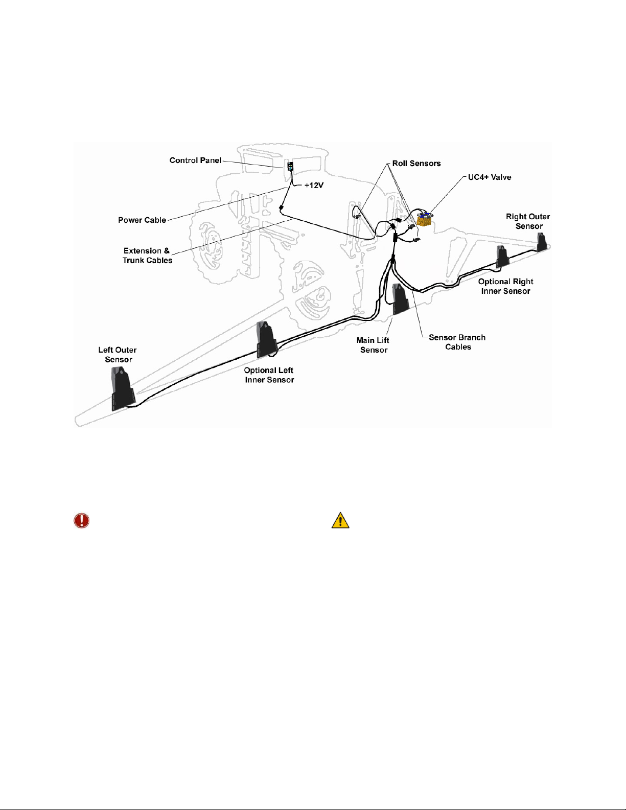
2GENERAL SYSTEM DESCRIPTION
Figure 1 depicts the general system layout of the UC4+ Sprayer Boom Control system.
Figure 1: System Components and General Location
NOTICE:
Every effort has been made to ensure the
accuracy of the information contained in
this manual. All parts supplied are selected
specially to fit the sprayer to facilitate a
complete installation. However, NORAC
cannot guarantee all parts fit as intended
due to the variations of the sprayer by the
manufacturer. Please read this manual
in its entirety before attempting
installation.
ATTENTION:
When installing the UC4+ Spray Height
Control system please be aware that at a
point in the installation your sprayer booms
will be inoperative until the installation is
complete. Any installation procedure
requiring boom movement will need
to be done first. Once the hydraulics
have been disconnected you must complete
the electrical installation before the booms
become operative.
Other manuals for UC4+
41
Table of contents
Other Norac Farm Equipment manuals

Norac
Norac UC4 Total Control User manual

Norac
Norac UC4.5 User manual

Norac
Norac UC4.5 User manual

Norac
Norac UC5 Topcon X30 User manual

Norac
Norac UC5 Topcon X30 User manual

Norac
Norac UC5 Sx275 User manual

Norac
Norac UC5 Topcon X30 User manual

Norac
Norac UCB Sx275 User manual

Norac
Norac UC4+ User manual

Norac
Norac UC4+ User manual
Popular Farm Equipment manuals by other brands

Schaffert
Schaffert Rebounder Mounting instructions

Stocks AG
Stocks AG Fan Jet Pro Plus 65 Original Operating Manual and parts list

Cumberland
Cumberland Integra Feed-Link Installation and operation manual

BROWN
BROWN BDHP-1250 Owner's/operator's manual

Molon
Molon BCS operating instructions

Vaderstad
Vaderstad Rapid Series instructions


