PROLUMIA 40010302 User manual

www.prolumia.com
LED PROFIT + LED PROFIT SEMI SHIELDED
40010302 Pro-Fit + Emergency mode (White)
40010312 Pro-Fit + Emergency mode (Black)
40010303 Pro-Fit + Microwave sensor + Emergency mode (White)
40010313 Pro-Fit + Microwave sensor + Emergency mode (Black)
40010322 Pro-Fit Semi shielded + Emergency mode (White)
40010332 Pro-Fit Semi shielded + Emergency mode (Black)
40010323 Pro-Fit Semi shielded + Microwave sensor + Emergency mode (White)
40010333 Pro-Fit Semi shielded + Microwave sensor + Emergency mode (Black)
OPERATING INSTRUCTION
GEBRUIKSAANWIJZING
MANUEL D’UTILISATION
INSTALAČNÍ NÁVOD
GEBRAUCHSANLEITUNG
+ EMERGENCY MODE
2
www.prolumia.com
ATTENTIE
OPGELET
TECHNISCHE DATA
TECHNISCHE INFORMATIE
Lees de volgende instructies zorgvuldig door om ervoor te zorgen dat de montagewerkzaamheden op de juiste manier
worden uitgevoerd. Bewaar deze instructies goed voor eventueel toekomstig gebruik.
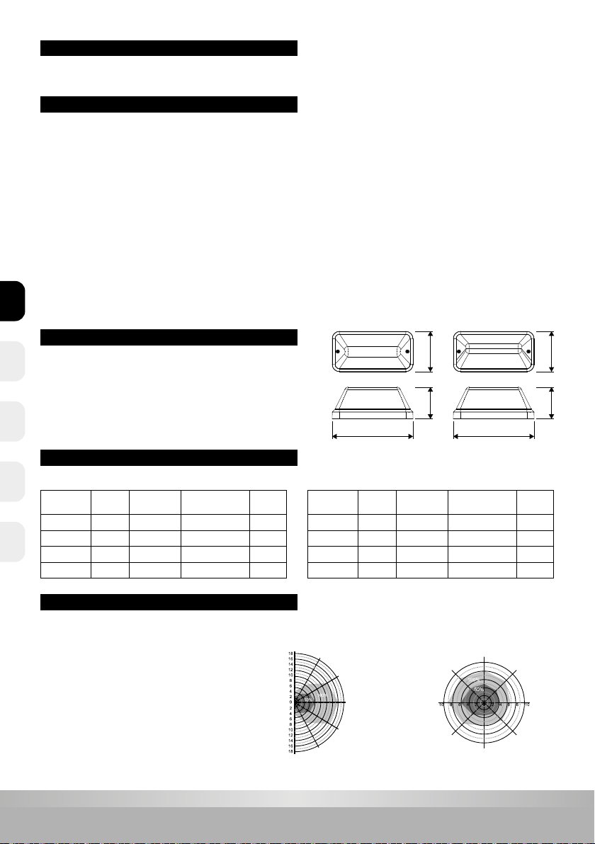
Standaard versie Half afgeschermde versie
MICROWAVE SENSOR BESCHRIJVING
Detectiebereik max. (D x H): 12m x 6m
Detectiegevoeligheid: 50% of 100%, instelbaar
Brandduur: 5sec - 10min, instelbaar
Daglicht aan: 5 - 50Lux, instelbaar of uitgeschakeld
Daglicht uit: 25 - 150Lux, instelbaar of uitgeschakeld
Stand-by periode (laag lichtniveau): 0 sec - +∞, instelbaar
Stand-by dim niveau: 10% of 25%, instelbaar
Montagehoogte plafond: 6m max.
Bewegingsdetectie (drempel): 0,3 ~ 3m/s
Detectiehoek: 150° (wandmontage),
360° (plafondmontage)
Voedingsspanning: AC 220-240V 50/60Hz
Lichtbron: SMD2835 LED
Accu: Ni-Cd Duur: 1 uur
Bedrijfstemperatuur: -10°C - +50°C (Sensor versie: tot max. +40°C)
Elektrische veiligheidsklasse: Klasse II
Artikelnr. Kleur Vermogen Lichtstroom
schakelbaar Sensor
40010302 Wit 7W 700Lm / 350Lm -
40010312 Zwart 7W 700Lm / 350Lm -
40010303 Wit 8W 700Lm / 350Lm Ja
40010313 Zwart 8W 700Lm / 350Lm Ja
Artikelnr. Kleur Vermogen Lichtstroom
schakelbaar Sensor
40010322 Wit 7W 500Lm / 250Lm -
40010332 Zwart 7W 500Lm / 250Lm -
40010323 Wit 8W 500Lm / 250Lm Ja
40010333 Zwart 8W 500Lm / 250Lm Ja
1. Het product dient te worden geïnstalleerd door gekwaliceerde personen. De installatie dient, voorafgaand aan de montage, spanningsloos
te worden gemaakt.
2. De installatiedraad moet minimaal 2 x 1,0 mm² zijn en worden aangesloten in overeenstemming met de laatste elektriciteitsvoorschriften van
IEE of volgens de nationale eisen.
3. Sluit de stroomtoevoer van de voeding af voordat u de accu vervangt.
4. Raak het elektronische circuit en de componenten niet aan.
5. Indien de autonomie van 1 uur niet meer wordt gehaald, dient de accu vervangen te worden.
6. Neem contact op met een erkende technische service center voor het vervangen van de accu en gebruik alleen originele onderdelen voor
andere reparaties.
7. Identicatie code van de accu productiedatum: ex.1810 --- 2018, week10.
8. Raak de LED’s niet aan tijdens installatie of onderhoud.
9. De LED lichtbron van de lamp kan niet worden vervangen. Het volledige product dient te worden vervangen als de lichtbron defect is.
10. Door zelfontlading neemt de lading van de accu, als deze niet op het net is aangesloten, langzaam af. Dit kan leiden tot schade aan de accu bij
langdurige spanningsloosheid. De hierdoor ontstane schade valt niet onder garantie.
11. Op veel bouwplaatsen kunnen stroomcircuits worden onderbroken op een ongecontroleerde en repetitieve basis tijdens de bouw. Accu’s
kunnen als gevolg hiervan leeglopen. Het frequent laden en ontladen van de accu zal de levensduur verkorten en kan leiden tot voortijdig
falen van de accu. De hierdoor ontstane schade valt niet onder garantie.
140110
280
140110
280
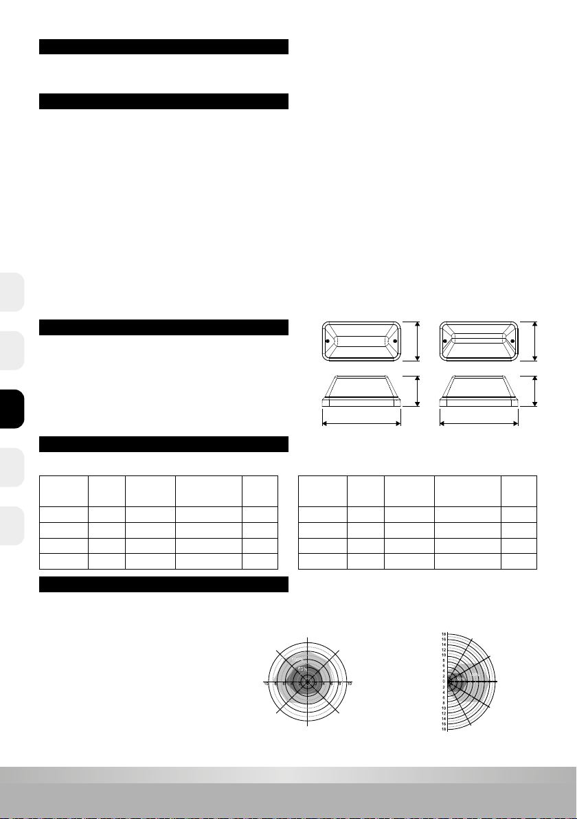
Bewegingssnelheid: 0,3m/s
Detectiebereik (m) plafondmontage
Voorgestelde montagehoogte: 3m
Bewegingssnelheid: 0,3m/s
Detectiebereik (m) wandmontage
Voorgestelde montagehoogte: 2m
NLENCZ FRDE
3
www.prolumia.com
MICROWAVE SENSOR INSTELLING PARAMETERS
Detectiebereik
Dit bepaalt het eectieve bereik van de bewegingsmelder en wordt
met de micro-schakelaars op de driver ingesteld. Wees er van bewust
dat het verminderen van de gevoeligheid ook het detectiebereik zal
verkleinen.
Stand-by periode
Bij de +∞ instelling zal het armatuur gedimd gaan branden op basis
van de instelling bij en de hoeveelheid omgevingslicht. Bij
bewegingsdetectie gaat het lichtniveau gedurende de nalooptijd
naar 100%.
Nalooptijd
Dit bepaalt de tijd dat het armatuur op 100% niveau blijft branden. Dit
kan worden ingesteld met micro-schakelaars op de driver. Tijdens het
installeren van het armatuur is de looptest-instelling (5s) handig om
de juiste werking en het bereik vast te stellen.
Stand-by Dim niveau
Instelling van de lichtstroom bij gedimd lichtniveau.
Als de DIP-schakelaar op‘Stand-by periode’ op +∞ staat,
is de standaardinstelling 10% en kan niet worden gewijzigd.
Daglicht
Met deze instelling kan worden bepaald bij welk daglichtniveau het
armatuur al/dan niet zal worden ingeschakeld bij bewegingsdetectie.
De fotocel functionaliteit kan ook worden uitgeschakeld.
NL EN CZFR DE

4
www.prolumia.com
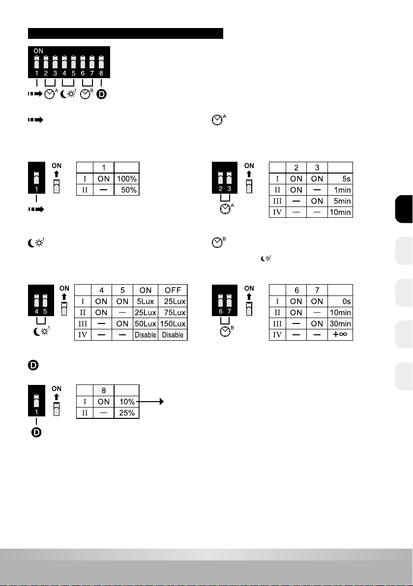
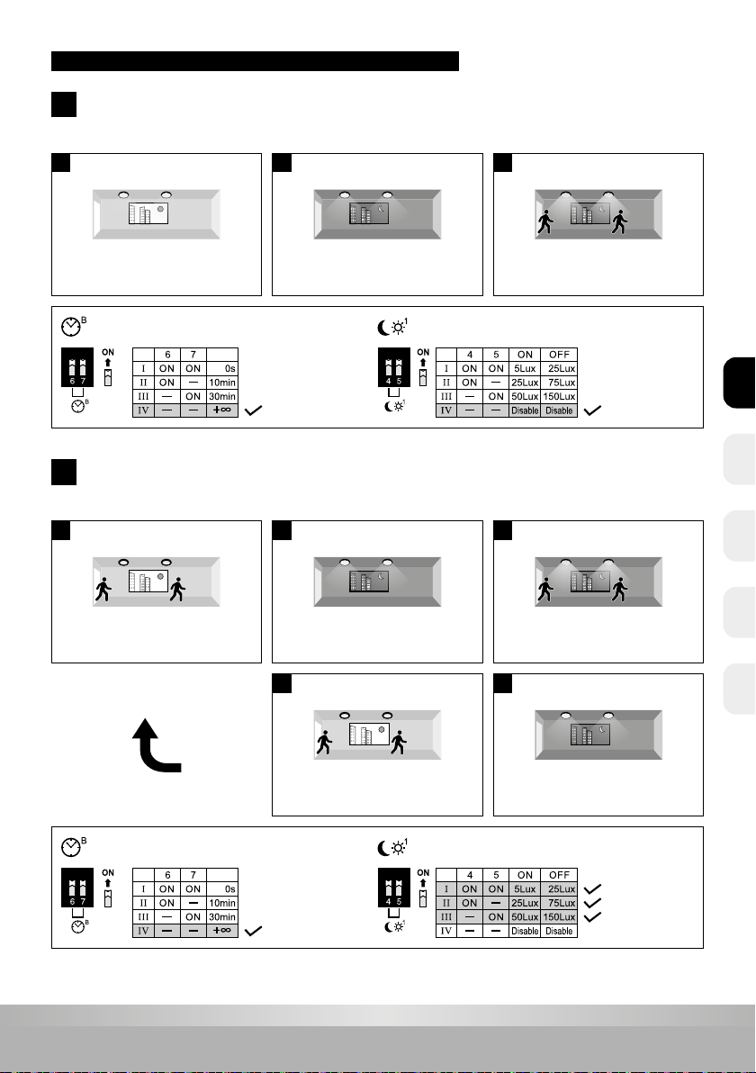
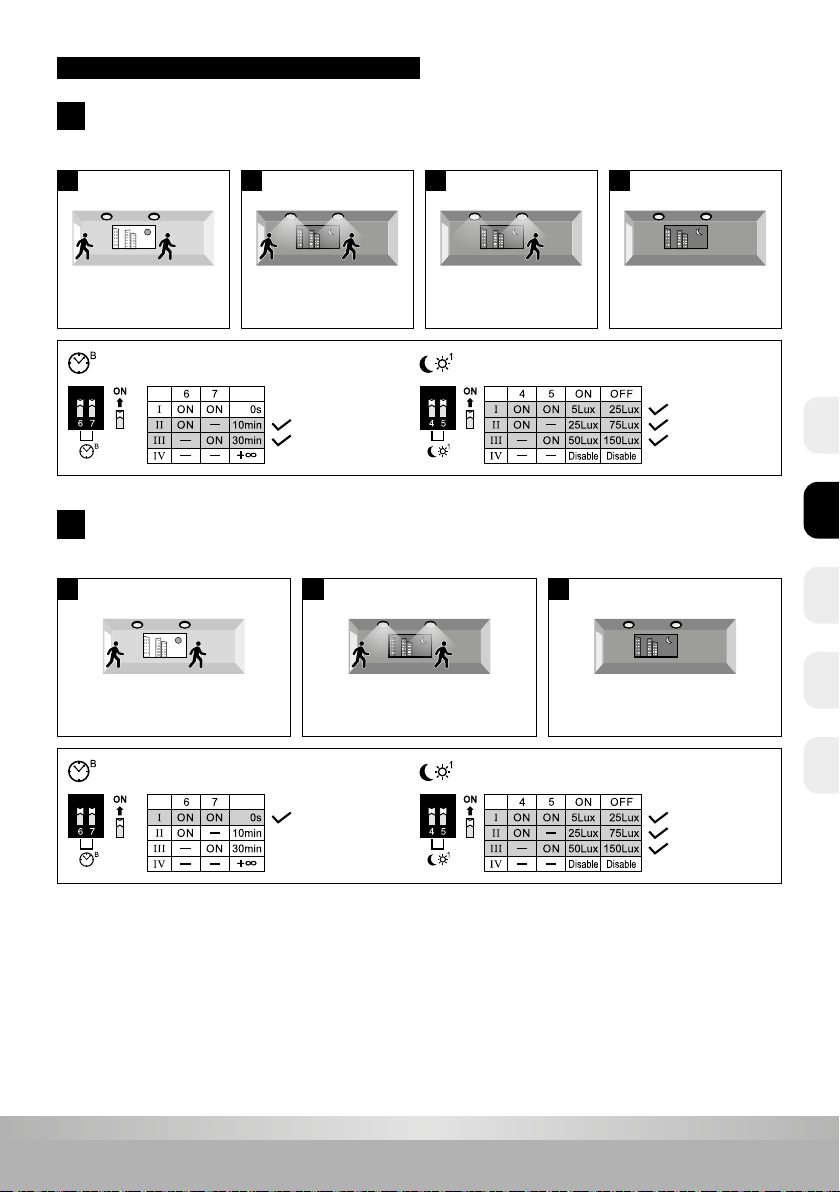
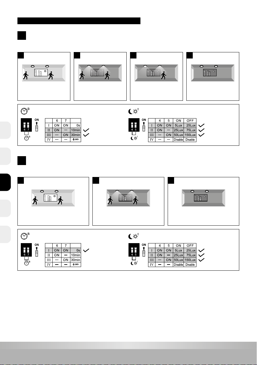
MICROWAVE SENSOR VOORBEELDEN VAN INSTELLINGEN
100% 100%
100% 100%
100%10%/25%
0% / 100% / 10% of 25%
0% / 100%
A
B
1
1
2
2
3
3
4
Stand-by periode (gedimd licht)
Stand-by periode (gedimd licht)
Daglicht
Daglicht
Uit bij voldoende omgevingslicht -->‘s-avonds/‘s-nachts na bewegingsdetectie 100% gedurende nalooptijd
en 10%/25% gedurende stand-by tijd --> daarna uit
Uit bij voldoende omgevingslicht -->‘s-avonds/‘s-nachts na bewegingsdetectie 100% gedurende nalooptijd --> daarna uit
Uit bij voldoende daglicht,
ook na detectie.
Uit bij voldoende daglicht,
ook na detectie.
100% gedurende nalooptijd, bij
detectie en onvoldoende daglicht.
100% gedurende nalooptijd, bij detectie en
onvoldoende daglicht.
Na aoop nalooptijd naar
10%/25% gedurende stand-by tijd.
Uit na aoop stand-by tijd.
Uit na aoop nalooptijd.
NLENCZ FRDE
5
www.prolumia.com
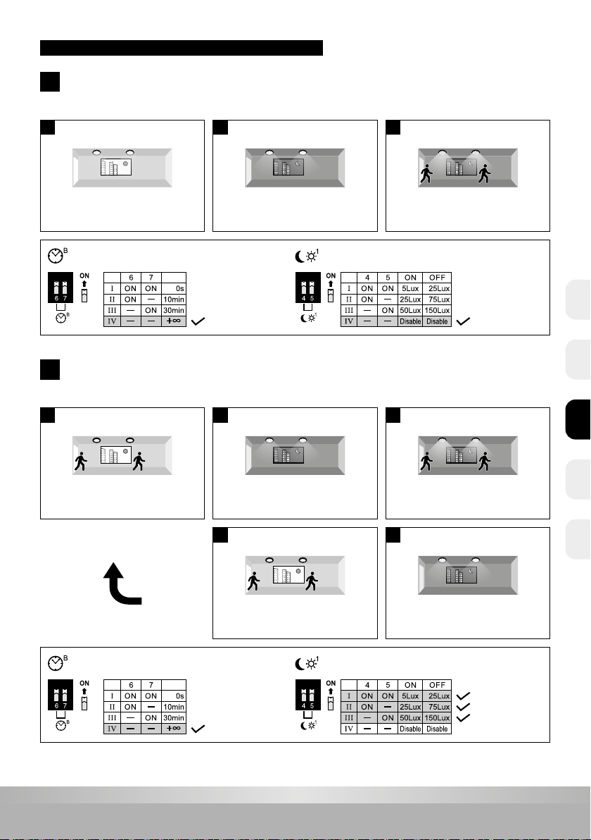
MICROWAVE SENSOR VOORBEELDEN VAN INSTELLINGEN
10% 10% 10% 10% 100% 100%
10% / 100%
0% / 10% op basis van daglicht / 100% bij beweging
C
1
1 2 3
D
Stand-by periode (gedimd licht)
Stand-by periode (gedimd licht)
Daglicht
Daglicht
Altijd aan op gedimd niveau --> na detectie 100% gedurende nalooptijd
Gedimd niveau aan/uit op basis van daglicht en 100% bij detectie
Overdag: gedimd niveau.
Uit bij voldoende daglicht,
ook na detectie.
‘S-avonds/‘s-nachts:
gedimd niveau.
10% 10%
2
5
‘S-avonds/‘s-nachts:
aan op gedimd niveau.
Uit bij voldoende daglicht,
ook na detectie.
100% gedurende nalooptijd,
bij detectie.
100% 100%
10% 10%
3
4
100% gedurende nalooptijd,
bij detectie.
‘S-avonds/‘s-nachts:
aan op gedimd niveau.
NL EN CZFR DE

6
www.prolumia.com
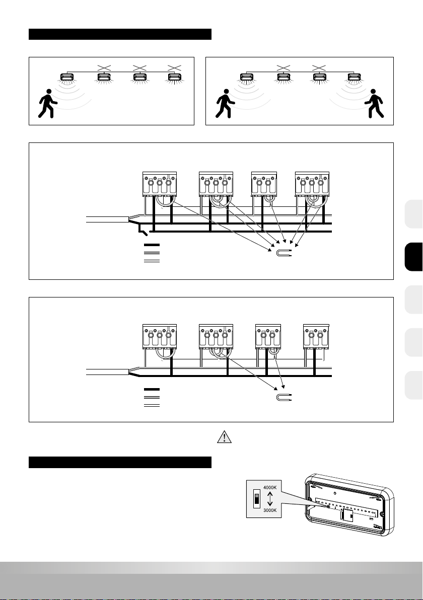
KEUZE LICHTKLEUR
U kunt het armatuur instellen op 2 verschillende lichtkleuren.
De schakelaar is te vinden op de LED module en is te zien
wanneer u de beschermingskap heeft verwijderd.
MASTER/SLAVE FUNCTIE
Functie A Functie B
Het aantal units in slave-functie is gelimiteerd. (Max. 30 stuks)
sensor sensor
sensor
sensor
sensor sensor sensor sensor
Functie A - Centraal geschakeld
Functie B - Alleen geschakeld d.m.v. ingebouwde sensoren
N 1 2N 1 2 3 N 1 2 3N 1 2 3
Met nood en
met sensor
Met nood en
zonder sensor
Zonder nood en
zonder sensor
Met nood en
zonder sensor
HOOFDAANSLUITING
Verwijder de korte kabel
Aan/uit of hoge/lage intensiteit
geregeld door sensor
N
L
Schakelaar t.b.v. eventueel centraal schakelen
N 1 2 3 N 1 2 N 1 2N 1 2 3
Met nood en
met sensor
Met nood en
zonder sensor
Zonder nood en
zonder sensor
Zonder nood en
met sensor
Verwijder de korte kabel
Aan/uit of hoge/lage intensiteit
geregeld door sensor
N
L
HOOFDAANSLUITING
NLENCZ FRDE

7
www.prolumia.com
Licht-
sterkte
KEUZE LICHTOPBRENGST
U kunt het armatuur instellen op 2 verschillende Lumen waarden:
ON - 100% (standaard)
1 - 50%
De schakelaar is te vinden naast de LED module en is te zien
wanneer u de beschermingskap heeft verwijderd.
MONTAGE
Rubber
Metaal
Draadbrug verwijderen bij externe schakeling
Continue spanning (i.v.m. noodfunctie)
N 1 2 3
HOOFDAANSLUITING
Draadbrug verwijderen bij externe schakeling
Continue spanning (i.v.m. noodfunctie)
N 1 2 3
HOOFDAANSLUITING
4Aansluiting kabel
Nood versie Nood + Sensor versie
(geschakelde fase niet verplicht)
1. Draai de afscherming los en open het LED paneel.
2. Haal het aansluitsnoer door de thule en xeer met de trekontlasting.
3. Bevestig het armatuur d.m.v. schroeven op de ondergrond.
(Let op de richting. Dit is aangegeven met de markering‘UP’op de basis van het armatuur.)
4. Sluit het aansluitsnoer correct aan op de terminal.
5. Sluit de stekker van de accu aan op de“Battery +/-” aansluiting van de noodunit.
6. Sluit het LED paneel en bevestig de afscherming.
N
L
N 1 2 3
L1A
L, N = Continue voeding
L = Geschakelde voeding
A = Controle noodfunctie
TESTEN
Test noodfunctie na de installatie.
NL EN CZFR DE

8
www.prolumia.com
Zachte doek
1 2 3
BINNENWERK VERVANGEN
Maak het armatuur eerst spanningsloos.
1. Maak de beschermkap los, verwijder daarna met een schroevendraaier de LED driver.
2. Haal de male-female-stekkers van elkaar en verwijder het oude binnenwerk.
3. Monteer het nieuwe binnenwerk en sluit vervolgens de male-female-stekkers stevig aan.
4. Bevestig de beschermkap.
ONDERHOUD
1. Maak het armatuur
spanningsloos.
2. Raak de LED’s niet aan tijdens
onderhoud of schoonmaak.
3. Gebruik geen chemische
schoonmaakmiddelen om de
lamp te reinigen.
BESCHERMING VAN HET MILIEU
Defecte elektrische apparaten behoren niet te worden weggegooid bij het huishoudelijk afval. Recycle waar mogelijk.
Neem contact op met uw gemeente of uw leverancier voor een deskundig recycling advies.
Vervangen
ACCU VERVANGEN
1. Maak het armatuur eerst spanningsloos.
2. Trek de plug van de accu uit de noodunit.
3. Verwijder de plastic bevestigingen.
4. Verwijder de oude accu.
5. Noteer de datum van ingebruikname van de accu.
6. Bevestig de nieuwe accu d.m.v. de plastic bevestigingen.
7. Sluit de stekker aan op de noodunit.
Hoofd-
aansluiting
NLENCZ FRDE
9
www.prolumia.com
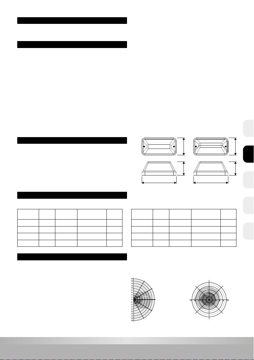
Walking speed: 0,3m/s
Ceiling mounting detection area (m)
Suggested installation height: 3m
Walking speed: 0,3m/s
Wall mounting detection area (m)
Suggested installation height: 2m
Standard version Semi shielded version
Art. no. Color Input
power Lumen
switchable Sensor
40010302 White 7W 700Lm / 350Lm -
40010312 Black 7W 700Lm / 350Lm -
40010303 White 8W 700Lm / 350Lm Yes
40010313 Black 8W 700Lm / 350Lm Yes
Art. no. Color Input
power Lumen
switchable Sensor
40010322 White 7W 500Lm / 250Lm -
40010332 Black 7W 500Lm / 250Lm -
40010323 White 8W 500Lm / 250Lm Yes
40010333 Black 8W 500Lm / 250Lm Yes
140110
280
140110
280
ATTENTION
CAUTION
TECHNICAL DATA
TECHNICAL INFORMATION
Please read the following instructions carefully to ensure that mounting operation will be carried out correctly.These instructions
should be properly preserved for future reference.
MICROWAVE SENSOR DESCRIPTION
Detection zone max. (d x h): 12m x 6m
Detection sensitivity: 50% or 100%, adjustable
Hold time: 5sec - 10min, adjustable
Daylight on: 5 - 50Lux, adjustable or disabled
Daylight o: 25 - 150Lux, adjustable or disabled
Stand-by period (low light level): 0 sec - +∞ min, adjustable
Stand-by dim level: 10% or 25%, adjustable
Ceiling mounting height: 6m max.
Motion detection (threshold): 0.3 ~ 3m/s
Detection angle: 150° (wall installation),
360° (ceiling installation)
Supply voltage: AC 220-240V 50/60Hz
Light source: SMD2835 LED
Batteries: Ni-Cd Duration: 1h
Operating temperature: -10°C - +50°C (Sensor version: upto max. +40°C)
Electrical safety class: Class II
1. The product must be installed by qualied technicians.The power supply must be cut before installation.
2. The installation wiring must be 2 x 1.0 mm² at least and wired in accordance with the latest IEE electrical regulations or the national requirements.
3. Cut the power supply before replacing battery.
4. Do not touch the electronic circuit and its components.
5. When xture is unable to maintain the 1 hour duration under battery operation, then the battery must be replaced.
6. Contact an authorised technical service center for the replacement of the battery and use only original manufacturer spare parts for any
other repairs.
7. Code for identication of battery production date: ex.1810 --- 2018, week10.
8. Do not touch the LEDs while installing or maintaining.
9. The LED light source of the lamp cannot be replaced. The complete product must be replaced if the light source is defect.
10. The charge of the battery will decrease by self-discharge if not connected to mains supply. Prolonged periods without voltage can damage the
battery. Battery warranty claims, as a result of such abuse, are specically EXCLUDED from warranty terms.
11. On many building sites, power circuits may be cut o in an uncontrolled and repetitive basis during construction. As a result, any unit on these
circuits, will have their batteries discharged or ‘cycled’. Excessive battery cycling will reduce through-life performance and may lead to premature
battery failure. Battery warranty claims, as a result of such abuse, are specically EXCLUDED from warranty terms.
NL EN CZFR DE

10
www.prolumia.com
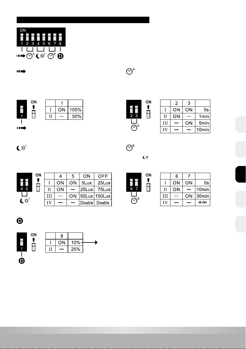
MICROWAVE SENSOR PARAMETER SETTINGS
Detection Area
This determines the eective range of the motion detector and is set
with DIP switches on the driver. Note that reducing the sensitivity will
also narrow the detection range.
Stand-by period
With the + ∞ setting, the xture will light up dimmed based on
the setting of and the amount of ambient light. With motion
detection, the light level goes to 100% during the hold time.
Hold Time
This determines the time the xture remains at 100% and is set with
DIP switches on the driver. The walk test (5s) setting is useful when
installing the xture to establish correct operation and range.
Stand-by Dim level
Adjustment of the luminous ux with dimmed light level.
When the DIP switch is set to +∞ on‘Stand-by period’,
the default setting is 10% and can’t be changed.
Daylight
With this setting it can be determined at what daylight level the
luminaire will or will not be switched on when motion is detected.
The photocell functionality can also be disabled.
NLENCZ FRDE
11
www.prolumia.com
MICROWAVE SENSOR EXAMPLES OF SETTINGS
100% 100%
100% 100%
100%10%/25%
0% / 100% / 10% or 25%
0% / 100%
A
B
1
1
2
2
3
3
4
Stand-by period (dimmed light)
Stand-by period (dimmed light)
Daylight
Daylight
O with sucient ambient light --> in the evening / at night after motion detection 100% during hold time
and 10% / 25% during stand-by time --> then o
O with sucient ambient light --> in the evening / at night after motion detection 100% during hold time --> then o
O with sucient daylight,
even after detection.
O with sucient daylight,
even after detection.
100% during hold time,
upon detection
and insucient daylight.
100% during hold time,
upon detection
and insucient daylight.
After hold time to 10%/25%
during stand-by time.
O after the end
of standby time.
O after hold time.
NL EN CZFR DE

12
www.prolumia.com
10% 10% 10% 10% 100% 100%
10% / 100%
0% / 10% based upon daylight / 100% when triggered
C
1
1 2 3
D
Stand-by period (dimmed light)
Stand-by period (dimmed light)
Daylight
Daylight
Always on at dimmed level --> after detection 100% during hold time
Dimmed level on/o based on daylight and 100% on detection
Daytime: dimmed level.
O with sucient daylight,
even after detection.
In the evening/at night:
dimmed level.
10% 10%
2
5
In the evening/at night:
on at dimmed level.
O with sucient daylight,
even after detection.
100% during hold time,
upon detection.
100% 100%
10% 10%
3
4
100% during hold time,
upon detection.
In the evening/at night:
on at dimmed level.
MICROWAVE SENSOR EXAMPLES OF SETTINGS
NLENCZ FRDE
13
www.prolumia.com
sensor sensor
sensor
sensor
sensor sensor sensor sensor
MASTER/SLAVE FUNCTION
Function A Function B
The number of slaves is limited. (Max. 30pcs)
SELECTABLE COLOR TEMPERATURE
There are 2 choices of color temperature by dierent setting on the
surface of the LED light engine.
The switch can be found on the LED module and can be seen
when you have removed the protective cap.
Function A - Central switched
Function B - Only switched by means of built-in sensors
N 1 2N 1 2 3 N 1 2 3N 1 2 3
With emergency
and with sensor
With emergency
and without sensor
Without emergency
and without sensor
With emergency
and without sensor
MAINS POWER SUPPLY
Remove the short cable
On/o or high/low intensity
controlled by sensor
N
L
Optional: switch for central switching
N 1 2 3 N 1 2 N 1 2N 1 2 3
With emergency
and with sensor
With emergency
and without sensor
Without emergency
and without sensor
Without emergency
and with sensor
Remove the short cable
On/o or high/low intensity
controlled by sensor
N
L
MAINS POWER SUPPLY
NL EN CZFR DE

14
www.prolumia.com
SELECTABLE OUTPUT BRIGHTNESS
There are two choices of output brightness by dierent setting on the surface of the LED light engine:
ON - 100% (standard)
1 - 50%
The switch can be found next to the LED module and can be
seen when you have removed the diuser.
Output
Brightness
Output
Brightness
4Cable connection
Remove wire bridge when externally switched
Uninterrupted mains supply (for emergency backup function)
N 1 2 3
MAINS POWER SUPPLY
Remove wire bridge when externally switched
Uninterrupted mains supply (for emergency backup function)
N 1 2 3
MAINS POWER SUPPLY
Emergency mode version Emergency mode + Sensor version
(switched phase not required)
Rubber
Metal
N
L
N 1 2 3
L1A
L, N = Un-switched line
L = Switched line
A = Test emergency operation
TESTING
Test emergency function after installation.
MOUNTING
1. Disassemble the diuser and LED panel.
2. Pull the power cord through the gasket.
3. Fix the xture on the surface with screws.
(Pay attention to the direction. This is indicated by the “UP”marking on the base of the xture.)
4. Connect the power cord on the terminal correctly.
5. Connect the plug of the battery rmly onto the emergency driver.
6. Assemble the LED panel and diuser.
NLENCZ FRDE

15
www.prolumia.com
Soft cloth
Mains
power
1 2 3
REPLACING THE LIGHT ENGINE
Cut o the mains power rst.
1. Open the diuser, then remove the LED light engine using tool.
2. Separate the male-female terminals, and remove the old light engine.
3. Assemble the new light engine, then connect the male-female terminals rmly.
4. Fix the diuser.
HOW TO REPLACE BATTERIES
1. Cut the power supply rst.
2. Pull out the plug of batteries from the emergency driver.
3. Screw out the plastic xers.
4. Remove the old batteries.
5. Record the date of commissioning of the batteries.
6. Fix the new batteries by plastic xers.
7. Connect the plug onto the emergency driver.
Replacing
MAINTENANCE
1. Cut o the mains power rst.
2. Don’t touch LED while
maintaining or cleaning.
3. Don’t use chemical reagent to
clean lamp.
ENVIRONMENTAL PROTECTION
Waste electrical products should not be disposed of with household waste. Please recycle where facilities exist.
Check with your local authority or retailer for recycling advice.
NL EN CZFR DE
16
www.prolumia.com
Lisez attentivement les instructions suivantes pour vous assurer que les travaux d’installation sont eectués correctement.
Conservez ces instructions en toute sécurité pour une utilisation future possible.
Tension d’alimentation: AC 220-240V 50/60Hz
Source de lumière: SMD2835 LED
Batterie: Ni-Cd Durée: 1 heure
Température de fonctionnement: -10°C - +50°C
(Version capteur: jusqu’à max. +40°C)
Classe de protection électrique: Classe II
1. Le produit doit être installé par des personnes qualiées. L’installation doit être mise hors tension avant l’installation.
2. Le câble d’installation doit avoir au moins 2 x 1,0 mm² et doit être raccordé conformément aux dernières réglementations électriques de l’IEE
ou selon les exigences nationales.
3. Débranchez l’alimentation avant de remplacer la batterie.
4. Ne touchez pas le circuit électronique et les composants.
5. Si l’autonomie de 1 heure n’est plus atteinte, la batterie doit être remplacée.
6. Contactez un centre de service technique reconnu pour remplacer la batterie et n’utilisez que des pièces d’origine pour d’autres réparations.
7. Code d’identication de la date de production de la batterie: ex.1810 --- 2018, semaine10.
8. Ne touchez pas les voyants pendant l’installation ou la maintenance.
9. La source de lumière LED de la lampe ne peut pas être remplacée. Le produit complet doit être remplacé si la source lumineuse
est défectueuse.
10. En se déchargeant automatiquement, la charge de la batterie, si elle n’est pas connectée au secteur, diminue lentement. Cela peut entraîner
des dommages à la batterie pendant une période de sans tension prolongée. Les dommages qui en résultent ne sont pas couverts
par la garantie.
11. Sur de nombreux sites de construction, les circuits de courant peuvent être interrompus de manière incontrôlée et répétitive pendant
la construction. En conséquence, les batteries peuvent se décharger. La charge et la décharge fréquente de la batterie réduiront sa durée
de vie et entraîneront une défaillance prématurée de la batterie. Les dommages qui en résultent ne sont pas couverts par la garantie.
Vitesse de mouvement: 0,3m/s
Portée de détection (m) montage mural
Hauteur de montage proposée: 2m
Vitesse de mouvement: 0,3m/s
Portée de détection (m) montage au plafond
Hauteur de montage proposée: 3m
ATTENTION
ATTENTION
DONNÉES TECHNIQUES
INFORMATIONS TECHNIQUES
CAPTEUR DE MICROONDES DESCRIPTION
Version standard Version semi-blindée
Plage de détection maxi (D x H): 12m x 6m
Sensibilité de détection: 50% ou 100%, réglable
Temps de combustion: 5sec - 10min, réglable
Lumière du jour: 5 - 50Lux, réglable ou désactivé
Lumière du jour désactivé: 25 - 150Lux, réglable ou désactivé
Période de stand-by (faible niveau de lumière):
0 sec - +∞, réglable
Niveau d’atténuation stand-by: 10% ou 25%, réglable
Hauteur de montage plafond: 6m max.
Détection de mouvement (seuil): 0,3 ~ 3m/s
Angle de détection: 150° (montage mural),
360° (montage au plafond)
Numéro
article
Couleur
Puissance Le ux lumineux
peut être
commuté Capteur
40010302 Blanc 7W 700Lm / 350Lm -
40010312 Noir 7W 700Lm / 350Lm -
40010303 Blanc 8W 700Lm / 350Lm Oui
40010313 Noir 8W 700Lm / 350Lm Oui
Numéro
article
Couleur
Puissance Le ux lumineux
peut être
commuté Capteur
40010322 Blanc 7W 500Lm / 250Lm -
40010332 Noir 7W 500Lm / 250Lm -
40010323 Blanc 8W 500Lm / 250Lm Oui
40010333 Noir 8W 500Lm / 250Lm Oui
140110
280
140110
280
NLENCZ FRDE
17
www.prolumia.com
CAPTEUR DE MICROONDES RÉGLAGE DES PARAMÈTRES
Plage de détection
Ceci détermine la portée eective du détecteur de mouvement et est
réglé avec les micro-interrupteurs sur le pilote. Rendez-vous compte
que réduire la sensibilité réduira également la plage de détection.
Période de stand-by
Avec le réglage + ∞, le luminaire s’allumera en atténuation en fonction
du réglage et de la quantité de lumière ambiante. Avec la
détection de mouvement, le niveau de lumière passe à 100% pendant
le temps de rodage.
Temps de rodage
Cela détermine le temps pendant lequel le luminaire reste allumé au
niveau de 100%. Cela peut être réglé avec des micro-interrupteurs
sur le pilote. Lors de l’installation du luminaire, le réglage du test de
marche (5s) est utile pour déterminer le fonctionnement et la portée
corrects.
Niveau d’atténuation stand-by
Réglage du ux lumineux avec un niveau de lumière atténuée.
Lorsque le commutateur DIP est réglé sur +∞ sur‘Période stand-by’,
le réglage par défaut est 10% et ne peut pas être modié.
Lumière de jour
Avec ce réglage, il est possible de déterminer à quel niveau de
lumière du jour le luminaire s’allumera ou ne sera pas allumé
lorsqu’un mouvement est détecté. La fonctionnalité photocellule peut
également être désactivée.
NL EN CZFR DE
18
www.prolumia.com
CAPTEUR MICROWAVE EXEMPLES DE PARAMETRES
100% 100%
100% 100%
100%10%/25%
0% / 100% / 10% ou 25%
0% / 100%
A
B
1
1
2
2
3
3
4
Période de stand-by(lumière atténuée)
Période de stand-by(lumière atténuée)
Lumiere de jour
Lumiere de jour
Éteint en cas de lumière ambiante susante -> soir / nuit après détection de mouvement 100% pendant le temps de rodage
et 10% / 25% pendant le temps de stand-by -> puis éteint
Éteint en cas de lumière ambiante susante -> soir / nuit après détection de mouvement 100% pendant le temps de rodage ->
puis éteint
Éteint en cas de lumière du jour
susante, même après détection.
Éteint en cas de lumière du jour susante,
même après détection.
100% pendant le temps de rodage,
en cas de détection et de lumière
du jour insusante.
100% pendant le temps de rodage, en cas de
détection et de lumière du jour insusante.
Après le temps de rodage
à 10% / 25% pendant le temps
de stand-by.
Éteint après temps
de stand-by.
Éteint après le temps
de rodage.
NLENCZ FRDE
19
www.prolumia.com
CAPTEUR MICROWAVE EXEMPLES DE PARAMETRES
10% 10% 10% 10% 100% 100%
10% / 100%
0% / 10% en fonction de la lumière du jour / 100% en fonction du mouvement
C
1
1 2 3
D
Période de stand-by(lumière atténuée)
Période de stand-by(lumière atténuée)
Lumiere de jour
Lumiere de jour
Toujours activé sur un niveau atténué --> après détection 100% pendant le temps de rodage
Niveau atténué marche / arrêt basé sur la lumière du jour et 100% en cas de la détection
Pendant la journée: niveau atténué.
Éteint en cas de susamment de lumière du jour,
même après détection.
Soir / Nuit: niveau atténué.
10% 10%
2
5
Le soir/la nuit: activé a niveau atténué.
Éteint en cas de susamment de lumière du jour,
même après détection.
100% pendant le temps de rodage,
en cas de détection.
100% 100%
10% 10%
3
4
100% pendant le temps de rodage,
en cas de détection.
Le soir/la nuit: activé a niveau atténué.
NL EN CZFR DE

20
www.prolumia.com
CHOIX DE LA TEMPÉRATURE DE COULEUR
Vous pouvez régler le luminaire sur 2 températures de couleur diérentes.
L’interrupteur se trouve à côté du module LED et peut être vu lorsque
vous avez retiré le capuchon de protection.
capteur capteur capteur capteur
capteur capteur capteur capteur
FONCTION MAÎTRE / ESCLAVE
Fonction A Fonction B
Le nombre d’unités dans la fonction esclave est limité. (Max 30 pièces)
N 1 2N 1 2 3 N 1 2 3N 1 2 3
Avec urgence et
avec capteur
Avec urgence et
sans capteur
Sans urgence et
sans capteur
Avec urgence et
sans capteur
CONNEXION PRINCIPALE
Retirez le cable court
On/o ou haute/basse intensité
contrôlée par le capteur
N
L
Commutateur pour une éventuelle commutation centraliséeCommutateur pour une éventuelle commutation centralisée
N 1 2 3 N 1 2 N 1 2N 1 2 3
Avec urgence et
avec capteur
Avec urgence et
sans capteur
Sans urgence et
sans capteur
Sans urgence et
avec capteur
Retirez le cable court
On/o ou haute/basse intensité
contrôlée par le capteur
N
L
CONNEXION PRINCIPALE
Fonction A - Commutation centralisée
Fonction B - Seulement commuté au moyen de capteurs intégrés
NLENCZ FRDE
This manual suits for next models
11
Table of contents
Languages:
Other PROLUMIA Lighting Equipment manuals

PROLUMIA
PROLUMIA LED PRO-AQUA III User manual

PROLUMIA
PROLUMIA PRO-SIGN User manual

PROLUMIA
PROLUMIA Prodisc III + Emergency mode User manual

PROLUMIA
PROLUMIA ECODISC II MAXI User manual

PROLUMIA
PROLUMIA LUMIAFLEX 1004 User manual

PROLUMIA
PROLUMIA ROCKDISC III User manual

PROLUMIA
PROLUMIA PRO-PORTAL 40010021 User manual


