PROLUMIA PRO-PORTAL 40010021 User manual

www.prolumia.com
PROPORTAL
40010021 Pro-Portal + Emergency mode
40010031 Pro-Portal + Microwave sensor + Emergency mode
+ EMERGENCY MODE
OPERATING INSTRUCTION
GEBRUIKSAANWIJZING
MANUEL D’UTILISATION
INSTALAČNÍ NÁVOD
GEBRAUCHSANLEITUNG

2
www.prolumia.com
Detectiebereik wandmontage (Eenheid: m)
Voorgestelde montagehoogte: 1 - 1,8m
Detectiebereik plafondmontage (Eenheid: m)
Voorgestelde montagehoogte: 2,5 - 6m
ATTENTIE
OPGELET
TECHNISCHE DATA
TECHNISCHE INFORMATIE
1. Het product dient te worden geïnstalleerd door gekwaliceerde personen. De installatie dient, voorafgaand aan de montage, spanningsloos
te worden gemaakt.
2. De installatiedraad moet minimaal 2 x 1,0 mm² zijn en worden aangesloten in overeenstemming met de laatste elektriciteitsvoorschriften van
IEE of volgens de nationale eisen.
3. Sluit de stroomtoevoer van de voeding af voordat u de accu vervangt.
4. Raak het elektronische circuit en de componenten niet aan.
5. Indien de autonomie van 1 uur niet meer wordt gehaald, dient de accu vervangen te worden.
6. Neem contact op met een erkende technische service center voor het vervangen van de accu en gebruik alleen originele onderdelen voor
andere reparaties.
7. Identicatie code van de accu productiedatum: ex.1810 --- 2018, week10.
8. Raak de LED’s niet aan tijdens installatie of onderhoud.
9. Dit product bevat een lichtbron van energie-eciëntieklasse D.
10. Door zelfontlading neemt de lading van de accu, als deze niet op het net is aangesloten, langzaam af. Dit kan leiden tot schade aan de accu bij
langdurige spanningsloosheid. De hierdoor ontstane schade valt niet onder garantie.
11. Op veel bouwplaatsen kunnen stroomcircuits worden onderbroken op een ongecontroleerde en repetitieve basis tijdens de bouw. Accu’s
kunnen als gevolg hiervan leeglopen. Het frequent laden en ontladen van de accu zal de levensduur verkorten en kan leiden tot voortijdig
falen van de accu. De hierdoor ontstane schade valt niet onder garantie.
Voedingsspanning: AC 220-240V 50/60Hz
Lichtbron: LED SMD2835
Accu: Ni-Cd Duur: 1 uur
Bedrijfstemperatuur: -20°C - +50°C
Elektrische veiligheidsklasse: Klasse II
Artikelnr. Type LED Vermogen Lichtstroom
schakelbaar Lichtstroom
noodbedrijf Sensor Werking Duur Accu
40010021 SMD2835 7,5W 600Lm / 300Lm 200Lm - (Niet-)permanent
(schakelbaar) 1 uur Ni-CD 2/3AA450mAhHT 7.2V
40010031 SMD2835 8,5W 600Lm / 300Lm 200Lm Ja (Niet-)permanent
(schakelbaar) 1 uur Ni-CD 2/3AA450mAhHT 7.2V
Lees de volgende instructies zorgvuldig door om ervoor te zorgen dat de montagewerkzaamheden op de juiste manier
worden uitgevoerd. Bewaar deze instructies goed voor eventueel toekomstig gebruik.
MICROWAVE SENSOR BESCHRIJVING
Detectiebereik max. (D x H): 14m x 6m
Detectie-gevoeligheid: 25% - 100%, instelbaar
Brandduur: 5sec - 30min, instelbaar
Daglicht 1: 5 - 15Lux, instelbaar of uitschakelen
Daglicht 2: 35 - 150Lux, instelbaar of uitschakelen
(bij daglichtprioriteit)
Nalooptijd: 5 - 30sec - 1 - 5 - 15 - 30min (instelbaar)
Nalooptijd oriëntatieverlichting:
0 - 10 - 20 - 30 - 60 - ∞ min (instelbaar)
Montagehoogte: 6m max.
Bewegingsdetectie: 0,5 ~ 3m/s
Detectiehoek: 150° (wandmontage),
360° (plafondmontage)
NLENCZ FRDE

3
www.prolumia.com
Detectiebereik
Dit bepaalt het eectieve bereik van de bewegingsmelder en wordt
met de micro-schakelaars op de sensor ingesteld, zie guur onder.
Wees er van bewust dat het verminderen van de gevoeligheid ook het
detectiebereik zal verkleinen.
Nalooptijd oriëntatieverlichting
Gedurende deze periode zal het armatuur op laag niveau (20%)
branden. Wanneer deze is ingesteld op +∞ geeft het armatuur
permanent 20% licht als er geen beweging gedetecteerd wordt. Dit
wordt ingesteld met micro-schakelaars op de sensor, zie guur onder.
Daglicht 2
Dit is alleen van toepassing onder modus 2.
Het verwijst naar het daglichtniveau waaronder het armatuur op laag
niveau gaat branden.
Nalooptijd
Dit bepaalt de tijd dat het armatuur op 100% niveau blijft branden. Dit
kan worden ingesteld met micro-schakelaars op de sensor, zie guur
onder. Tijdens het installeren van het armatuur is de looptest-instelling
(5s) handig om de juiste werking en het bereik vast te stellen.
Mode
Modus 1: Armatuur blijft uit bij bewegingsdetectie indien het
daglichtniveau boven de bij“Daglicht 1” ingestelde waarde ligt.
Modus 2: Indien het daglichtniveau onder de bij“Daglicht 2”
ingestelde waarde komt, zal het armatuur op laag niveau gaan
branden. Bij bewegingsdetectie wordt opgeschakeld naar 100%.
Daglicht 1
Hiermee kan de sensor het armatuur inschakelen wanneer het
omgevingslicht volledig daglicht (15Lux), weinig daglicht (10Lux) of
donker (5Lux) is. Ook kan de sensor hiermee worden uitgeschakeld.
Dit wordt ingesteld met micro-schakelaars op de sensor, zie guur
onder. Zolang het lichtniveau boven de ingestelde waarde ligt, zal het
armatuur bij bewegingsdetectie uitblijven.
MICROWAVE SENSOR INSTELLING PARAMETERS
NL EN CZFR DE

4
www.prolumia.com
100% 100%
100%20%
20% 20% 20% 20%
100% 100%
100% 100%
20% 20%
100% 100%
Modus Nalooptijd
Modus Nalooptijd
Modus Nalooptijd
MICROWAVE SENSOR INSTELLING PARAMETERS
0% / 100% / 20%
20% / 100%
0% / 100%
0% / 20% op basis van daglicht /
100% bij beweging
A
C
B
D
Modus
KEUZE LICHTKLEUR
U kunt het armatuur instellen op 2 verschillende lichtkleuren.
De schakelaar is te vinden op de LED module en is te zien
wanneer u de beschermingskap heeft verwijderd.
NLENCZ FRDE

5
www.prolumia.com
sensor sensor sensor sensor
Sensor Sensor Sensor Sensor
MASTER/SLAVE FUNCTIE
Functie A
Functie A - Centraal geschakeld
Functie B - Alleen geschakeld d.m.v. ingebouwde sensoren
Functie B
Het aantal units in slave-functie is gelimiteerd. (Max. 60 stuks)
N 1 2N 1 2 3 N 1 2 3N 1 2 3
Met nood en
met sensor
4001003x
Met nood en
zonder sensor
4001002x
Zonder nood en
zonder sensor
4001000x
Met nood en
zonder sensor
4001002x
HOOFDAANSLUITING
Verwijder de korte kabel
Aan/uit of hoge/lage intensiteit
geregeld door sensor
N
L
Schakelaar t.b.v. eventueel centraal schakelen
N 1 2 3 N 1 2 N 1 2N 1 2 3
Met nood en
met sensor
4001003x
Met nood en
zonder sensor
4001002x
Zonder nood en
zonder sensor
4001000x
Zonder nood en
met sensor
4001001x
Verwijder de korte kabel
Aan/uit of hoge/lage intensiteit
geregeld door sensor
N
L
HOOFDAANSLUITING
Licht-
sterkte
KEUZE LICHTOPBRENGST
U kunt het armatuur instellen op 2 verschillende Lumen waarden:
ON - 600Lm (standaard)
1 - 300Lm
De schakelaar is te vinden naast de LED module en is te zien
wanneer u de beschermingskap heeft verwijderd.
NL EN CZFR DE

6
www.prolumia.com
Draadbrug verwijderen bij externe schakeling
Continue spanning (i.v.m. noodfunctie)
N 1 2 3
HOOFDAANSLUITING
Draadbrug verwijderen bij externe schakeling
Continue spanning (i.v.m. noodfunctie)
N 1 2 3
HOOFDAANSLUITING
4Aansluiting kabel
N
L
N 1 2 3
L1A
Rubber
Metaal
PG13.5/M20
ACCESSOIRES NOODUITGANG SYMBOLEN
40010040
Nooduitgang
Omhoog
40010041
Nooduitgang
Omlaag
40010042
Nooduitgang
Links
40010043
Nooduitgang
Rechts
MONTAGE
TESTEN
1. Draai de afscherming los en open het LED paneel.
2. Haal het aansluitsnoer door de thule en xeer met de trekontlasting.
3. Bevestig het armatuur d.m.v. schroeven op de ondergrond.
4. Sluit het aansluitsnoer correct aan op de terminal.
5. Sluit de stekker van de accu aan op de“Battery +/-” aansluiting van de noodunit.
6. Sluit het LED paneel en bevestig de afscherming.
L, N = Continue voeding
L = Geschakelde voeding
A = Controle noodfunctie
Test noodfunctie na de installatie.
Nood versie Nood + Sensor versie
(geschakelde fase niet verplicht)
NLENCZ FRDE

7
www.prolumia.com
Zachte doek
Hoofd-
aansluiting
ON
OFF
Vervangen
Replacing
1 2 3
BINNENWERK VERVANGEN
Maak het armatuur eerst spanningsloos.
1. Maak de beschermkap los, verwijder daarna met een schroevendraaier de LED driver.
2. Haal de male-female-stekkers van elkaar en verwijder het oude binnenwerk.
3. Monteer het nieuwe binnenwerk en sluit vervolgens de male-female-stekkers stevig aan.
4. Bevestig de beschermkap.
ONDERHOUD
1. Maak het armatuur
spanningsloos.
2. Raak de LED’s niet aan tijdens
onderhoud of schoonmaak.
3. Gebruik geen chemische
schoonmaakmiddelen om de
lamp te reinigen.
BESCHERMING VAN HET MILIEU
Defecte elektrische apparaten behoren niet te worden weggegooid bij het huishoudelijk afval. Recycle waar mogelijk.
Neem contact op met uw gemeente of uw leverancier voor een deskundig recycling advies.
ACCU VERVANGEN
1. Maak het armatuur eerst spanningsloos.
2. Trek de plug van de accu uit de noodunit.
3. Verwijder de plastic bevestigingen.
4. Verwijder de oude accu.
5. Bevestig de nieuwe accu d.m.v. de plastic bevestigingen.
6. Sluit de stekker aan op de noodunit.
7. Noteer de datum van ingebruikname van de accu.
NL EN CZFR DE

8
www.prolumia.com
Wall mounting detection area (Unit: m)
Suggested installation height: 1 - 1.8m
Ceiling mounting detection area (Unit: m)
Suggested installation height: 2.5 - 6m
Art.no. LED type Input
power Lumen
switchable Lumen Emer-
gency mode Sensor Mode of
operation Duration Battery
40010021 SMD2835 7.5W 600Lm / 300Lm 200Lm - (Non) maintained
(switchable) 1h Ni-CD 2/3AA450mAhHT 7.2V
40010031 SMD2835 8.5W 600Lm / 300Lm 200Lm Yes (Non) maintained
(switchable) 1h Ni-CD 2/3AA450mAhHT 7.2V
ATTENTION
CAUTION
TECHNICAL DATA
TECHNICAL INFORMATION
1. The product must be installed by qualied technicians.The power supply must be cut before installation.
2. The installation wiring must be 2 x 1.0 mm² at least and wired in accordance with the latest IEE electrical regulations or the national requirements.
3. Cut the power supply before replacing battery.
4. Do not touch the electronic circuit and its components.
5. When xture is unable to maintain the 1 hour duration under battery operation, then the battery must be replaced.
6. Contact an authorised technical service center for the replacement of the battery and use only original manufacturer spare parts for any other
repairs.
7. Code for identication of battery production date: ex.1810 --- 2018, week10.
8. Do not touch the LEDs while installing or maintaining.
9. This product contains a light source of energy eciency class D.
10. The charge of the battery will decrease by self-discharge if not connected to mains supply. Prolonged periods without voltage can damage the
battery. Battery warranty claims, as a result of such abuse, are specically EXCLUDED from warranty terms.
11. On many building sites, power circuits may be cut o in an uncontrolled and repetitive basis during construction. As a result, any unit on these
circuits, will have their batteries discharged or ‘cycled’. Excessive battery cycling will reduce through-life performance and may lead to premature
battery failure. Battery warranty claims, as a result of such abuse, are specically EXCLUDED from warranty terms.
Supply voltage: AC 220-240V 50/60Hz
Light source: LED SMD2835
Batteries: Ni-Cd Duration: 1h
Operating temperature: -20°C - +50°C
Electrical safety class: Class II
Please read the following instructions carefully to ensure that mounting operation will be carried out correctly.These instructions
should be properly preserved for future reference.
MICROWAVE SENSOR DESCRIPTION
Detection zone max. (d x h): 14m x 6m
Detection sensitivity: 25% - 100%, adjustable
Hold time: 5sec - 30min, adjustable
Daylight 1: 5 - 15Lux, adjustable or disable
Daylight 2: 35 - 150Lux, adjustable or disable
(with daylight priority)
Hold time: 5 - 30sec - 1 - 5 - 15 - 30min (adjustable)
Hold time orientation lighting:
0 - 10 - 20 - 30 - 60 - ∞ min (adjustable)
Mounting height: 6m max.
Motion detection: 0.5 ~ 3m/s
Detection angle: 150° (wall installation),
360° (ceiling installation)
NLENCZ FRDE

9
www.prolumia.com
MICROWAVE SENSOR PARAMETER SETTINGS
Detection Area
This determines the eective range of the motion detector and is set
with DIP switches on the sensor, please see gure below. Note that
reducing the sensitivity will also narrow the detection range.
Hold time orientation lighting
During this period, the xture will light up at low level (20%). When
this is set to +∞, the xture gives permanent 20% light when no
movement detected. It is set with DIP switches on the sensor, please
see gure below.
Daylight 2
This is only applicable under mode 2.
Under this daylight level the xture will light at low level.
Hold Time
This determines the time the xture remains at 100% and is set with
DIP switches on the sensor, please see gure below. The walk test
(5s) setting is useful when installing the xture to establish correct
operation and range.
Mode
Mode 1: Fixture remains o during motion if the daylight level is
above the value set at“Daylight 1”.
Mode 2: When the daylight level falls below the value set under
“Daylight 2”, the xture will light at low level. When motion is detected,
it is shifting to 100%.
Daylight 1
This allows the sensor to switch the unit on when daylight level is
either full daylight (15Lux), low daylight (10Lux),or after dark (5Lux). It
also allows the sensor to be disabled. As long as the light level is above
the set point, the xture will stay o when motion is detected.
NL EN CZFR DE

10
www.prolumia.com
100% 100%
100%20%
20% 20% 20% 20%
100% 100%
100% 100%
20% 20%
100% 100%
Mode Hold time
Mode Hold time
Mode Hold time
MICROWAVE SENSOR PARAMETER SETTINGS
0% / 100% / 20%
20% / 100%
0% / 100%
0% / 20% based upon daylight /
100% when triggered
A
C
B
D
Mode
OPTIONAL COLOR TEMPERATURE
There are 2 choices of color temperature by dierent setting on the
surface of the LED light engine.
The switch can be found on the LED module and can be seen
when you have removed the protective cap.
NLENCZ FRDE

11
www.prolumia.com
Output
Brightness
OPTIONAL OUTPUT BRIGHTNESS
There are two choices of output brightness by dierent setting on the surface of the LED light engine:
ON - 600Lm (standard)
1 - 300Lm
The switch can be found next to the LED module and can be
seen when you have removed the protective cap.
sensor sensor sensor sensor
Sensor Sensor Sensor Sensor
MASTER/SLAVE FUNCTION
Function A Function B
The number of slaves is limited. (Max. 60pcs)
Function A - Central switched
Function B - Only switched by means of built-in sensors
N 1 2N 1 2 3 N 1 2 3N 1 2 3
With emergency
and with sensor
4001003x
With emergency
and without sensor
4001002x
Without emergency
and without sensor
4001000x
With emergency
and without sensor
4001002x
MAINS POWER SUPPLY
Remove the short cable
On/o or high/low intensity
controlled by sensor
N
L
Optional: switch for central switching
N 1 2 3 N 1 2 N 1 2N 1 2 3
With emergency
and with sensor
4001003x
With emergency
and without sensor
4001002x
Without emergency
and without sensor
4001000x
Without emergency
and with sensor
4001001x
Remove the short cable
On/o or high/low intensity
controlled by sensor
N
L
MAINS POWER SUPPLY
NL EN CZFR DE

12
www.prolumia.com
N
L
N 1 2 3
L1A
4Cable connection
Rubber
Metal
PG13.5/M20
L, N = Un-switched line
L = Switched line
A = Test emergency operation
Remove wire bridge when externally switched
Uninterrupted mains supply (for emergency backup function)
N 1 2 3
MAINS POWER SUPPLY
Remove wire bridge when externally switched
Uninterrupted mains supply (for emergency backup function)
N 1 2 3
MAINS POWER SUPPLY
ACCESSORIES EXIT SIGNS
40010040
Exit sign
Up
40010041
Exit sign
Down
40010042
Exit sign
Left
40010043
Exit sign
Right
MOUNTING
TESTING
1. Disassemble the diuser and LED panel.
2. Pull the power cord through the gasket.
3. Fix the xture on the surface with screws.
4. Connect the power cord on the terminal correctly.
5. Connect the plug of the battery rmly onto the emergency driver.
6. Assemble the LED panel and diuser.
Emergency mode version Emergency mode + Sensor version
(switched phase not required)
Test emergency function after installation.
NLENCZ FRDE

13
www.prolumia.com
Soft cloth
Replacing
Replacing
Mains
power
ON
OFF
1 2 3
REPLACING THE LIGHT ENGINE
Cut o the mains power rst.
1. Open the diuser, then remove the LED light engine using tool.
2. Separate the male-female terminals, and remove the old light engine.
3. Assemble the new light engine, then connect the male-female terminals rmly.
4. Fix the diuser.
MAINTENANCE
1. Cut o the mains power rst.
2. Don’t touch LED while
maintaining or cleaning.
3. Don’t use chemical reagent to
clean lamp.
ENVIRONMENTAL PROTECTION
Waste electrical products should not be disposed of with household waste. Please recycle where facilities exist.
Check with your local authority or retailer for recycling advice.
HOW TO REPLACE BATTERIES
1. Cut the power supply rst.
2. Pull out the plug of batteries from the emergency driver.
3. Screw out the plastic xers.
4. Remove the old batteries.
5. Fix the new batteries by plastic xers.
6. Connect the plug onto the emergency driver.
7. Record the date of commissioning of the batteries.
NL EN CZFR DE

14
www.prolumia.com
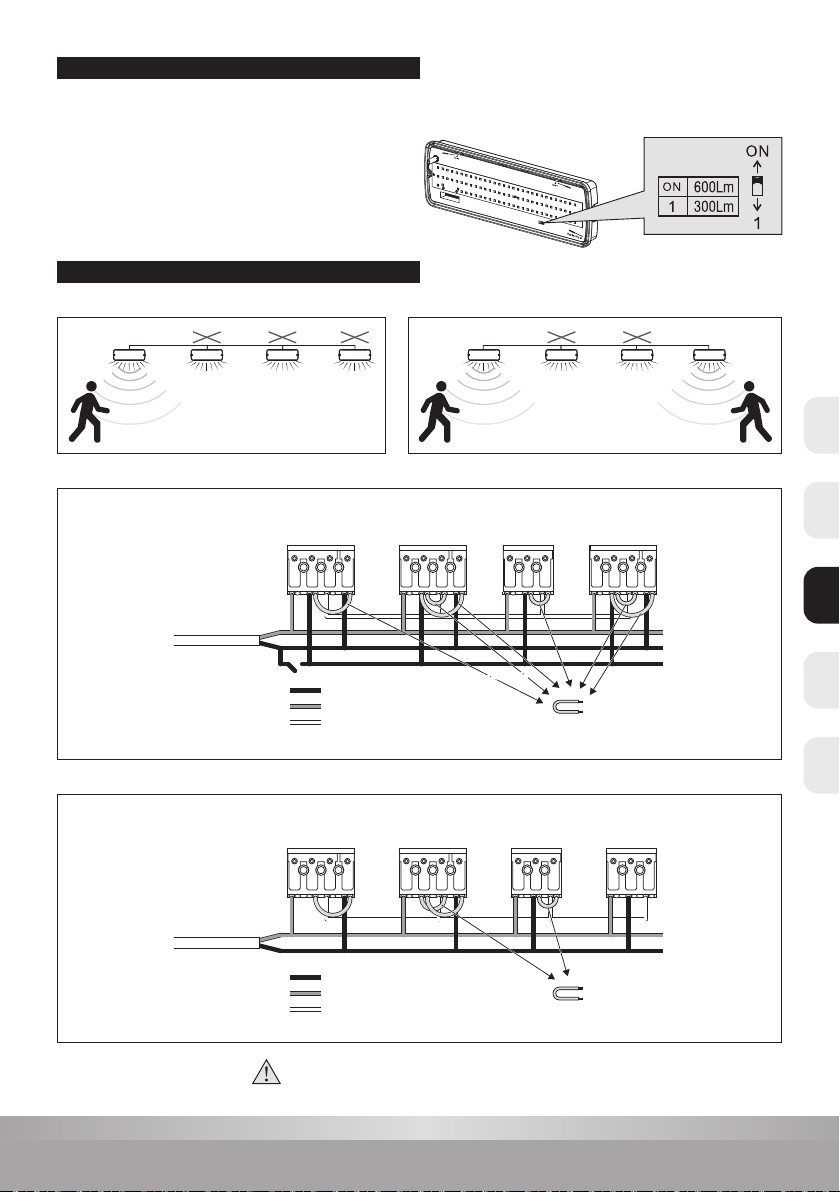
Portée de détection montage mural (Unité: m)
Hauteur de montage proposée: 1 - 1,8m
Portée de détection montage au plafond (Unité: m)
Hauteur de montage proposée: 2,5 - 6m
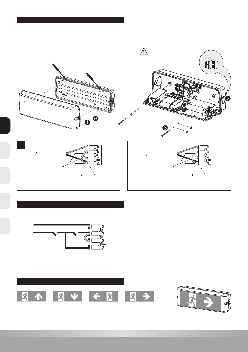
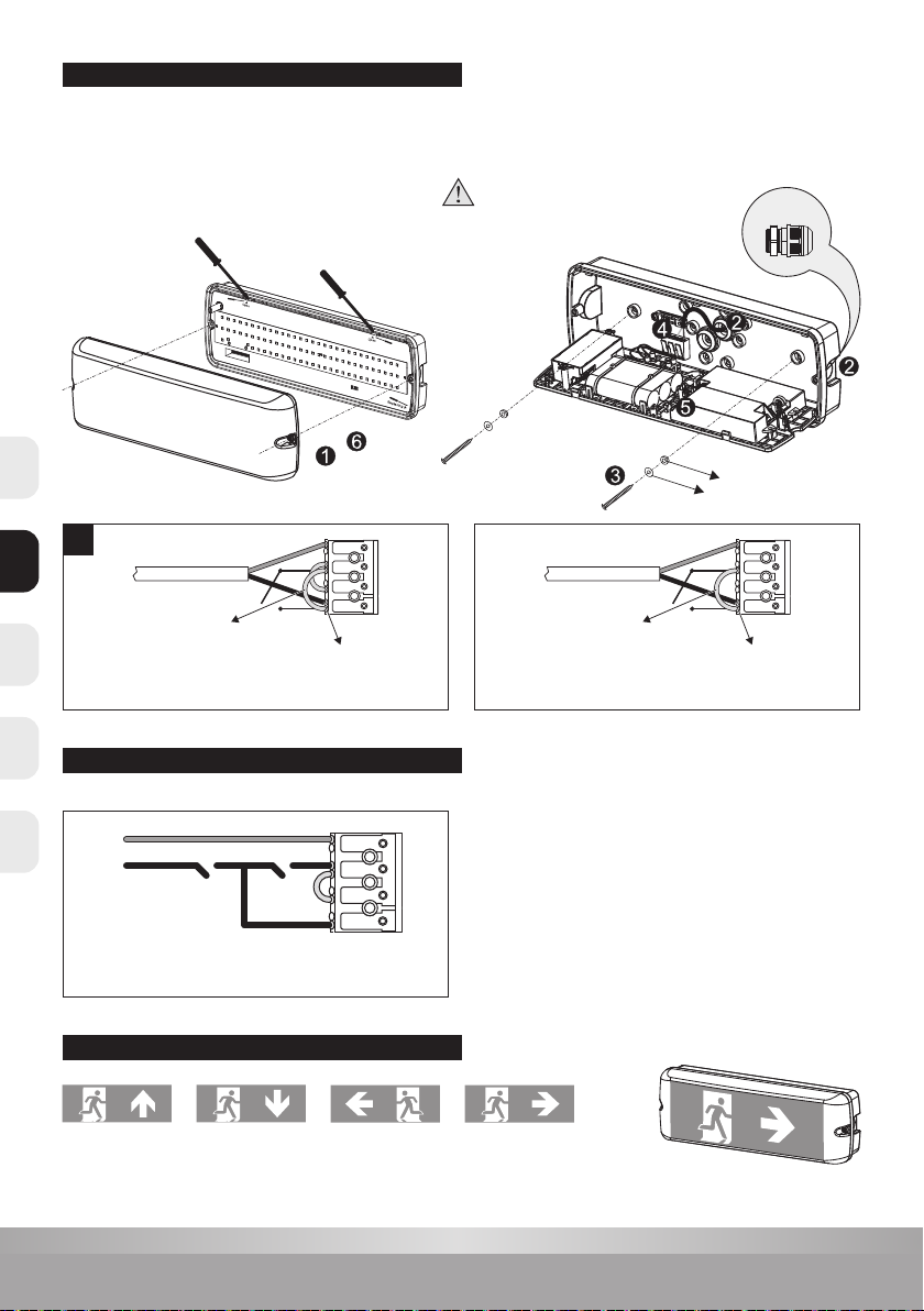
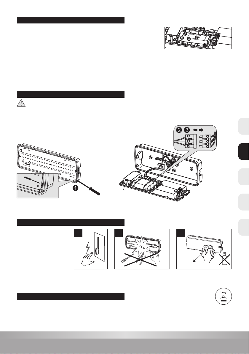
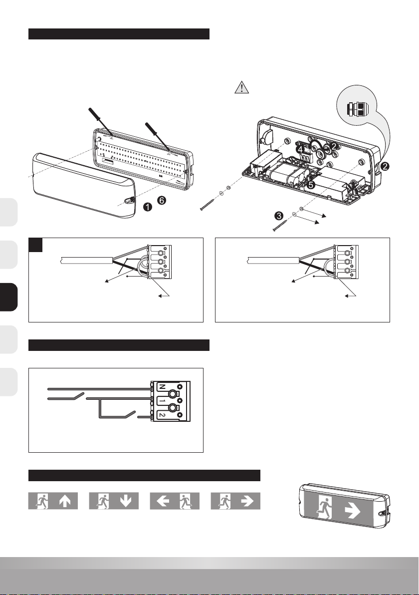
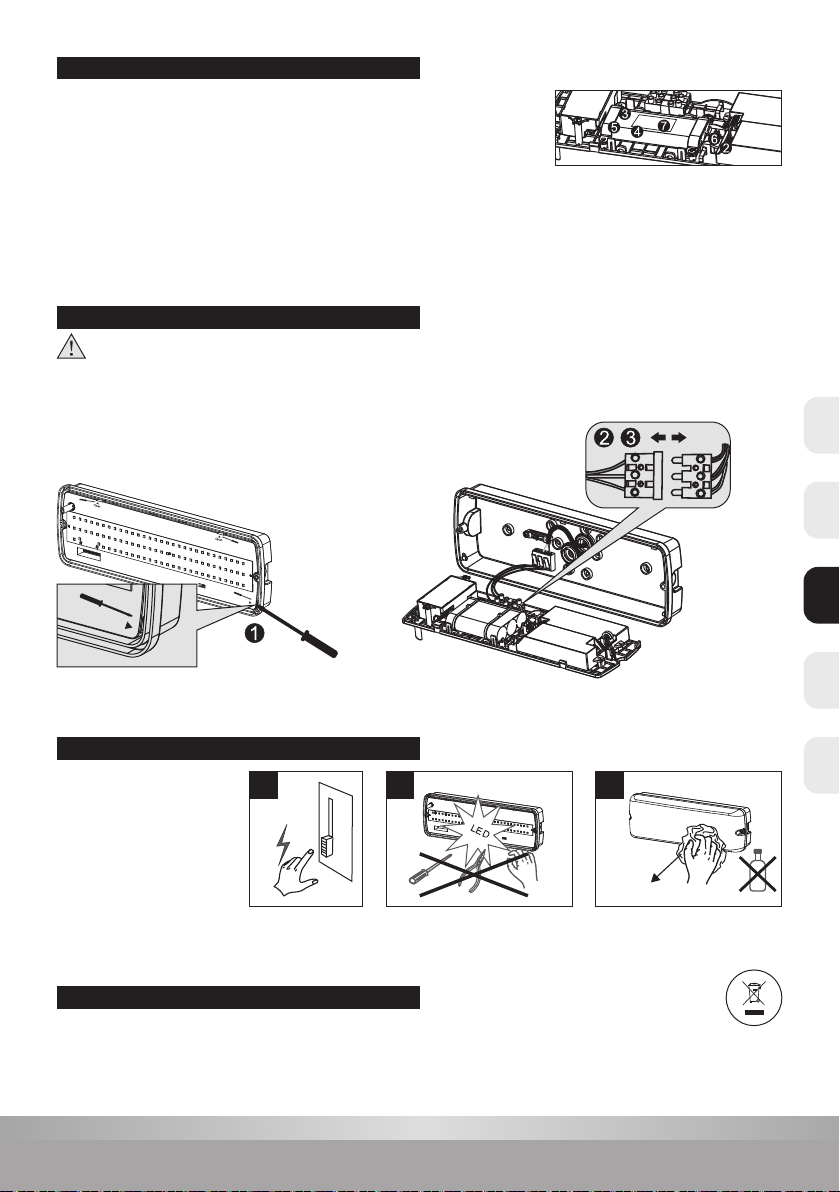
1. Le produit doit être installé par des personnes qualiées. L’installation doit être mise hors tension avant l’installation.
2. Le câble d’installation doit avoir au moins 2 x 1,0 mm² et doit être raccordé conformément aux dernières réglementations électriques de l’IEE
ou selon les exigences nationales.
3. Débranchez l’alimentation avant de remplacer la batterie.
4. Ne touchez pas le circuit électronique et les composants.
5. Si l’autonomie de 1 heure n’est plus atteinte, la batterie doit être remplacée.
6. Contactez un centre de service technique reconnu pour remplacer la batterie et n’utilisez que des pièces d’origine pour d’autres réparations.
7. Code d’identication de la date de production de la batterie: ex.1810 --- 2018, semaine10.
8. Ne touchez pas les voyants pendant l’installation ou la maintenance.
9. Ce produit contient une source lumineuse de classe d’ecacité énergétique D.
10. En se déchargeant automatiquement, la charge de la batterie, si elle n’est pas connectée au secteur, diminue lentement. Cela peut entraîner
des dommages à la batterie pendant une période de sans tension prolongée. Les dommages qui en résultent ne sont pas couverts
par la garantie.
11. Sur de nombreux sites de construction, les circuits de courant peuvent être interrompus de manière incontrôlée et répétitive pendant
la construction. En conséquence, les batteries peuvent se décharger. La charge et la décharge fréquente de la batterie réduiront sa durée
de vie et entraîneront une défaillance prématurée de la batterie. Les dommages qui en résultent ne sont pas couverts par la garantie.
Tension d’alimentation: AC 220-240V 50/60Hz
Source de lumière: LED SMD2835
Batterie: Ni-Cd Durée: 1 heure
Température de fonctionnement: -20°C - +50°C
Classe de protection électrique: Classe II
Numéro
article Type LED Puissance Le ux
lumineux peut
être commuté
Fonctionnement
d’urgence du
ux lumineux Capteur Fonctionne-
ment Cher Batterie
40010021
SMD2835 7,5W 600Lm / 300Lm 200Lm - (Non-) permanent
(commutable) 1 heure Ni-CD 2/3AA450mAhHT 7.2V
40010031
SMD2835 8,5W 600Lm / 300Lm 200Lm Oui (Non-) permanent
(commutable) 1 heure Ni-CD 2/3AA450mAhHT 7.2V
Lisez attentivement les instructions suivantes pour vous assurer que les travaux d’installation sont eectués correctement.
Conservez ces instructions en toute sécurité pour une utilisation future possible.
ATTENTION
ATTENTION
DONNÉES TECHNIQUES
INFORMATIONS TECHNIQUES
CAPTEUR DE MICROONDES DESCRIPTION
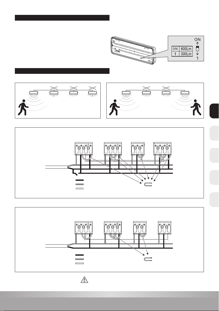
Plage de détection maxi (D x H): 14m x 6m
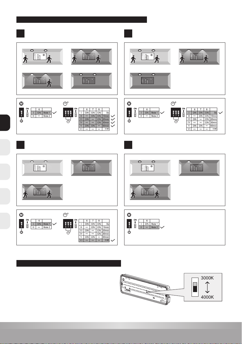
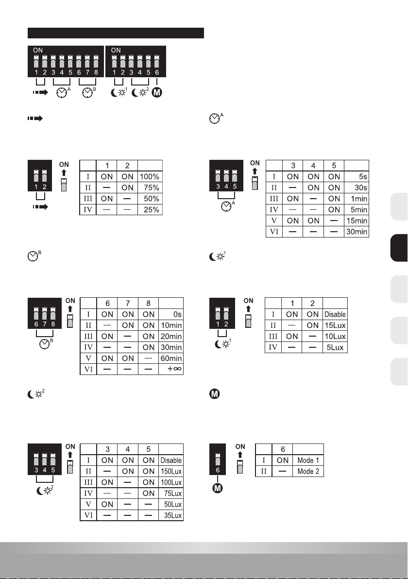
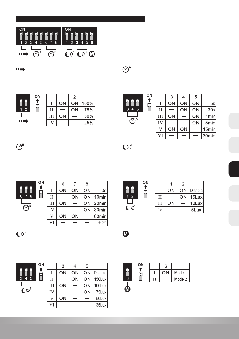
Sensibilité de détection: 25% - 100%, réglable
Temps de combustion: 5sec - 30min, réglable
Lumière du jour 1: 5 - 15Lux, réglable ou désactiver
Lumière du jour 2: 35 - 150Lux, réglable ou
désactiver (en priorité jour)
Temps de suivi: 5 - 30sec - 1 - 5 - 15 - 30min
(réglable)
Temps de suivi lumière d’orientation:
0 - 10 - 20 - 30 - 60 - ∞ min (réglable)
Hauteur d’installation: 6m max.
Détection de mouvement: 0,5 ~ 3m/s
Angle de détection: 150 ° (montage mural),
360 ° (montage au plafond)
NLENCZ FRDE

15
www.prolumia.com
Portée de détection
Ceci détermine la portée eective du détecteur de mouvement et sera réglé
par les micro-interrupteurs sur le capteur, voir la gure ci-dessous. Sachez que
réduire la sensibilité réduira également la plage de détection.
Temps de suivi éclairage d’orientation
Pendant cette période, le luminaire brûlera au niveau bas (20%). Lorsque ce
paramètre est réglé sur + ∞, le luminaire s’allume en permanence 20% si aucun
mouvement n’est détecté. Ceci est réglé par des micro-interrupteurs sur le
capteur, voir la gure ci-dessous.
Lumiere de jour 2
Ceci n’est applicable que dans le mode 2.
Il se réfère au niveau de la lumière du jour auquel le luminaire au niveau
bas s’allume.
Temps de suivi
Ceci détermine le temps pendant lequel le luminaire reste allumé à 100%. Ceci
peut être réglé avec les micro-interrupteurs sur le capteur, voir la gure ci-
dessous. Lors de l’installation du luminaire, le réglage du test de marche (5s) est
utile an de déterminer le fonctionnement et la portée correcte.
Mode
Mode 1: Le luminaire restera éteint pendant la détection de mouvement si le
niveau de lumière du jour est supérieur à la valeur réglée sur“Lumière de jour 1”.
Mode 2: Si le niveau de la lumière de jour tombe en dessous de la valeur réglée
sur“Lumiere de jour 2”, le luminaire s’allume au niveau bas. En cas de détection
de mouvement, il passera à 100%.
Lumiere de jour 1
Ceci permet au capteur d’allumer le luminaire lorsque la lumière ambiante est
en plein jour (15Lux), en basse lumière (10Lux) ou sombre (5Lux). Il permet
également de désactiver le capteur. Ceci est réglé par des micro-interrupteurs
sur le capteur, voir la gure ci-dessous. Tant que le niveau d’éclairage est
supérieur à la valeur dénie, le luminaire restera éteint pendant la détection de
mouvement.
CAPTEUR DE MICROONDES RÉGLAGE DES PARAMÈTRES
NL EN CZFR DE

16
www.prolumia.com
100% 100%
100%20%
20% 20% 20% 20%
100% 100%
100% 100%
20% 20%
100% 100%
Mode Temps de suivi
Mode Temps de suivi
Mode Temps de suivi
CAPTEUR DE MICROONDES RÉGLAGE DES PARAMÈTRES
0% / 100% / 20%
20% / 100%
0% / 100%
0% / 20% basé sur la lumière du jour /
100% en cas de mouvement
A
C
B
D
Mode
CHOIX DE LA TEMPÉRATURE DE COULEUR
Vous pouvez régler le luminaire sur 2 températures de couleur diérentes.
L’interrupteur se trouve à côté du module LED et peut être vu lorsque
vous avez retiré le capuchon de protection.
NLENCZ FRDE

17
www.prolumia.com
Intensité
lumineuse
N 1 2N 1 2 3 N 1 2 3N 1 2 3
Avec urgence et
avec capteur
4001003x
Avec urgence et
sans capteur
4001002x
Sans urgence et
sans capteur
4001000x
Avec urgence et
sans capteur
4001002x
CONNEXION PRINCIPALE
Retirez le cable court
On/o ou haute/basse intensité
contrôlée par le capteur
N
L
Commutateur pour une éventuelle commutation centraliséeCommutateur pour une éventuelle commutation centralisée
N 1 2 3 N 1 2 N 1 2N 1 2 3
Avec urgence et
avec capteur
4001003x
Avec urgence et
sans capteur
4001002x
Sans urgence et
sans capteur
4001000x
Sans urgence et
avec capteur
4001001x
Retirez le cable court
On/o ou haute/basse intensité
contrôlée par le capteur
N
L
CONNEXION PRINCIPALE
capteur capteur capteur capteur
FONCTION MAÎTRE / ESCLAVE
Fonction A
Fonction A - Commutation centralisée
Fonction B - Seulement commuté au moyen de capteurs intégrés
Fonction B
Le nombre d’unités dans la fonction esclave est limité. (Max 60 pièces)
CHOIX DE LA SORTIE DE LUMIÈRE
Vous pouvez dénir l’appareil à 2 valeurs Lumen diérentes:
ON - 600Lm (standard)
1 - 300Lm
L’interrupteur se trouve à côté du module LED et peut être
vu lorsque vous avez retiré le capuchon de protection.
NL EN CZFR DE

18
www.prolumia.com
4Câble de connexion
N
L
A
L1
Caoutchouc
Métal
PG13.5/M20
L, N = Alimentation continue
L = Alimentation à découpage
A = Vérication de la fonction d’urgence
Retirer le pont de câbles en cas de circuit externe
Tension continue (en raison de fonction d'urgence)
N 1 2 3
CONNEXION PRINCIPALE
Retirer le pont de câbles en cas de circuit externe
Tension continue (en raison de fonction d'urgence)
N 1 2 3
CONNEXION PRINCIPALE
ACCESSOIRES SYMBOLES DE SORTIE DE SECOURS
40010040
Sortie de secours
En haut
40010041
Sortie de secours
Down
40010042
Sortie de secours
Gauche
40010043
Sortie de secours
Droit
TESTER
1. Dévissez le blindage et ouvrez le panneau LED.
2. Passer le câble à travers le thule et le xer avec le réducteur de tension.
3. Fixez l’appareil au moyen de vis sur la surface.
4. Connectez le câble de connexion au terminal correctement.
5. Branchez la che de la batterie à la connexion“Battery +/-”de l’unité d’urgence.
6. Fermez le panneau LED et xez le blindage
Testez la fonction d’urgence après l’installation.
INSTALLATION
Urgence + version du capteur
(phase commutée non requise)
Version d’urgence
NLENCZ FRDE

19
www.prolumia.com
Chion doux
Connexion
principale
ON
OFF
1 2 3
Remplacer
Replacing
REMPLACER LE TRAVAIL INTÉRIEUR
Mettez d’abord le luminaire hors tension.
1. Détachez le capuchon de protection, puis retirez le pilote LED avec un tournevis.
2. Séparez les ches mâle-femelle et retirez l’ancien travail intérieur.
3. Installez le nouveau travail intérieur puis branchez fermement les ches mâles-femelles.
4. Fixez le capuchon de protection.
REMPLACER LA BATTERIE
1. Mettez d’abord le luminaire hors tension.
2. Retirez la che de la batterie de l’unité d’urgence.
3. Retirez les attaches en plastique.
4. Retirez la vieille batterie.
5. Fixez la nouvelle batterie en utilisant les xations en plastique.
6. Connectez la che à l’unité d’urgence.
7. Notez la date de mise en service de la batterie.
ENTRETIEN
1. Couper la tension
du luminaire.
2. Ne touchez pas les LED
pendant l’entretien ou le
nettoyage.
3. N’utilisez pas de produits de
nettoyage chimiques pour
nettoyer le luminaire.
PROTECTION DE L’ENVIRONNEMENT
Les appareils électriques défectueux ne doivent pas être jetés avec les ordures ménagères. Recycler si possible.
Contactez votre municipalité ou votre fournisseur pour obtenir des conseils spécialisés en matière de recyclage.
NL EN CZFR DE

20
www.prolumia.com
Oblast detekce při nástěnné montáži (Jednotka: m)
Doporučená montážní výška: 1 - 1.8m
Oblast detekce při stropní montáži (Jednotka: m)
Doporučená montážní výška: 2.5 - 6m
Obj.č. Typ LED Příkon Světelný tok
přepínatelné Světelný tok v
nouzovém režimu Senzor Pracovní mód Výdrž Baterie
40010021 SMD2835 7,5W 600Lm / 300Lm 200Lm - (Ne-)permanentní
(přepínatelný) 1h Ni-CD 2/3AA450mAhHT 7.2V
40010031 SMD2835 8,5W 600Lm / 300Lm 200Lm Ano (Ne-)permanentní
(přepínatelný) 1h Ni-CD 2/3AA450mAhHT 7.2V
UPOZORNĚNÍ
UPOZORNĚNÍ
TECHNICKÁ DATA
TECHNICKÉ INFORMACE
1. Instalace může být provedena pouze kvalikovaným pracovníkem. Přívod proudu musí být odpojen před začátkem instalace.
2. Průřez vodičů připojovacího vedení musí být min. 2 x 1,0 mm² a zapojení dle IEE mezinárodních elektrických regulací.
3. Odpojte přívod elektrického proudu před výměnou baterie.
4. Nedotýkejte se elektrického obvodu a jeho komponentů.
5. Při poškození či nefunkčnosti LED osvětlení je nutná výměna celého svítidla.
6. Pokud svítidlo nesvítí minimálně 1 hodinu při provozu na baterii, baterie musí být vyměněna.
7. Kód pro identikaci výroby baterie: např. 1810= 2018, týden 10.
8. Nedotýkejte se LED diod během instalace ani při údržbě.
9. Tento výrobek obsahuje světelný zdroj s třídou energetické účinnosti D.
10. Pokud baterie není připojena k hlavnímu zdroji napětí dochází k vybíjení a tím i snížení kapacity baterie. Delší odpojení od zdroje může baterii
poškodit. Při porušení této zásady nelze uznat záruku.
11. Během výstavby mohou být elektrické okruhy opakovaně odpojovány, čímž je způsobeno časté nabíjení a vybíjení baterie vedoucí ke snížení
životnosti a může způsobit i její předčasné selhání. Reklamace týkající se baterie používané za těchto podmínek jsou výslovně vyloučeny z
podmínek záruky.
Napájení : AC 220-240V 50/60Hz
Světelný zdroj: LED SMD2835
Baterie: Ni-Cd Výdrž: 1h
Provozní teplota: -20°C - +50°C
Třída ochrany: Třída II
Prosíme, přečtěte si pozorně návod k použití před začátkem instalace. Tento návod k použití si uchovejte
pro případnou budoucí potřebu.
MIKROVLNNÝ SENZOR POPIS
Detekční zóna max. (š x v): 14m x 6m
Citlivost detekce: 25% - 100%, lze přizpůsobit
Doba plného osvětlení: 5 s - 30 min, lze přizpůsobit
Režim denního osvětlení 1:
5 - 15Lux, lze přizpůsobit nebo vypnout
Režim denního osvětlení 2:
35 - 150Lux, lze přizpůsobit nebo vypnout
(s prioritou denního osvětlení)
Doba plného osvětlení:
5 - 30 s - 1 - 5 -15 - 30 min, lze přizpůsobit
Doba orientačního osvětlení:
0 - 10 - 20 - 30 - 60 - ∞ min, lze přizpůsobit
Montážní výška: 6m max.
Detektor pohybu: 0.5 ~ 3m/s
Úhel detekce: 150° (nástěnná montáž),
360° (stropní montáž)
NLENCZ FRDE
This manual suits for next models
1
Table of contents
Languages:
Other PROLUMIA Lighting Equipment manuals

PROLUMIA
PROLUMIA Prodisc III + Emergency mode User manual

PROLUMIA
PROLUMIA ECODISC II MAXI User manual

PROLUMIA
PROLUMIA PRO-SIGN User manual

PROLUMIA
PROLUMIA LUMIAFLEX 1004 User manual

PROLUMIA
PROLUMIA 40010302 User manual

PROLUMIA
PROLUMIA ROCKDISC III User manual

PROLUMIA
PROLUMIA LED PRO-AQUA III User manual
Popular Lighting Equipment manuals by other brands

HUBBELL LIGHTING
HUBBELL LIGHTING DualLite CCEL Series quick start guide

MaxLite
MaxLite HL-WP Series operating instructions

Tronix
Tronix 600-022 manual

B-K lighting
B-K lighting Precision2 HP2 Series installation instructions

RSA Lighting
RSA Lighting COMBOLIGHT LV2003IS Specification sheet

SLV
SLV GIMBLE PRO operating manual