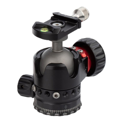
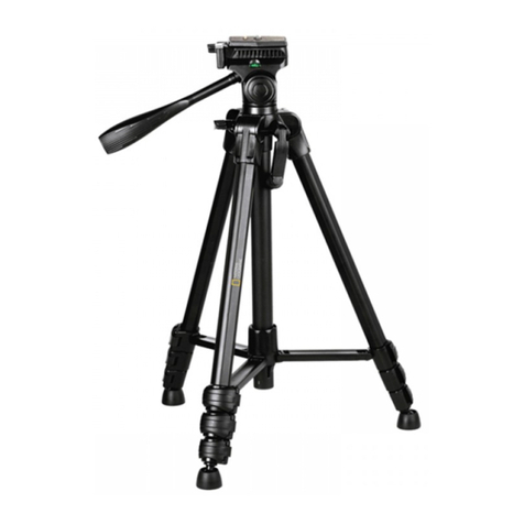
ProMediaGear BP2 User manual
Other ProMediaGear Camera Accessories manuals
ProMediaGear
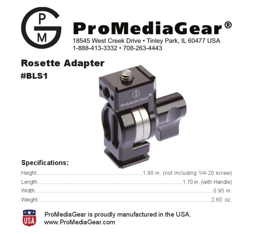
ProMediaGear Rosette Adapter BLS1 User manual
ProMediaGear
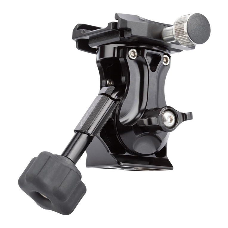
ProMediaGear HM1 User manual
ProMediaGear
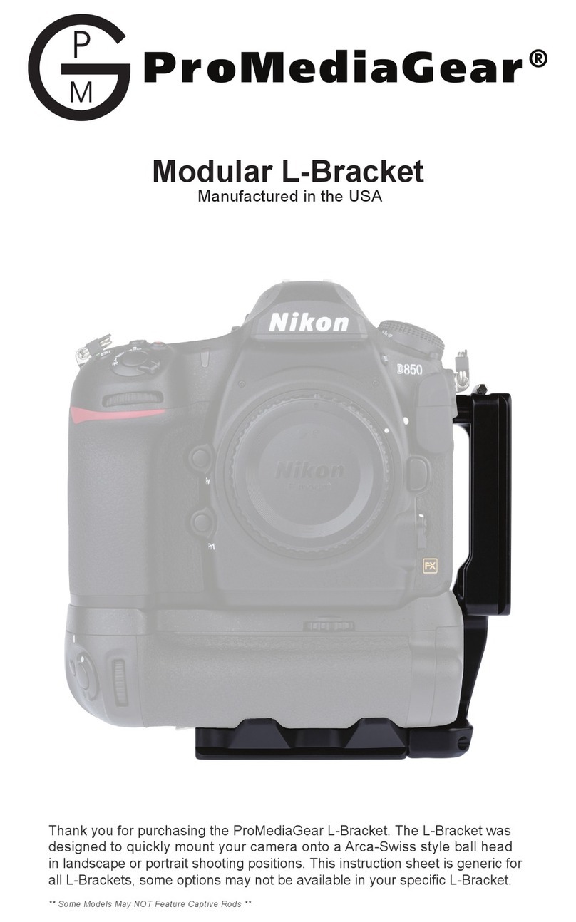
ProMediaGear Modular L-Bracket User manual
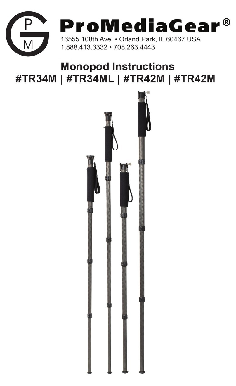
ProMediaGear
ProMediaGear TR34M User manual

ProMediaGear
ProMediaGear Katana GK User manual
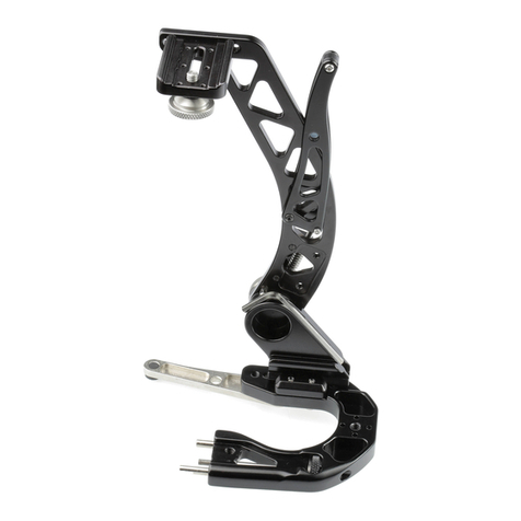
ProMediaGear
ProMediaGear Boomerang BBGv2 User manual

ProMediaGear
ProMediaGear BH1 User manual
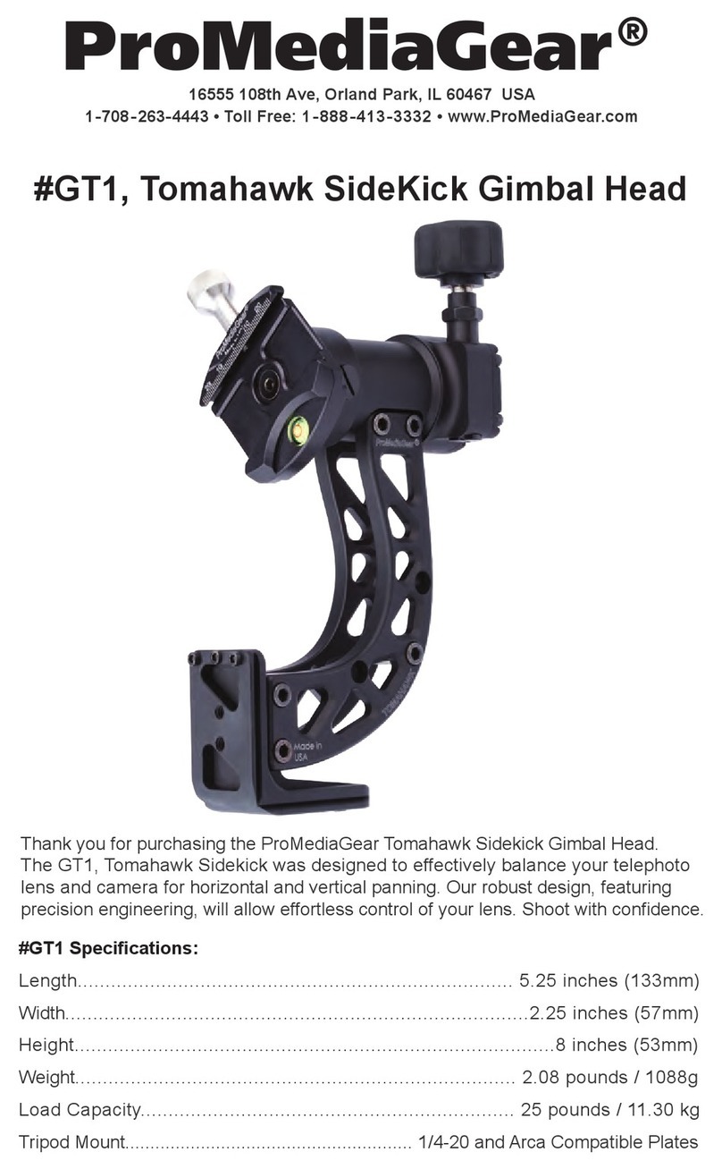
ProMediaGear
ProMediaGear GT1 User manual
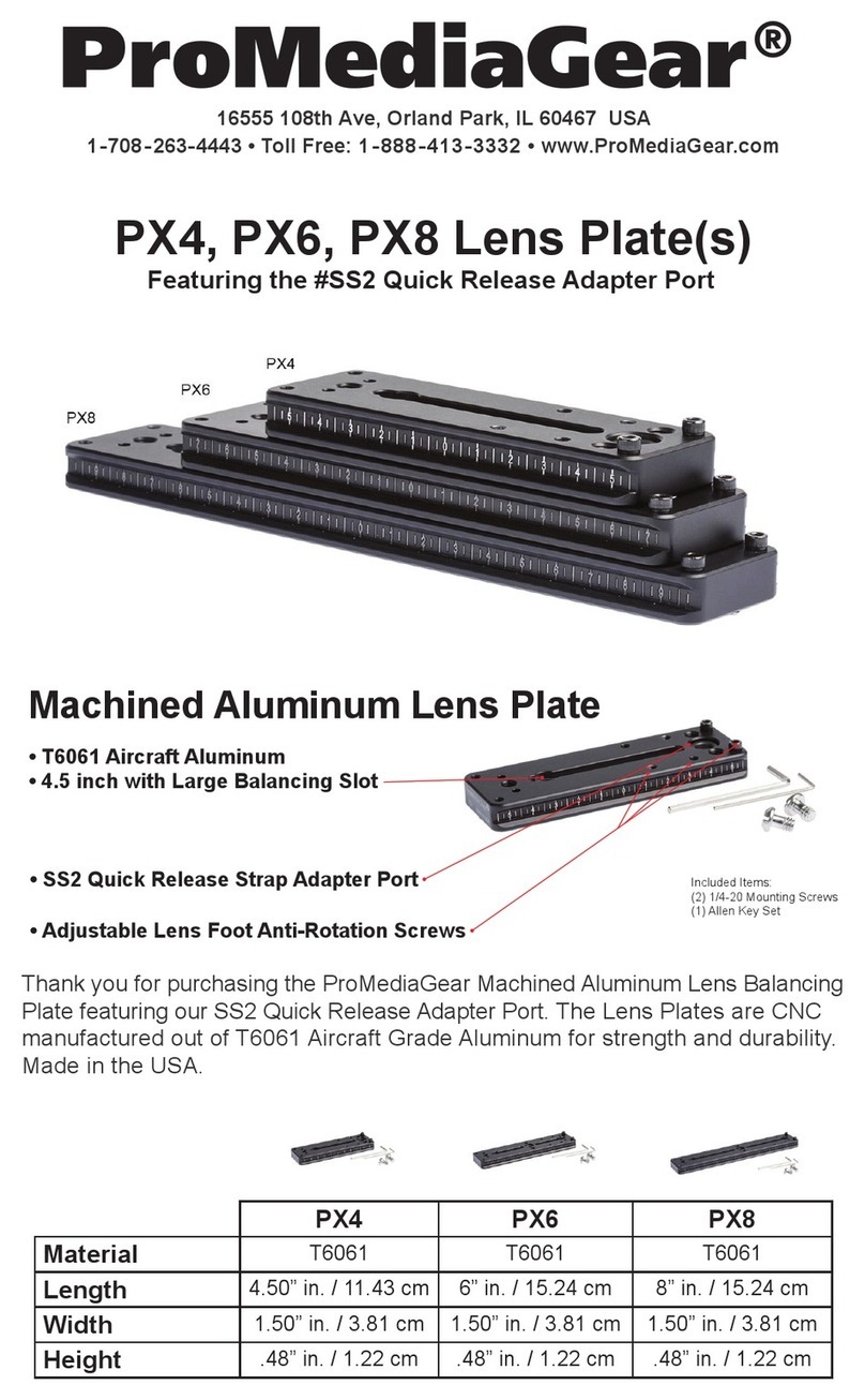
ProMediaGear
ProMediaGear PX6 User manual
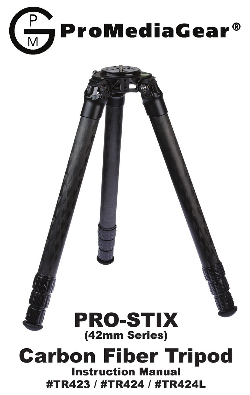
ProMediaGear
ProMediaGear Pro-Stix TR423 User manual
Popular Camera Accessories manuals by other brands
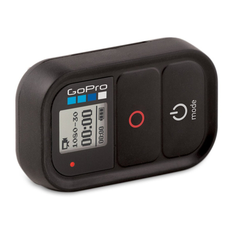
GoPro
GoPro LCD BacPac User's manual & warranty information
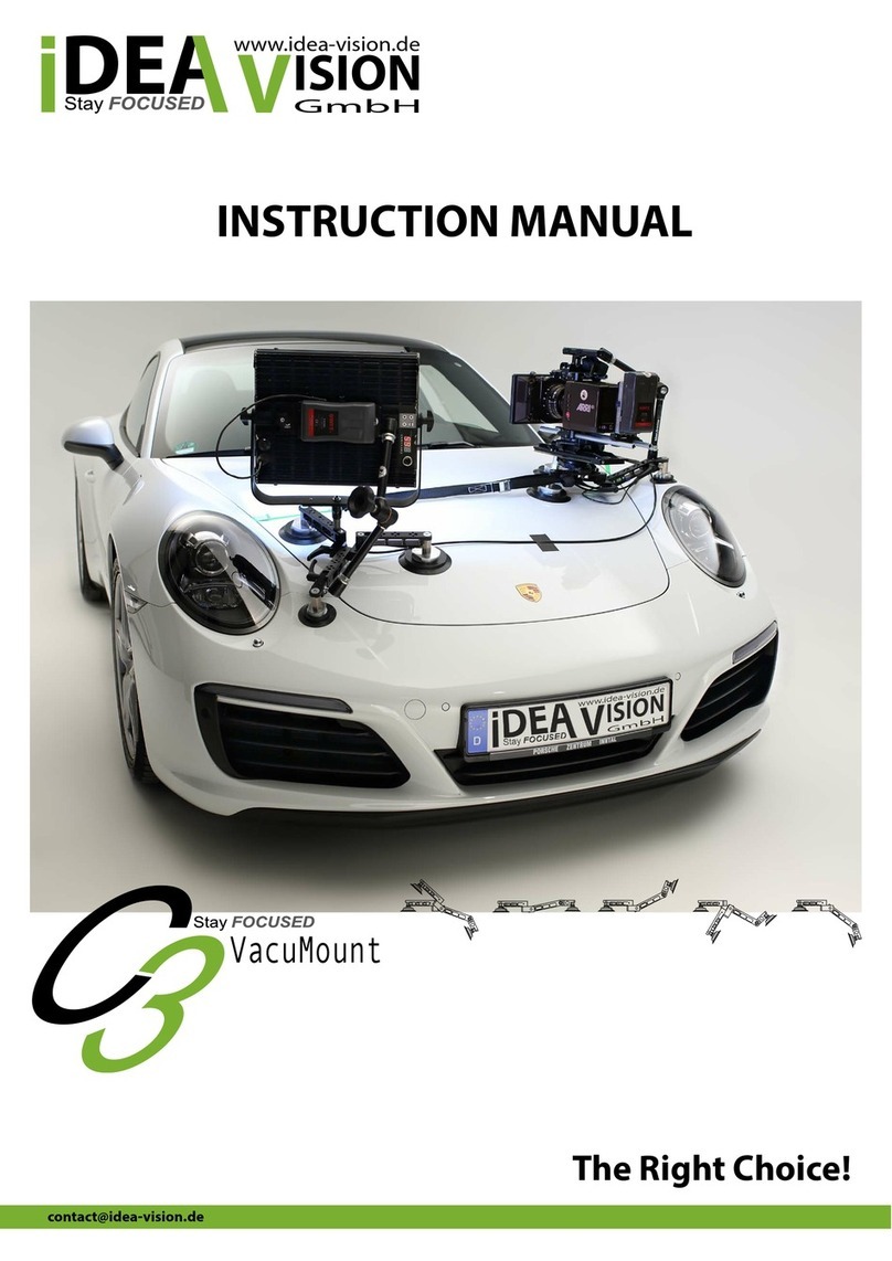
IDEA VISION
IDEA VISION C3 VacuMount instruction manual
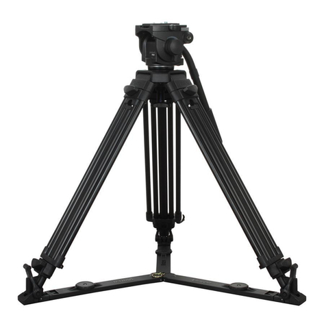
Vinten
Vinten Protouch PRO-6 HDV Operator's guide

INDELAC CONTROLS
INDELAC CONTROLS NEMA 4 ASSEMBLY, INSTALLATION, OPERATION & MAINTENANCE MANUAL
Light & Motion
Light & Motion 5060 - CAMEDIA Wide Zoom Digital Camera owner's manual
Fantasea Line
Fantasea Line UMG-02 instruction manual


