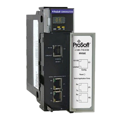
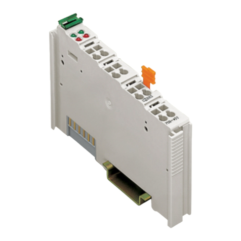
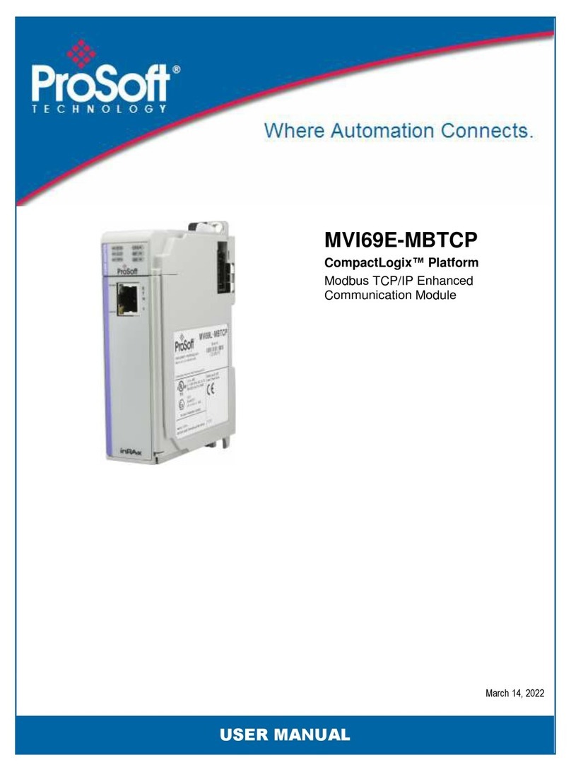
ProSoft MVI56E-61850C User manual

MVI56E-61850C
IEC 61850 Client Communication
Module
ControlLogix® Platform
September 29, 2021
USER MANUAL

ProSoft Technology, Inc. Page 2 of 116
Your Feedback Please
We always want you to feel that you made the right decision to use our products. If you have suggestions,
comments, compliments or complaints about our products, documentation, or support, please write or call
us.
How to Contact Us
ProSoft Technology, Inc.
+1 (661) 716-5100
+1 (661) 716-5101 (Fax)
www.prosoft-technology.com
support@prosoft-technology.com
MVI56E-61850C User Manual
September 29, 2021
ProSoft Technology®, is a registered copyright of ProSoft Technology, Inc. All other brand or product names
are or may be trademarks of, and are used to identify products and services of, their respective owners.
Content Disclaimer
This documentation is not intended as a substitute for and is not to be used for determining suitability or
reliability of these products for specific user applications. It is the duty of any such user or integrator to
perform the appropriate and complete risk analysis, evaluation and testing of the products with respect to
the relevant specific application or use thereof. Neither ProSoft Technology nor any of its affiliates or
subsidiaries shall be responsible or liable for misuse of the information contained herein. Information in this
document including illustrations, specifications and dimensions may contain technical inaccuracies or
typographical errors. ProSoft Technology makes no warranty or representation as to its accuracy and
assumes no liability for and reserves the right to correct such inaccuracies or errors at any time without
notice. If you have any suggestions for improvements or amendments or have found errors in this
publication, please notify us.
No part of this document may be reproduced in any form or by any means, electronic or mechanical,
including photocopying, without express written permission of ProSoft Technology. All pertinent state,
regional, and local safety regulations must be observed when installing and using this product. For reasons
of safety and to help ensure compliance with documented system data, only the manufacturer should
perform repairs to components. When devices are used for applications with technical safety requirements,
the relevant instructions must be followed. Failure to use ProSoft Technology software or approved software
with our hardware products may result in injury, harm, or improper operating results. Failure to observe this
information can result in injury or equipment damage.
Copyright © 2021 ProSoft Technology, Inc. All Rights Reserved.
For professional users in the European Union
If you wish to discard electrical and electronic equipment (EEE), please contact your dealer or
supplier for further information.
Prop 65 Warning – Cancer and Reproductive Harm – www.P65Warnings.ca.gov

ProSoft Technology, Inc. Page 3 of 116
Open Source Information
Open Source Software used in the product
The product contains, among other things, Open Source Software files, as defined below, developed by third
parties and licensed under an Open Source Software license. These Open Source Software files are
protected by copyright. Your right to use the Open Source Software is governed by the relevant applicable
Open Source Software license conditions. Your compliance with those license conditions will entitle you to
use the Open Source Software as foreseen in the relevant license. In the event of conflicts between other
ProSoft Technology, Inc. license conditions applicable to the product and the Open Source Software license
conditions, the Open Source Software conditions shall prevail. The Open Source Software is provided
royalty-free (i.e. no fees are charged for exercising the licensed rights). Open Source Software contained in
this product and the respective Open Source Software licenses are stated in the module webpage, in the
link Open Source.
If Open Source Software contained in this product is licensed under GNU General Public License (GPL),
GNU Lesser General Public License (LGPL), Mozilla Public License (MPL) or any other Open Source
Software license, which requires that source code is to be made available and such source code is not
already delivered together with the product, you can order the corresponding source code of the Open
Source Software from ProSoft Technology, Inc. - against payment of the shipping and handling charges - for
a period of at least 3 years since purchase of the product. Please send your specific request, within 3 years
of the purchase date of this product, together with the name and serial number of the product found on the
product label to:
ProSoft Technology, Inc.
Director of Engineering
9201 Camino Media, Suite 200
Bakersfield, CA 93311
USA
Warranty regarding further use of the Open Source Software
ProSoft Technology, Inc. provides no warranty for the Open Source Software contained in this product, if
such Open Source Software is used in any manner other than intended by ProSoft Technology, Inc. The
licenses listed below define the warranty, if any, from the authors or licensors of the Open Source Software.
ProSoft Technology, Inc. specifically disclaims any warranty for defects caused by altering any Open Source
Software or the product’s configuration. Any warranty claims against ProSoft Technology, Inc. in the event
that the Open Source Software contained in this product infringes the intellectual property rights of a third
party are excluded. The following disclaimer applies to the GPL and LGPL components in relation to the
rights holders:
“This program is distributed in the hope that it will be useful, but WITHOUT ANY WARRANTY; without even
the implied warranty of MERCHANTABILITY or FITNESS FOR A PARTICULAR PURPOSE. See the GNU
General Public License and the GNU Lesser General Public License for more details.”
For the remaining open source components, the liability exclusions of the rights holders in the respective
license texts apply. Technical support, if any, will only be provided for unmodified software.

MVI56E-61850C ♦IEC 61850 Client Communication Module Contents
ControlLogix® Platform User Manual
ProSoft Technology, Inc. Page 4 of 116
Contents
Your Feedback Please ....................................................................................................................... 2
How to Contact Us.............................................................................................................................. 2
Content Disclaimer ............................................................................................................................. 2
Open Source Information ................................................................................................................... 3
1Start Here 6
1.1 Overview................................................................................................................... 6
1.2 System Requirements .............................................................................................. 7
1.3 Installing the Module in the Rack.............................................................................. 7
1.4 Installing the Software .............................................................................................. 8
2Module Overview 10
2.1 Overview................................................................................................................. 10
2.2 Ethernet Ports......................................................................................................... 11
2.3 IEC 61850 Specifications........................................................................................ 11
2.4 Backplane Specifications........................................................................................ 11
2.5 Time Synchronization Specifications...................................................................... 12
2.6 LEDs ....................................................................................................................... 12
3Configuring the MVI56E-61850C Add-On Profile 13
3.1 Adding the Module to Studio 5000 Logix Designer®............................................... 13
3.1.1 Open the Studio 5000 Logix Designer Project ....................................................... 13
3.1.2 Add the MVI56E-61850C to the Studio 5000 Project ............................................. 14
3.2 Configure the IP Address........................................................................................ 17
3.3 Configure Parallel Redundancy Protocol (PRP)..................................................... 18
3.4 Enable Time Synchronization (Ethernet)................................................................ 19
3.5 Firmware Lock ........................................................................................................ 20
3.6 Disabling Backplane Communication ..................................................................... 21
3.7 Generating a Major Fault on the Controller ............................................................ 22
4Configuring the MVI56E-61850C Module 23
4.1 Configuration in the ProSoft MVI56E-61850C Configuration Manager.................. 23
4.1.1 Launch the ProSoft MVI56E-61850C Configuration Manager ............................... 23
4.1.2 Overview of the ProSoft MVI56E-61850C Configuration Manager Interface ......... 25
4.1.3 Import IED Configuration Files................................................................................ 26
4.1.4 Configure the IED Network ..................................................................................... 28
4.1.5 IED Data Mapping .................................................................................................. 30
4.1.6 Deleting one or more IEC 61850 mappings ........................................................... 35
4.1.7 Set the MMS Scan Delay and MMS Ping for an IED.............................................. 36
4.1.8 Module Properties in Configuration Manager......................................................... 38
4.1.9 Configure GOOSE Publish ..................................................................................... 43
4.1.10 Export the Configuration to the Add-On Profile ...................................................... 53
4.1.11 Files Generated by the MVI56E-61850C Configuration Manager.......................... 56
4.2 Configuration in Studio 5000 Logix Designer ......................................................... 59
4.2.1 Data Mapping Over the Backplane Connections.................................................... 59
4.2.2 Accessing GOOSE and Control Data..................................................................... 61
4.2.3 Import the MVI56E-61850C Program into Studio 5000 Logix Designer................. 62

MVI56E-61850C ♦IEC 61850 Client Communication Module Contents
ControlLogix® Platform User Manual
ProSoft Technology, Inc. Page 5 of 116
4.2.4 Updating and Reimporting a Project....................................................................... 64
4.2.5 Class 3 Explicit Messages ...................................................................................... 68
5Automatic Device Replacement (ADR) 73
6Parallel Redundancy Protocol (PRP) 74
7Time Synchronization 76
7.1 Overview................................................................................................................. 76
7.2 Diagnostics ............................................................................................................. 78
8Diagnostics and Troubleshooting 79
8.1 LED Diagnostics ..................................................................................................... 79
8.1.1 Operating Status LEDs ........................................................................................... 79
8.1.2 Ethernet LEDs......................................................................................................... 80
8.1.3 Scrolling LED .......................................................................................................... 80
8.2 ProSoft MVI56E-61850C Diagnostics Tool ............................................................ 81
8.2.1 Diagnostics Tool Overview ..................................................................................... 81
8.2.2 Diagnostics Tab ...................................................................................................... 83
8.2.3 Data Monitor ........................................................................................................... 95
8.2.4 Event Logger........................................................................................................... 99
8.3 Diagnostics Controller Tags.................................................................................. 100
8.3.1 MVI56E61850C_Diagnostics................................................................................ 100
8.3.2 Diagnostics Data Reference................................................................................. 101
8.4 Diagnostics in the MVI56E-61850C Add-On Profile............................................. 105
8.4.1 Module Info ........................................................................................................... 105
8.4.2 IED Status............................................................................................................. 106
8.4.3 PRP Diagnostics ................................................................................................... 106
8.4.4 Time Synchronization Diagnostics........................................................................ 107
8.5 Project Signature .................................................................................................. 108
8.6 CIP Diagnostics Tags ........................................................................................... 110
8.6.1 Identity .................................................................................................................. 110
8.6.2 Module .................................................................................................................. 110
8.6.3 PRP....................................................................................................................... 110
8.6.4 Backplane ............................................................................................................. 111
8.6.5 IEC61850C, General ............................................................................................ 111
8.6.6 IEC61850C, IED Status ........................................................................................ 112
9Reference 114
9.1 Specifications........................................................................................................ 114
9.1.1 IEC 61850 Client................................................................................................... 114
9.1.2 Hardware Specifications ....................................................................................... 114
10 Support, Service & Warranty 116
10.1 Contacting Technical Support............................................................................... 116
10.2 Warranty Information ............................................................................................ 116

MVI56E-61850C ♦IEC 61850 Client Communication Module Start Here
ControlLogix® Platform User Manual
ProSoft Technology, Inc. Page 6 of 116
1 Start Here
1.1 Overview
This user manual explains the features of the MVI56E-61850C module and guides you
through the installation and configuration of the module. This includes using the ProSoft
MVI56E-61850C Configuration Manager software to map data for Intelligent Electronic
Devices (IEDs) on the IEC 61850 network for use with a Rockwell Automation®
ControlLogix®processor. The configuration software creates files to import into Studio
5000 Logix Designer programming software, simplifying the integration of the module
into your system.
The high-level steps for the process of configuring the IEC 61850 network are as follows:
1 Add the MVI56E-61850C to your Studio 5000 Logix Designer project. See “Adding
the Module to Studio 5000 Logix Designer®”on page 13.
2 Configure the module Ethernet settings through the Add-On Profile. See “Configuring
the MVI56E-61850C Add-On Profile” on page 13.
3 Launch the ProSoft MVI56E-61850C Configuration Manager and take the following
steps to configure client functionality:
a Import the IED configuration files (CID or SCD files). See “Import IED
Configuration Files” on page 26.
b Add the IEDs to the IEC 61850 network. See “Configure the IED Network” on
page 28.
c Map the desired data attributes for each IED. See “Map Data Attributes for the
IEDs” on page 30.
4 Configure GOOSE Publish (server) functionality (if applicable). See “Configure
GOOSE Publish” on page 43.
5 Export the configuration to the MVI56E-61850C Add-On Profile. See “Export the
Configuration to the Add-On Profile” on page 53.
6 Import the MVI56E-61850C Program into Studio 5000 Logix Designer. See “Import
the MVI56E-61850C Program into Studio 5000 Logix Designer” on page 56.

MVI56E-61850C ♦IEC 61850 Client Communication Module Start Here
ControlLogix® Platform User Manual
ProSoft Technology, Inc. Page 7 of 116
1.2 System Requirements
The MVI56E-61850C module requires the following minimum hardware and software
components:
•Rockwell Automation Studio 5000 Logix Designer programming software version
32 or higher
•Rockwell Automation ControlLogix 5580 controller (catalog numbers starting with
1756-L8X) running firmware with the same major revision as Logix Designer, with
compatible power supply and one free slot in the rack, for the MVI56E-61850C
module. The module requires 1.4 A of backplane current (@5.1VDC).
•For remote rack applications, the MVI56E-61850C module at the remote rack
must be connected to the ControlLogix processor at the local rack through a
1756-EN4TR module.
•MVI56E-61850C Add-On Profile (AOP)
•ProSoft MVI56E-61850C Configuration Manager configuration software
•Supported operating systems:
•Microsoft Windows 10
1.3 Installing the Module in the Rack
If you have not already installed and configured your ControlLogix processor and power
supply, please do so before installing the MVI56E-61850C module. Refer to your
Rockwell Automation product documentation for installation instructions.
Warning: You must follow all safety instructions when installing this or any other electronic devices. Failure
to follow safety procedures could result in damage to hardware or data, or even serious injury or death to
personnel. Refer to the documentation for each device you plan to connect to verify that suitable safety
procedures are in place before installing or servicing the device.
Insert the MVI56E-61850C into the ControlLogix chassis using the same technique
recommended by Rockwell Automation to remove and install the Rockwell Automation
modules.
Note: You can install up to four MVI56E-61850C modules in the same ControlLogix rack.
Note: If you are using the module in a ControlLogix Redundancy System, the module must be located in a
remote rack. For more information, see “Using the Module with a ControlLogix Redundancy System” on
page 74.
You can install or remove ControlLogix system components while chassis power is
applied and the system is operating. However, please note the following warning.

MVI56E-61850C ♦IEC 61850 Client Communication Module Start Here
ControlLogix® Platform User Manual
ProSoft Technology, Inc. Page 8 of 116
Warning: When you insert or remove the module while backplane power is on, an electrical arc can occur.
An electrical arc can cause personal injury or property damage by sending an erroneous signal to your
system’s actuators. This can cause unintended machine motion or loss of process control. Electrical arcs
may also cause an explosion when they happen in a hazardous environment. Verify that power is removed
or the area is non-hazardous before proceeding.
Repeated electrical arcing causes excessive wear to contacts on both the module and
its mating connector. Worn contacts may create electrical resistance that can affect
module operation.
1 Align the module with the top and bottom guides, and then slide it into the rack until
the module is firmly against the backplane connector.
2 With a firm, steady push, snap the module into place.
3 Check that the holding clips on the top and bottom of the module are securely in the
locking holes of the rack.
4 Make a note of the slot location. You must identify the slot in which the module is
installed in order for the sample program to work correctly. Slot numbers are
identified on the green circuit board (backplane) of the ControlLogix rack.
5 Turn power ON.
Note: If you insert the module improperly, the system may stop working or may behave unpredictably.
1.4 Installing the Software
Install the MVI56E-61850C required software, which is available in the Downloads
section of the MVI56E-61850C product page on the ProSoft Technology website
(https://www.prosoft-technology.com):
•MVI56E-61850C Add-On Profile (AOP): This program includes the IEC 61850
communication module profile and associated files.

MVI56E-61850C ♦IEC 61850 Client Communication Module Start Here
ControlLogix® Platform User Manual
ProSoft Technology, Inc. Page 9 of 116
•ProSoft MVI56E-61850C Configuration Manager: This program is used to
configure all aspects associated with data communication between the MVI56E-
61850C module and remote Intelligent Electronic Devices (IEDs) according to the
IEC 61850 communication protocol.
•ProSoft MVI56E-61850C Diagnostics Tool: This application allows you to monitor
diagnostics and configuration data for the module.
Note: The same install will set up both Configuration Manager and Diagnostics Tool.

MVI56E-61850C ♦IEC 61850 Client Communication Module Module Overview
ControlLogix® Platform User Manual
ProSoft Technology, Inc. Page 10 of 116
2 Module Overview
2.1 Overview
The ProSoft Technology®IEC 61850 communication module allows Rockwell
Automation® ControlLogix®PACs to interface with IEC 61850 Intelligent Electronic
Devices (IEDs) such as substation power monitors and protective relays. The module
operates as an IEC 61850 Client supporting the polling of devices using MMS
messaging and reports. Additionally, support for GOOSE messaging as both a publisher
and subscriber allows for fast data transfer between devices on an IEC 61850 network.
The dual Ethernet ports on the module provide support for Parallel Redundancy Protocol
(PRP), and the module fully supports C37.238 Ed 2017 for precision time
synchronization of field devices.

MVI56E-61850C ♦IEC 61850 Client Communication Module Module Overview
ControlLogix® Platform User Manual
ProSoft Technology, Inc. Page 11 of 116
2.2 Ethernet Ports
Port
Description
Ports
2 GbE
Ethernet Port 1 Application port
Ethernet Port 2 Redundant port (if redudancy is enabled)
2.3 IEC 61850 Specifications
Specification
Value
Supported Standard
IEC 61850 Ed 2.0
Maximum Number of IEDs 40
Supported Reports Buffered Report Control Block (BRCB)
Unbuffered Report Control Block (URCB)
Control Direct-with-Normal-Security
SBO-with-Normal-Security
Direct-with-Enhanced-Security
SBO-with-Enhanced-Security
Maximum Number of Reports per IED 10
GOOSE GOOSE Subscription
GOOSE Publish
Maximum Number of GOOSE
Subscription per IED
4
Maximum Number of GOOSE Publish 8
Maximum Number of Tags per IED 500
Maximum Number of Tags 20,000
Status Status available per node
Report and GOOSE status available
High-level status data available within Studio 5000
2.4 Backplane Specifications
Specification
Value
Maximum Number of Class 1
Connections
225
Maximum Number of Class 1 High
Priority Connections
50
High Priority Connection RPI Range [4..9,999] ms
Normal Priority Connection RPI Range [100..9,999] ms
Maximum Class 1 Connection Input
Size
500 bytes
Maximum Class 1 Connection Output
Size
496 bytes

MVI56E-61850C ♦IEC 61850 Client Communication Module Module Overview
ControlLogix® Platform User Manual
ProSoft Technology, Inc. Page 12 of 116
2.5 Time Synchronization Specifications
Specification
Value
Time Synchronization Standard
C37.238-2017
Supported Modes
Ordinary Clock, Boundary Clock
2.6 LEDs
The module provides four diagnostic LEDs. These LEDs are used to provide information
regarding link status, parallel redundancy protocol (PRP) mode, configuration error
detection, and module operation. More information about these LEDs is in Chapter 8,
“Diagnostics and Troubleshooting.”

MVI56E-61850C ♦IEC 61850 Client Communication Module Configuring the MVI56E-61850C Add-On Profile
ControlLogix® Platform User Manual
ProSoft Technology, Inc. Page 13 of 116
3 Configuring the MVI56E-61850C Add-On Profile
3.1 Adding the Module to Studio 5000 Logix Designer®
3.1.1 Open the Studio 5000 Logix Designer Project
The first step in setting up the IEC 61850 network is opening the Studio 5000 Logix
Designer project to which you will be adding the MVI56E-61850C module.
Note: The MVI56E-61850C module requires Studio 5000 Logix Designer version 32 or higher and a
ControlLogix 5580 processor, firmware with the same major revision as Logix Designer. To check the
firmware version, right-click the controller in the Controller Organizer and select PROPERTIES.

MVI56E-61850C ♦IEC 61850 Client Communication Module Configuring the MVI56E-61850C Add-On Profile
ControlLogix® Platform User Manual
ProSoft Technology, Inc. Page 14 of 116
3.1.2 Add the MVI56E-61850C to the Studio 5000 Project
1 In the I/O Configuration section of the Controller Organizer, right-click the backplane
and select NEW MODULE.
2 Select the MVI56E-61850C module type and click CREATE (or just double-click the
module type).
Tip: To locate the module in the list, clear the MODULE TYPE VENDOR FILTERS check box and then
select the PROSOFT TECHNOLOGY filter.

MVI56E-61850C ♦IEC 61850 Client Communication Module Configuring the MVI56E-61850C Add-On Profile
ControlLogix® Platform User Manual
ProSoft Technology, Inc. Page 15 of 116
Note: If you do not see the MVI56E-61850C in the list of modules, this means that the MVI56E-61850C
AOP may not have been installed properly.
The New Module dialog box displays.
3 Enter a name for the module and a description if desired.
4 Make sure the correct slot number is selected. If the module is installed in slot 1, you
can keep the default value 1. If the module is installed in a different slot, change this
value to the appropriate slot number.
5 In the New Module window, click OK.
The New Module window closes.

MVI56E-61850C ♦IEC 61850 Client Communication Module Configuring the MVI56E-61850C Add-On Profile
ControlLogix® Platform User Manual
ProSoft Technology, Inc. Page 16 of 116
6 In the Select Module Type window, click CLOSE.
The new module appears under the backplane in the Controller Organizer panel in
Logix Designer.

MVI56E-61850C ♦IEC 61850 Client Communication Module Configuring the MVI56E-61850C Add-On Profile
ControlLogix® Platform User Manual
ProSoft Technology, Inc. Page 17 of 116
3.2 Configure the IP Address
Take the following steps to configure the IP address of the MVI56E-61850C.
1 In the I/O Configuration section of the Controller Organizer, right-click the MVI56E-
61850C module and select PROPERTIES. (Or just double-click the module.)
The Module Properties dialog box displays.
2 Select ETHERNET CONFIGURATION.
3 Select one of the following options:
•MANUALLY CONFIGURE IP ADDRESS:If you select this option, you must
manually enter values for Module IP Address, Subnet Mask, and Gateway
Address.
•OBTAIN IP SETTINGS USING DHCP:IP settings are configured automatically via
Dynamic Host Configuration Protocol (DHCP).
4 Click OK.

MVI56E-61850C ♦IEC 61850 Client Communication Module Configuring the MVI56E-61850C Add-On Profile
ControlLogix® Platform User Manual
ProSoft Technology, Inc. Page 18 of 116
3.3 Configure Parallel Redundancy Protocol (PRP)
Parallel Redundancy Protocol (PRP) allows failover protection against failure of network
components. The MVI56E-61850C provides the following two PRP modes:
•Simplex: In simplex mode, only Ethernet port 1 is used for data communication.
•Redundant: In redundant mode, both Ethernet ports 1 and 2 are used for data
communication with redundancy.
When redundant mode is enabled, you can the monitor the status of LAN A (Ethernet
port 1) and LAN B (Ethernet port 2) on the PRP Network Redundancy tab of the Module
Properties dialog box, as explained in “PRP Diagnostics” on page 106.
For more information on PRP, see “Parallel Redundancy Protocol (PRP)” on page 74.

MVI56E-61850C ♦IEC 61850 Client Communication Module Configuring the MVI56E-61850C Add-On Profile
ControlLogix® Platform User Manual
ProSoft Technology, Inc. Page 19 of 116
3.4 Enable Time Synchronization (Ethernet)
The module supports time synchronization over three different ports: the backplane,
Ethernet Port 1, and Ethernet Port 2 (if redundancy is enabled). Time synchronization
over the backplane is always enabled. The following procedure explains how to enable
time synchronization over the Ethernet ports. If time synchronization over Ethernet is
disabled, the module operates as an ordinary clock. If time synchronization over
Ethernet is enabled, the module operates as boundary clock. For more information
regarding this feature, see “Time Synchronization” on page 76.
1 In the Module Properties dialog box, select ETHERNET CONFIGURATION.
2 Under Time Synchronization, select ENABLED.
3 Click OK.

MVI56E-61850C ♦IEC 61850 Client Communication Module Configuring the MVI56E-61850C Add-On Profile
ControlLogix® Platform User Manual
ProSoft Technology, Inc. Page 20 of 116
3.5 Firmware Lock
The module firmware is locked by default for security purposes to prevent the firmware
upgrade. In case a firmware upgrade is required, you will have to unlock the firmware
through the Firmware Lock parameter.
For more information about firmware upgrades, see the Downloads section of the
MVI56E-61850C product page on the ProSoft Technology website (https://www.prosoft-
technology.com).
1 In the Module Properties dialog box, select ETHERNET CONFIGURATION.
2 Under Firmware Lock, select UNLOCKED.
3 Click OK.
4 Before upgrading the firmware, set the ControlLogix processor to PROGRAM mode.
5 Once you are finished with the Ethernet configuration, you are ready to launch the
ProSoft MVI56E-61850C Configuration Manager software. Refer to the following
section for details.
Table of contents
Other ProSoft Control Unit manuals

ProSoft
ProSoft MVI56E-MCMR User manual

ProSoft
ProSoft ProLinx 6104-WA-PDPM User manual

ProSoft
ProSoft inRAx MVI56-DEM User manual

ProSoft
ProSoft MVI56E-MCMR User manual

ProSoft
ProSoft PTQ-LNG User manual

ProSoft
ProSoft MVI ADMNET Series Instruction Manual

ProSoft
ProSoft MVI69E-MBS User manual

ProSoft
ProSoft MVI56-HART User manual

ProSoft
ProSoft inRAx MVI46-BSAPS User manual

ProSoft
ProSoft PLX51-DF1-MSG User manual