ProSoft ProLinx 6104-WA-PDPM User manual

6104-WA-PDPM 6105-WA-PDPS
ProLinx Wireless PROFIBUS Modules
PROFIBUS Master and Slave
Setup Guide
June 02, 2006

Please Read This Notice
Successful application of this module requires a reasonable working knowledge of the ProLinx
Module, its connected devices, and the application in which the combination is to be used. For this
reason, it is important that those responsible for implementation satisfy themselves that the
combination will meet the needs of the application without exposing personnel or equipment to
unsafe or inappropriate working conditions.
This manual is provided to assist the user. Every attempt has been made to assure that the
information provided is accurate and a true reflection of the product's installation requirements. In
order to assure a complete understanding of the operation of the product, the user should read all
applicable documentation on the operation of the connected devices.
Under no conditions will ProSoft Technology, Inc. be responsible or liable for indirect or
consequential damages resulting from the use or application of the product.
Reproduction of the contents of this manual, in whole or in part, without written permission from
ProSoft Technology, Inc. is prohibited.
Information in this manual is subject to change without notice and does not represent a
commitment on the part of ProSoft Technology, Inc. Improvements and/or changes in this manual
or the product may be made at any time. These changes will be made periodically to correct
technical inaccuracies or typographical errors.
Your Feedback Please
We always want you to feel that you made the right decision to use our products. If you have
suggestions, comments, compliments or complaints about the product, documentation or support,
please write or call us.
ProSoft Technology, Inc.
1675 Chester Avenue, Fourth Floor
Bakersfield, CA 93301
(661) 716-5100
(661) 716-5101 (Fax)
http://www.prosoft-technology.com
Copyright © ProSoft Technology, Inc. 2000 - 2006. All Rights Reserved.
6104-WA-PDPM 6105-WA-PDPS Setup Guide
June 02, 2006
Important Installation Instructions
Power, input and output wiring must be in accordance with Class I, Division 2
wiring methods - Article 501-4 (b) of the National Electrical Code, NFPA 70 and
in accordance with the authority having jurisdiction. The following warnings must
be heeded:
a WARNING - EXPLOSION HAZARD - SUBSTITUTION OF COMPONENTS
MAY IMPAIR SUITABILITY FOR CLASS I, DIV. 2;

b WARNING - EXPLOSION HAZARD - WHEN IN HAZARDOUS LOCATIONS,
TURN OFF POWER BEFORE REPLACING OR WIRING MODULES, and
c WARNING - EXPLOSION HAZARD - DO NOT DISCONNECT EQUIPMENT
UNLESS POWER HAS BEEN SWITCHED OFF OR THE AREA IS KNOWN TO
BE NONHAZARDOUS.
d "THIS DEVICE SHALL BE POWERED BY CLASS 2 OUTPUTS ONLY."
The following Information and warnings pertaining to the radio module must be
heeded:
a "THIS DEVICE CONTAINS A TRANSMITTER MODULE, FCC ID: SDZ-
WA-1. PLEASE SEE FCC ID LABEL ON BACK OF DEVICE."
b "THIS DEVICE USES AN INTERNAL COMPACT FLASH RADIO MODULE
AS THE PRIMARY RADIO COMPONENT. THE COMPACT FLASH RADIO
MODULE DOES NOT HAVE AN FCC ID LABEL. THE COMPACT FLASH
RADIO MODULE HAS NO USER SERVICABLE PARTS."
c "THIS DEVICE COMPLIES WITH PART 15 OF THE FCC RULES.
OPERATION IS SUBJECT TO THE FOLLOWING TWO CONDITIONS: (1) THIS
DEVICE MAY NOT CAUSE HARMFUL INTERFERENCE, AND (2) THIS
DEVICE MUST ACCEPT ANY INTERFERENCE RECEIVED, INCLUDING
INTERFERENCE THAT MAY CAUSE UNDESIRED OPERATION."
d "THIS DEVICE AND ANY RADIO ACCESSORY SOLD BY PROSOFT MUST
BE INSTALLED BY AN AUTHORIZED PROFESSIONAL INDUSTRIAL RADIO
SYSTEM INTEGRATOR. FURTHER, ONLY RADIO ACCESSORIES SOLD BY
PROSOFT AND SPECIFICALLY TESTED FOR USE WITH THIS DEVICE MAY
BE USED WITH THIS DEVICE."
e "THE USER OF THIS EQUIPMENT CANNOT BE WITHIN 20 cm. FROM
THE RADIATING ELEMENT DEVICE."
f "CHANGES OR MODIFICATIONS NOT EXPRESSLY APPROVED BY THE
PARTY RESOPNSIBLE FOR COMPLIANCE COULD VOID THE USER'S
AUTHORITY TO OPERATE THE EQUIPMENT."
Industry Canada Requirements:
a "THIS DEVICE HAS BEEN DESIGNED TO OPERATE WITH AN
ANTENNA HAVING A MAXIMUM GAIN OF 24 dB. AN ANTENNA
HAVING A HIGHER GAIN IS STRICTLY PROHIBITED PER
REGULATIONS OF INDUSTRY CANADA. THE REQUIRED ANTENNA
IMPEDANCE IS 50 OHMS."
b "TO REDUCE POTENTIAL RADIO INTERFERENCE TO OTHER USERS,
THE ANTENNA TYPE AND ITS GAIN SHOULD BE CHOSEN SUCH THAT THE
EQUIVALENT ISOTROPICALLY RADIATED POWER (EIRP) IS NOT MORE
THAN THAT REQUIRED FOR SUCCESSFUL COMMUNICATION."
c "THE INSTALLER OF THIS RADIO EQUIPMENT MUST INSURE THAT THE
ANTENNA IS LOCATED OR POINTED SUCH THAT IT DOES NOT EMIT RF
FIELD IN EXCESS OF HEALTH CANADA LIMITS FOR THE GENERAL

POPULATION; CONSULT SAFETY CODE 6, OBTAINABLE FROM HEALTH
CANADA."
WARNING:
This is a Class A product. In a domestic environment this product may cause
radio interference in which case the user may be required to take adequate
measures.

Contents 6104-WA-PDPM 6105-WA-PDPS ♦ProLinx Wireless PROFIBUS Modules
PROFIBUS Master and Slave
ProSoft Technology, Inc. Page 5 of 31
June 2, 2006
Contents
PLEASE READ THIS NOTICE...........................................................................................................2
Your Feedback Please ..................................................................................................................2
Important Installation Instructions..............................................................................................2
1INTRODUCTION .........................................................................................................................7
1.1 Before You Begin ..........................................................................................................7
1.2 Sample Network.............................................................................................................8
2GETTING STARTED...................................................................................................................9
2.1 Configuring the Wireless PROFIBUS Master..............................................................9
2.2 Configuring ProLinx Modules with ProSoft Configuration Builder........................12
2.2.1 Creating the Project and Adding Modules ...................................................................12
2.2.2 Creating a Wireless Network .......................................................................................17
3CONFIGURING DATA EXCHANGE.........................................................................................21
3.1 ProLinx Database Structure.......................................................................................21
3.1.1 PROFIBUS Module Data Allocation ............................................................................22
3.2 Data Mapping in SyCon ..............................................................................................22
3.3 Data Moving in ProLinx Configuration Builder ........................................................23
SUPPORT, SERVICE & WARRANTY.............................................................................................27
Module Service and Repair ........................................................................................................27
General Warranty Policy – Terms and Conditions...................................................................28
Limitation of Liability ..................................................................................................................29
RMA Procedures..........................................................................................................................29
INDEX ...............................................................................................................................................31

6104-WA-PDPM 6105-WA-PDPS ♦ProLinx Wireless PROFIBUS Modules Contents
PROFIBUS Master and Slave
Page 6 of 31 ProSoft Technology, Inc.
June 2, 2006

Introduction 6104-WA-PDPM 6105-WA-PDPS ♦ProLinx Wireless PROFIBUS Modules
PROFIBUS Master and Slave
ProSoft Technology, Inc. Page 7 of 31
June 2, 2006
1 Introduction
In This Chapter
¾Before You Begin..................................................................... 7
¾Sample Network....................................................................... 8
This manual is intended to guide you through the setup and configuration of your
ProLinx Wireless PROFIBUS Master and Slave devices.
1.1 Before You Begin
You need the following equipment and information before you begin:
Each module you want to configure for installation
IP Address for each wireless module you are configuring
Your radio network Subnet Mask
A channel number to use for the PLX Radio Network
oFCC allows channels 1–11
oETSI (Europe) allows channels 1–13
oFrance allows channels 1-9
PC or Laptop with SyCon configuration software installed
•Note: SyCon software is provided by ProSoft Technology with the
product. However, if you use a different configuration tool for your
PROFIBUS devices, that tool may work in place of SyCon for
configuring the modules.
PC or Laptop with ProSoft Configuration Builder software installed (ProSoft
Configuration Builder software provided)
Serial cable to connect module to computer for configuration
DB-9 to Mini-DIN8 conversion cable (provided)

6104-WA-PDPM 6105-WA-PDPS ♦ProLinx Wireless PROFIBUS Modules Introduction
PROFIBUS Master and Slave
Page 8 of 31 ProSoft Technology, Inc.
June 2, 2006
1.2 Sample Network
The sample configuration in this manual will build a network similar to the
following illustration. Steps for adding additional Wireless PROFIBUS Slaves and
Masters can be found after the initial setup routine is explained.
The ProLinx Wireless PROFIBUS Slave will be connected through the
PROFIBUS cable directly to your PROFIBUS master device. The ProLinx slave
device will then communicate wirelessly to a remote ProLinx Wireless
PROFIBUS Master device, which will be wired to your remote PROFIBUS slave
devices.
This model allows you to easily attach one or more remote slave devices to a
master device wirelessly without worrying about how the slow transmission rates
or timeouts in the token rotation common to wired PROFIBUS communication.
This is accomplished by using the ProSoft Wireless Protocol (PWP) to handle the
wireless transmission between our gateway devices. The gateway devices
handle the movement between PROFIBUS packets and PWP for wireless
transfer through the use of a common database. This allows the remote master
gateway to act as a data concentrator for the slave devices attached to it. It then
reports that data wirelessly to the slave, which will in turn relay it to your master
device during the rotation.

Getting Started 6104-WA-PDPM 6105-WA-PDPS ♦ProLinx Wireless PROFIBUS Modules
PROFIBUS Master and Slave
ProSoft Technology, Inc. Page 9 of 31
June 2, 2006
2 Getting Started
In This Chapter
¾Configuring the Wireless PROFIBUS Master........................... 9
¾Configuring ProLinx Modules with ProSoft Configuration Builder
............................................................................................... 11
This chapter will go through the process of setting up your ProLinx Wireless
PROFIBUS modules to communicate in your network. We will first configure a
Wireless PROFIBUS Master device to communicate with your slave devices.
Then we will configure the wireless network which will allow the two gateways to
communicate. In the next chapter we will configure the data exchange command
portion of both ProLinx modules to move your data from one to the other
wirelessly.
2.1 Configuring the Wireless PROFIBUS Master
Before running the configuration software, ensure that the power cable is firmly
attached to the PROFIBUS DP Master module, and that the LEDs on the front of
the module light up.
1 Connect the serial cable from your computer to the PROFIBUS Config port
on the module, located directly above the PROFIBUS Master port.
2 Run the SyCon configuration program.
3 From the File menu, select New to start a new project.

6104-WA-PDPM 6105-WA-PDPS ♦ProLinx Wireless PROFIBUS Modules Getting Started
PROFIBUS Master and Slave
Page 10 of 31 ProSoft Technology, Inc.
June 2, 2006
4 From the Insert menu, select Master… At this point the cursor will change to
reflect the fact that you are inserting a master module. Position the cursor as
seen in the image and click your primary mouse button once to insert the
module.
5 When the Insert Master dialog appears you will see PROFIBUS-DP Master
available in the list of available masters. Select it and click the Add >> button,
then click OK.
6 Your project now has a master device. Next, insert your remote slave devices
in the same fashion.
7 Save the project. We will come back to it in chapter 3.

Getting Started 6104-WA-PDPM 6105-WA-PDPS ♦ProLinx Wireless PROFIBUS Modules
PROFIBUS Master and Slave
ProSoft Technology, Inc. Page 11 of 31
June 2, 2006
8 Click on the Master device in the project screen to select it. From the Online
menu, select Download. The Device Assignment CIF Serial Driver dialog will
appear. Click the Connect button for the COM port your module is attached
to. For this example we are using COM 1. The COM check box on the far left
of the dialog should become active. Check this check box and click OK.
9 A dialog will appear that warns of interrupting communications, and asks if
you want to continue with the download. Click Yes.
10 A download progress dialog will appear, showing the current progress. When
this dialog finishes successfully it will disappear.
11 At this point, save your project again and close SyCon.

6104-WA-PDPM 6105-WA-PDPS ♦ProLinx Wireless PROFIBUS Modules Getting Started
PROFIBUS Master and Slave
Page 12 of 31 ProSoft Technology, Inc.
June 2, 2006
2.2 Configuring ProLinx Modules with ProSoft Configuration Builder
You are now ready to configure the ProLinx modules for wireless communication.
Run the ProSoft Configuration Builder (PCB). If this is your first time using PCB,
you will see the following screen.
2.2.1 Creating the Project and Adding Modules
If you have used and configured modules with PCB before, you may see those
projects listed in the tree as well as or instead of Default Project. For this
configuration step, we will create a new project and location and add the modules
to it.
1 Right-click on the Default Project folder in the tree. From the menu, select
Add Project. A new folder will appear named New Project. Start typing to
rename the project. It is suggested that you give it a meaningful name, such
as Wireless PROFIBUS Network.
Note: To keep things from getting confused, following illustrations will not
include the Default Project listing. If you wish to delete Default Project from
your PCB listing, right-click on the Default Project folder, and select Delete.
When the confirmation dialog appears, click Yes.

Getting Started 6104-WA-PDPM 6105-WA-PDPS ♦ProLinx Wireless PROFIBUS Modules
PROFIBUS Master and Slave
ProSoft Technology, Inc. Page 13 of 31
June 2, 2006
2 Right click on your new project folder. From the menu, select Add Location. A
new location folder will appear. Start typing to rename the location. It is
suggested that you give it a meaningful name, such as the facility name.

6104-WA-PDPM 6105-WA-PDPS ♦ProLinx Wireless PROFIBUS Modules Getting Started
PROFIBUS Master and Slave
Page 14 of 31 ProSoft Technology, Inc.
June 2, 2006
3 You are now ready to add modules. Right-click on your location folder and
Add Module. A new module will appear in your tree.
4 Right-click on the new module icon and select Choose Module Type from the
menu. The Choose Module Type dialog will open.
5 In the Product Line Filter section, select PLX6K (which stands for ProLinx
6000, the wireless gateway product line).

Getting Started 6104-WA-PDPM 6105-WA-PDPS ♦ProLinx Wireless PROFIBUS Modules
PROFIBUS Master and Slave
ProSoft Technology, Inc. Page 15 of 31
June 2, 2006
6 In Step 1 : Select Module Type, select 6204-WA-PDPM from the drop down
menu. Your screen should now look the same as the illustration below.

6104-WA-PDPM 6105-WA-PDPS ♦ProLinx Wireless PROFIBUS Modules Getting Started
PROFIBUS Master and Slave
Page 16 of 31 ProSoft Technology, Inc.
June 2, 2006
7 Click OK to add the module to your project. Your project should now look
similar to the illustration below.
8 Repeat steps 3 through 7 to add your Wireless PROFIBUS Slave module. In
step 6, be sure to select 6205-WA-PDPS instead of the master.

Getting Started 6104-WA-PDPM 6105-WA-PDPS ♦ProLinx Wireless PROFIBUS Modules
PROFIBUS Master and Slave
ProSoft Technology, Inc. Page 17 of 31
June 2, 2006
2.2.2 Creating a Wireless Network
Now that you have your project created and both modules added, it is time to
configure the module radio network that the modules will use to communicate.
1 Under the slave module, expand the PDPS element, and double-click
PROFIBUS Slave. The Edit – PROFIBUS Slave dialog opens.

6104-WA-PDPM 6105-WA-PDPS ♦ProLinx Wireless PROFIBUS Modules Getting Started
PROFIBUS Master and Slave
Page 18 of 31 ProSoft Technology, Inc.
June 2, 2006
2 Change Slave Address to an appropriate value for use on your PROFIBUS
Master network. Click OK.
3 Under the slave module, double-click Radio Ethernet Configuration. The Edit
– WATTCP dialog opens.
Certain line items are prefixed with **. This indicates an item that must be
modified from its default value, but has not yet been.

Getting Started 6104-WA-PDPM 6105-WA-PDPS ♦ProLinx Wireless PROFIBUS Modules
PROFIBUS Master and Slave
ProSoft Technology, Inc. Page 19 of 31
June 2, 2006
Note: my_ip, netmask, and gateway are not the same as their radio equivalent
parameters. This module uses only the radio specific parameters.
4 Set ** Radio_IP as specified by your radio network administrator. Note which
IP address is used for which device.
5 Unless otherwise specified by your radio network administrator, set **
Radio_Subnet_Mask to 255.255.255.255.
6 Set **Radio_Default_Gateway as specified by your radio network
administrator.
7 Set **Network_Name_(SSID) to a unique value with no spaces. This name is
used to identify the radio network (for example, WA_PDP).
8 Set Station_Name to a unique name for this module (for example,
PROFIBUS_Slave).
9 Set Channel as specified by your radio network administrator. Notes on this
value are listed in PCB, as well as in the Getting Started section of this
manual.
10 If desired, you may set the WEP Keys and enable encryption for security
purposes. For more information on that, please reference the PWP Driver
Manual.
11 Repeat steps 4–10 for the master device
At this point your devices are configured to communicate wirelessly. In the
following chapter we will discuss configuring data exchange.

6104-WA-PDPM 6105-WA-PDPS ♦ProLinx Wireless PROFIBUS Modules Getting Started
PROFIBUS Master and Slave
Page 20 of 31 ProSoft Technology, Inc.
June 2, 2006
This manual suits for next models
1
Table of contents
Other ProSoft Control Unit manuals
ProSoft
ProSoft MVI56E-MNETCR User manual
ProSoft
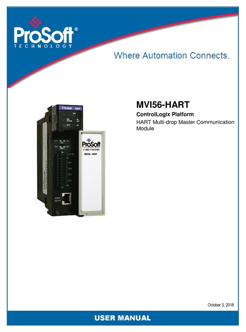
ProSoft MVI56-HART User manual

ProSoft
ProSoft MVI69E-MBS User manual
ProSoft
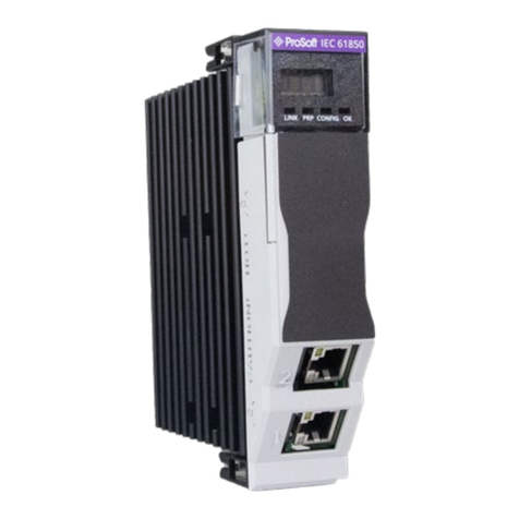
ProSoft MVI56E-61850C User manual
ProSoft
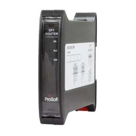
ProSoft PLX51-DF1-MSG User manual
ProSoft
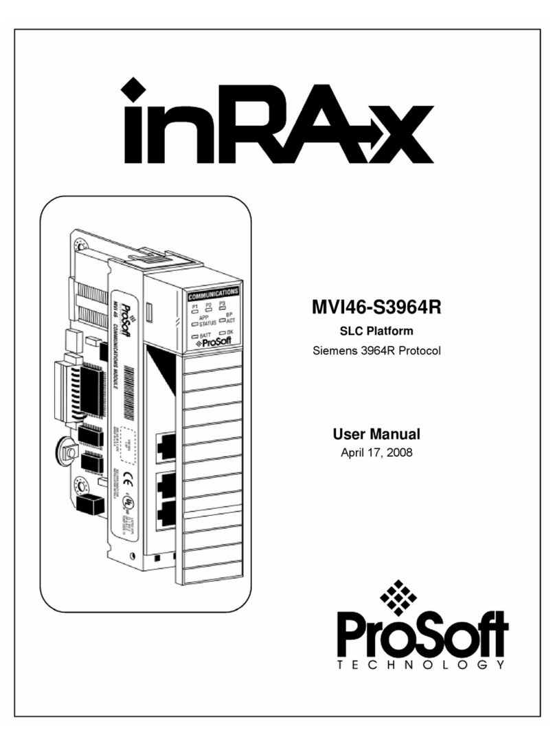
ProSoft MVI46-S3964R User manual
ProSoft
ProSoft MVI ADMNET Series Instruction Manual
ProSoft
ProSoft MVI69E-MBTCP User manual
ProSoft
ProSoft MVI56E-GEC User manual
ProSoft
ProSoft MVI56E-FLN User manual
