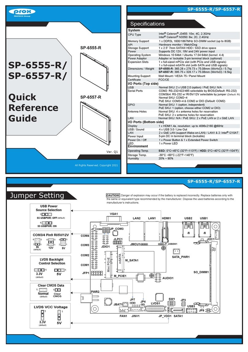
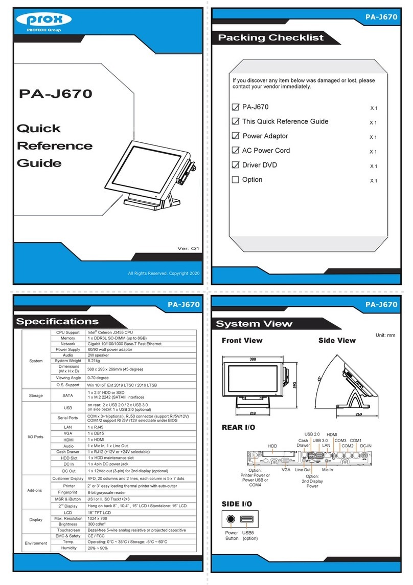
protech prox SP-C085 User manual

USER
MANUAL
SP-C085 / SP-C105 /
SP-C155 / SP-C175
8.4” / 10.4” / 15”/ 17”
VESA Mount / Wall Mount Standalone
LCD Touch Monitor
SP-C085/SP-C105/SP-C155/SP-C175 M1

SP-C085 / SP-C105 / SP-C155 / SP-C175
8.4” / 10.4” / 15” / 17”
VESA Mount / Wall Mount
Standalone LCD Touch Monitor
COPYRIGHT NOTICE & TRADEMARK
All trademarks and registered trademarks mentioned herein are the
property of their respective owners.
This manual is copyrighted in Apr. 2019. You may not reproduce or
transmit in any form or by any means, electronic, or mechanical,
including photocopying and recording.
DISCLAIMER
This user’s manual is meant to assist users in installing and setting up
the standalone LCD touch monitor. The information contained in this
document is subject to change without any notice.
CE NOTICE
This is a class A product. In a domestic environment this product may
cause radio interference in which case the user may be required to take
adequate measures.

FCC NOTICE
This equipment has been tested and found to comply with the limits for
a Class A digital device, pursuant to part 15 of the FCC Rules. These
limits are designed to provide reasonable protection against harmful
interference when the equipment is operated in a commercial
environment. This equipment generates, uses, and can radiate radio
frequency energy and, if not installed and used in accordance with the
instruction manual, may cause harmful interference to radio
communications. Operation of this equipment in a residential area is
likely to cause harmful interference in which case the user will be
required to correct the interference at his own expense.
You are cautioned that any change or modifications to the equipment
not expressly approve by the party responsible for compliance could
void your authority to operate such equipment.
WARNING: Some internal parts of the LCD Monitor may have
high electrical voltage. We strongly recommend that only
qualified engineers are allowed to service and disassemble the
LCD Monitor. If any damages should occur on the LCD monitor
and are caused by unauthorized servicing, it will not be covered
by the product warranty.
WARNING: Some internal parts of the LCD monitor may have
high electrical voltage. We strongly recommend that only
qualified engineers are allowed to service and disassemble the
LCD monitor. If any damages should occur on the LCD Monitor
and are caused by unauthorized servicing, it will not be covered
by the product warranty. Please operate the LCD and
Touchscreen with extra care as they can break easily.

i
Contents
Revision History .............................................................................................iv
1Introduction ......................................................................................... 1-1
1.1 About This Manual ..................................................................... 1-2
2Getting Started .................................................................................... 2-1
2.1 Package List............................................................................... 2-2
2.2 SP-C085 Overview..................................................................... 2-3
2.3 SP-C105 Overview..................................................................... 2-5
2.4 SP-C155 Overview..................................................................... 2-7
2.5 SP-C175 Overview..................................................................... 2-9
2.6 Technical Specifications ........................................................... 2-11
2.7 Safety Precautions ................................................................... 2-13
3Hardware Configuration ..................................................................... 3-1
3.1 External I/O Ports Diagram ........................................................ 3-2
3.1.1 Rear I/O Ports Diagram ...................................................... 3-2
3.2 JUMPER & CONNECTOR QUICK REFERENCE TABLE......... 3-3
3.3 COMPONENT LOCATIONS OF A/D BOARD............................ 3-4
3.3.1Top View of A/D Board ........................................................ 3-4
3.3.2 Bottom View of A/D Board .................................................. 3-6
3.4 HOW TO SET JUMPERS .......................................................... 3-7
3.5 Setting A/D Board Connectors and Jumpers ............................. 3-9
3.5.1 Inverter Connector (J7)....................................................... 3-9
3.5.2 OSD Keypad Connector (J6) .............................................. 3-9

ii
3.5.3 IR Connector (J11)............................................................ 3-10
3.5.4 Ext. Amp. Connector (J12)................................................3-10
3.5.5 LCD Panel Connector for LVDS (J5) ................................3-10
3.5.6 Panel 3.3V / 5V / 12V Selection (JP1) (for SP-C085, SP-C105,
SP-C155 Only).................................................................. 3-11
3.5.7 Panel 3.3V / 5V / 12V Selection (JP1) (for SP-C175 Only) .....
......................................................................................... 3-12
3.5.8 PWM / Analog Selection (JP2).......................................... 3-13
3.6 TOUCH CONTROL BOARD SR-6145 CONNECTOR QUICK
REFERENCE TABLE (For SP-C155, SP-C175 Only) .............3-14
3.7 TOUCH CONTROL BOARD SR-6145 COMPONENT
LOCATIONS (For SP-C155, SP-C175 Only) ...........................3-14
3.7.1 Touch Control Board SR-6145 Top View .......................... 3-14
3.8 Setting Touch Control Board SR-6145 Connectors and Jumpers
(For SP-C155, SP-C175 Only)................................................. 3-15
3.8.1 Control Signal Connector.................................................. 3-15
3.8.2 LVDS Panel Signal Connector (Connected To Motherboard)..
......................................................................................... 3-16
3.8.3 LVDS Panel Signal Connector (Connected To LCD Panel).....
......................................................................................... 3-17
3.8.4 15" Panel LED Backlight Control Connector .................... 3-18
3.8.5 Touch Panel Connector ....................................................3-18
3.8.6 LED1 Connector ............................................................... 3-19
3.8.7 Touch Panel Up Signal Setting ......................................... 3-20
3.8.8 Touch Panel Low Signal Setting ....................................... 3-21
3.9 OSD Key Pad Functions .......................................................... 3-22
Appendix A Exploded Diagrams.................................................A-1

iii
SP-C085 Resistive LCD Monitor Exploded Diagram ...............................A-2
SP-C085 P-CAP LCD Monitor Exploded Diagram ...................................A-3
SP-C105 Resistive LCD Monitor Exploded Diagram ...............................A-4
SP-C105 P-CAP LCD Monitor Exploded Diagram ...................................A-5
SP-C155 Resistive LCD Monitor Exploded Diagram ...............................A-6
SP-C155 P-CAP LCD Monitor Exploded Diagram ...................................A-8
SP-C175 Resistive LCD Monitor Exploded Diagram .............................A-10
SP-C175 P-CAP LCD Monitor Exploded Diagram .................................A-12
SP-C085 Touch Panel Exploded Diagram .............................................A-14
SP-C105 Touch Panel Exploded Diagram .............................................A-15
SP-C085 / SP-C105 Panel Module Assembly Exploded Diagram .........A-16
SP-C155 / SP-C175 Panel Module Assembly Exploded Diagram .........A-17
A/D Box Assembly Exploded Diagram ...................................................A-18
SP-C085/SP-C105 Wall O-Ring Installation Exploded Diagram ............A-19
SP-C155/SP-C175 Wall O-Ring Installation Exploded Diagram ............A-20
SP-C085/SP-C105 Hook Installation Exploded Diagram (1) .................A-21
SP-C085/SP-C105 Hook Installation Exploded Diagram (2) .................A-22
SP-C085/SP-C105 Hook Installation Exploded Diagram (3) .................A-23
SP-C155/SP-C175 Hook Installation Exploded Diagram (1) .................A-24
SP-C155/SP-C175 Hook Installation Exploded Diagram (2) .................A-25
SP-C155/SP-C175 Hook Installation Exploded Diagram (3) .................A-26
SP-C085/SP-C105 VESA Mount Installation Exploded Diagram...........A-27
SP-C155/SP-C175 VESA Mount Installation Exploded Diagram...........A-28

iv
Revision History
The revision history of SP-C085 / SP-C105 / SP-C155 / SP-C175 User Manual
is described below:
Version No.
Revision History
Page No.
Date
M1
Initial Release
- 2019/04/15

SP-C085/C105/C155/C175 SERIES USER MANUAL
Page: 1-1
1Introduction
This chapter provides the introduction for SP-C085 /
SP-C105 / SP-C155 / SP-C175 standalone LCD touch
monitor as well as the framework of the user manual.
The following topic is included:
•About This Manual

Chapter 1 Introduction
SP-C085/C105/C155/C175 SERIES USER MANUAL
Page: 1-2
1.1 About This Manual
Thank you for purchasing our SP-C085 / SP-C105 / SP-C155 / SP-C175 standalone
LCD touch monitor. This manual is designed to assist you how to install and set up
the whole LCD touch monitor. It contains 3 chapters and 1 appendix. Users can
configure the device according to their own needs. This user manual is intended for
service personnel with strong hardware background. It is not intended for general
users.
The following section describes the structure of this user manual.
Chapter 1 Introduction
This chapter introduces the framework of this user manual.
Chapter 2 Getting Started
This chapter describes the package contents and specifications, and illustrates the
physical appearances for SP-C085 / SP-C105 / SP-C155 / SP-C175. Read the safety
reminders carefully on how to take care of the LCD monitor properly.
Chapter 3 Hardware Configuration
This chapter describes the locations and functions of the A/D board components. You
will learn how to properly configure the connectors and jumpers on the A/D board,
and configure the LCD monitor to meet your own needs.
Appendix A Exploded Diagrams
This appendix provides the exploded diagrams and part numbers of SP-C085 /
SP-C105 / SP-C155 / SP-C175.

SP-C085/C105/C155/C175 SERIES USER MANUAL
Page: 2-1
2Getting Started
This chapter provides the information for SP-C085 /
SP-C105 / SP-C155 / SP-C175 standalone LCD
touch monitor.It describes the outlook of the LCD
monitor and outlines thetechnical specifications.
The following topics are included:
•Package List
•SP-C085 Overview
•SP-C105 Overview
•SP-C155 Overview
•SP-C175 Overview
•Technical Specifications
•Safety Precautions
Experienced users can go to Chapter 3 Hardware
Configuration on page 3-1 for a quick start.

Chapter 2 Getting Started
SP-C085/C105/C155/C175 SERIES USER MANUAL
Page: 2-2
2.1 Package List
If you discover any of the items listed below are damaged or lost, please
contact your local distributor immediately.
Item
Q’ty
SP-C085 / SP-C105 / SP-C155 / SP-C175
1
Manual / Driver DVD
1
Quick Guide
1

Chapter 2 Getting Started
SP-C085/C105/C155/C175 SERIES USER MANUAL
Page: 2-3
2.2 SP-C085 Overview
Unit: mmUnit: mm
Front View
224.8
176.8
C.L.100(VESA)
C.L.100(VESA)
15.8
215.6
184
VGA DVI HDMI DC12V USB
(Touch)
49 5.5
Top View
Rear View
Bottom View
Side View
13.9 142
165.8
18.5
25
MENU VOL- VOL+ SOURCE POWER

Chapter 2 Getting Started
SP-C085/C105/C155/C175 SERIES USER MANUAL
Page: 2-4
Quarter View

Chapter 2 Getting Started
SP-C085/C105/C155/C175 SERIES USER MANUAL
Page: 2-5
2.3 SP-C105 Overview
Unit: mmUnit: mm
C.L.100(VESA)
C.L.100(VESA)
260.1
216.5
184
249.6
32.8
VGA DVI HDMI DC12V USB
(Touch)
48.1
18 25
30
142
206
Front View Rear View
Top View Bottom View
Side View
5.1
MENU VOL- VOL+ SOURCE POWER

Chapter 2 Getting Started
SP-C085/C105/C155/C175 SERIES USER MANUAL
Page: 2-6
Quarter View

Chapter 2 Getting Started
SP-C085/C105/C155/C175 SERIES USER MANUAL
Page: 2-7
2.4 SP-C155 Overview
Unit: mmUnit: mm
279.7
365.3
C.L.100(VESA)
C.L.100(VESA)
VGA DVI HDMI DC12V USB
(Touch)
357.5
184 86.8
Front View Rear View
Top View Bottom View
Side View
53.5
23 25
62.3
142
270.5
MENU VOL- VOL+ SOURCE POWER

Chapter 2 Getting Started
SP-C085/C105/C155/C175 SERIES USER MANUAL
Page: 2-8
Quarter View

Chapter 2 Getting Started
SP-C085/C105/C155/C175 SERIES USER MANUAL
Page: 2-9
2.5 SP-C175 Overview
Unit: mmUnit: mm
Front View Rear View
C.L.100(VESA)
C.L.100(VESA)
Top View Bottom View
Side View
387.5
184 101.8
VGA DVI HDMI DC12V USB
(Touch)
5.5
MENU VOL- VOL+ SOURCE POWER
53.5
23 25
52.3142
310.5
395.8
328.2

Chapter 2 Getting Started
SP-C085/C105/C155/C175 SERIES USER MANUAL
Page: 2-10
Quarter View

Chapter 2 Getting Started
SP-C085/C105/C155/C175 SERIES USER MANUAL
Page: 2-11
2.6 Technical Specifications
LCD
Customer (2
nd Display)
SP-C085: 8.4” SVGA LCD
SP-C105: 10.4” SVGA LCD
SP-C155: 15” XGA LCD
SP-C175: 17” SXGA LCD
Display Resolution
SP-C085: LVDS 800 x 600 dots SVGA
SP-C105: LVDS 1024 x 768 dots SVGA
SP-C155: LVDS 1024 x 768 dots XGA
SP-C175: LVDS 1280 x 1024 dots SXGA
Brightness
SP-C085: Typ. 600 cd/m2
SP-C105: Typ. 450 cd/m2
SP-C155: Typ. 450 cd/m2
SP-C175: Typ. 350 cd/m2
Life time of Backlight lamp
SP-C085: Min. 30,000 hours
SP-C105: Min. 50,000 hours
SP-C155: Min. 50,000 hours
SP-C175: Min. 50,000 hours
Touch Panel
P-CAP or Resistive Touch (USB Interface) or N/A
Dimensions (Panel)
SP-C085: 225(W) x 177 (H) x 49mm(D)
SP-C105: 260 (W) x217 (H) x48mm(D)
SP-C155: 365 (W) x280 (H) x54mm(D)
SP-C175: 396 (W) x328 (H) x54mm(D)
Weight
SP-C085: 1.4kg
SP-C105: 1.8kg
SP-C155: 3.5kg
SP-C175: 4.4kg
Viewing Angle
Horizontal: -80° ~ 80°, Vertical: -80° ~ 70°
Wall Mount
VESA Mount 100 x 100 mm
Power Supply
DC 12V / 3.3A / 40W Power Adapter
(AC Input: 90 ~264 Vac, 47/63Hz)
I/O Ports
VGA
1 x VGA port
DVI-I
1 x DVI-I port (support DVI-D signals only)
HDMI
1 x HDMI port
USB
1 x USB port (touch connection)
Other manuals for prox SP-C085
1
This manual suits for next models
3
Table of contents
Other protech Touchscreen manuals
Popular Touchscreen manuals by other brands

Advantech
Advantech IDP31-215W Series user manual

Tyco
Tyco HS2TCHP E user manual

Tyco Electronics
Tyco Electronics Elo TouchSystems ET1225L-7SWC-1 user guide

Soundstream
Soundstream VRN-75HB owner's manual

Elo Touch Solutions
Elo Touch Solutions KIT-NFC-LF user manual

Elo TouchSystems
Elo TouchSystems 1515L Technische Daten